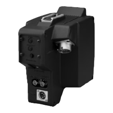
Sony BKP-7090 User manual

CAMERA UPGRADE UNIT
BKP-7090
INSTALLATION MANUAL
1st Edition (Revised 1)

!WARNING
This manual is intended for qualified service personnel only.
To reduce the risk of electric shock, fire or injury, do not perform any servicing other than that
contained in the operating instructions unless you are qualified to do so.Refer all servicing to
qualified service personnel.
!WARNUNG
Die Anleitung ist nur für qualifiziertes Fachpersonal bestimmt.
Alle Wartungsarbeiten dürfen nur von qualifiziertem Fachpersonal ausgeführt werden. Um die
Gefahr eines elektrischen Schlages, Feuergefahr und Verletzungen zu vermeiden, sind bei
Wartungsarbeiten strikt die Angaben in der Anleitung zu befolgen. Andere als die angegeben
Wartungsarbeiten dürfen nur von Personen ausgeführt werden, die eine spezielle Befähigung
dazu besitzen.
!AVERTISSEMENT
Ce manual est destiné uniquement aux personnes compétentes en charge de l’entretien. Afin
de réduire les risques de décharge électrique, d’incendie ou de blessure n’effectuer que les
réparations indiquées dans le mode d’emploi à moins d’être qualifié pour en effectuer d’autres.
Pour toute réparation faire appel à une personne compétente uniquement.

1 (E)
BKP-7090
Table of Contents
Manual Structure
Purpose of this manual ........................................................................................ 3 (E)
Relative manuals ................................................................................................. 3 (E)
1. Installation
1-1. Configuration of BKP-7090..................................................................1-1 (E)
1-2. Installing the BKP-7090 in the BVP-700/700P ....................................1-2 (E)
1-3. Electrical Alignment .............................................................................1-7 (E)
1-4. Disconnecting /Connecting Flexible Card Wire .................................1-11 (E)
1-5. Function of Internal Switches .............................................................1-12 (E)
2. Electrical Alignment
2-1. AD, DA System Adjustment.................................................................2-1 (E)
2-1-1. DA Gain Adjustment............................................................2-1 (E)
2-1-2. AD Gain Adjustment............................................................2-2 (E)
2-1-3. V Modulation Balance Adjustment......................................2-3 (E)
2-1-4. AD PHASE Adjustment.......................................................2-4 (E)
2-2. Y REF Level Adjustment......................................................................2-5 (E)
2-3. R-Y REF Level Adjustment..................................................................2-6 (E)
2-4. B-Y REF Level Adjustment..................................................................2-7 (E)


BKP-7090 3 (E)
Manual Structure
Purpose of this manual This manual is the installation manual for Camera Upgrade Unit BKP-7090.
This manual describes the information items necessary when the unit is supplied and
installed.
Relative manuals Besides this maintenance manual the following manuals are available for the unit.
..
..
.BVP-700/700P Operation Manual (Supplied with BVP-700/700P)
This manual is necessary for application and operation of this unit.
..
..
.Maintenance Manual Part 2 Volume 1, Volume 2
(Available on request)
This manual describes the information items on maintenance, and items that
premise the service based on the components parts such as alignment, schematic
diagrams, board layouts and spare parts list. When servicing the upgraded camera,
see the BKP-7090 maintenance manual and BVP-700/700P maintenance manual
together.
If this manual is required, please contact your local Sony Sales Office/Service
Center.
..
..
.BVP-700/700P Maintenance Manual Volume 1, Volume 2
(Supplied with BVP-700/700P)
This manual describes the information items on maintenance, and items that
premise the service based on the components parts such as alignment, schematic
diagrams, board layouts and spare parts list. When servicing the upgraded camera,
see the BKP-7090 maintenance manual and BVP-700/700P maintenance manual
together.
..
..
.BVP-900 Series System Manual BKP-9901 (Available on request)
This manual is necessary for connection and operation of this unit and other
peripheral equipment.
If this manual is required, please contact your local Sony Sales Office/Service
Center.


1-1 (E)
BKP-7090
The BKP-7090 is a camera upgrade unit for the BVP-700/700P. By installing the BKP-7090 in the BVP-
700/700P, the BVP-700/700P will be upgraded to a digital signal processing camera. To install proceed as
follows. When upgrading the BVP-700/700P, upgrade the incorporated OHB at the same time, or replace
it with the OHB-750A/750WSA/730/730WS (or their PAL version).
1-1. Configuration of BKP-7090
Description Q’ty Remarks
AD-148 board 1 Plug-in board
AT-120 board 1 Plug-in board
DA-128 board (with CN-1566 board) 1 Plug-in board
PR-237 board 1 Plug-in board
PS-492 board 1 Plug-in board
MB-764 board 1 Mother board
Connector panel assembly 1
Label (1) 1 Connector No. markings
Label (2) 1 Board name markings
UP GRADE label 1
Screws (PSW3 x 6) 8 Used when installing the MB-764 board
Installation Manual 1
Section 1
Installation

1-2 (E) BKP-7090
CN22
Loosen
Loosen
Rear panel
Flexible card wire
1-2. Installing the BKP-7090 in the BVP-700/700P
Tool Required
Screwdriver (Sony Part No.: 7-700-739-01or equivalent): Blade length of 200 mm or more
Replacing the mother board and plug-in boards
(1) Open the both side panels of the BVP-700/700P.
(2) Pull out all the plug-in boards while pushing the board lever in the direction of the arrow.
Loosen the two screws and pull out the power assembly while pushing the levers in the direction of
the arrow.
n
The power assembly and AU-177, MD-83 and MS-37 boards are reused later.
(3) Loosen the four screws securing the rear panel. Disconnect the flexible card wire from CN22 on the
MB-430 board.
n
Properly disconnect/connect the flexible card wire referring to Section 1-4.
Loosen
Power assembly
Lever
Lever Plug-in board
1-2. Installing the BKP-7090 in the BVP-700/700P

1-3 (E)
BKP-7090
(4) Disconnect the ten connectors and three RF cables from the MB-430 board. (It is easier to disconnect/
connect CN17 from/to the MB-430 board if removing the AC outlet panel in advance.)
n
When disconnecting the RF cable, do not pull the cable itself. Hold the connector plug portion.
(5) Remove the eight screws (PWH3 x6) securing the MB-430 board using a long-blade screwdriver.
n
When removing the screws, take care not to drop them into the camera.
1-2. Installing the BKP-7090 in the BVP-700/700P
CN31 CN21
CN32
CN23
CN12
CN13
CN24
CN25(black)
CN28(red)
CN29(blue)
CN18CN17
CN16
MB-430
*RF cable
*
*
*
MB-430
PWH3 x6
PWH3 x6
PWH3 x6
PWH3 x6

1-4 (E) BKP-7090
CN31 CN21
CN32
CN23
CN12
CN13
CN24
CN18CN17
CN16
MB-764
Label(1)
VF CN23 CCD CN24
STAND ALONE CN15(OPTION)
Partition MB-430 board
MB-764 board
Clampers
CN23 CN24(Option)
CN23 CN24 (Option)
Harness Arrangement
CN25(black)
CN28(red)
CN29(blue)
*RF cable
*
*
*
(6) Secure the MB-764 board with the supplied eight screws (PSW3 x6).
n
Tighten the screws across the connector in order of 1to 2, then tighten the remaining screws.
When tightening the screws, take care not to drop them into the camera.
(7) Place the label (1) on the partition as shown in the figure.
(8) Unclamp the harnesses and route them as shown in the figure. Connect all the connectors that were
removed in step (4).
n
Harness routing must be changed because connectors configuration for the MB-764 board differs
from that for the former MB-430 board.
MB-764
PSW3 x6
PSW3 x6
PSW3 x6
PSW3 x6
2
PSW3 x6
1
1-2. Installing the BKP-7090 in the BVP-700/700P

1-5 (E)
BKP-7090
(9) Install the power assembly that was removed in step (2).
(10) Place the label (2) on the partition as shown in the figure.
(11) Install the AU-177, MD-83 and MS-37 boards that were removed in step (2) and the five plug-in
boards supplied with the BKP-7090 in order of board name markings on the label (2).
m
.The leftmost slot that is empty is for an optional board.
.If the camera is used together with the OHB-750WSA/750WSAP/730WS/730WSP, replace the
CN-1566 board, which has been connected to the DA-128 board, with the RC-68 board.
The RC-68 board is supplied with the OHB-750WSA/750WSAP/730WS/730WSP and switches
aspect ratio.
(12) Connect the flexible card wire that was disconnected in step (3), to CN22 on the MB-764 board.
Reinstall the rear panel.
1-2. Installing the BKP-7090 in the BVP-700/700P
Plug-in board
Label(2)
DA-128
2 mm Label(2)
Partition
EN
Lever
AD PR DA MS MD AU AT PS

1-6 (E) BKP-7090
Replacing the connector panel assembly
(1) Loosen the six screws to remove the connector panel assembly. Disconnect the two connectors.
(2) Install the supplied connector panel assembly in the reverse order of removal.
n
When tightening the screw securing the lug on the right, push the lug to the direction of the BNC
connector as far as it will go and then tighten. If not, the lug is sometimes caught between the plug
and chassis when plugging in the TRACKER connector. This may cause improper connection.
Affixing the UP GRADE label
Close the both side panels. Place the UP GRADE label (supplied with the BKP-7090) as shown in the
figure.
Loosen
Loosen
Loosen
Connector panel assembly
Connector
Connector
Lug
BNC connector
TRACKER connector
1-2. Installing the BKP-7090 in the BVP-700/700P
1
UP GRADE label

1-7 (E)
BKP-7090
1-3. Electrical Alignment
Preparations
Equipment Required
CCD unit: OHB-730/730WS/750A/750WSA series, or
OHB-750/750W series +BKP-7091 (Camera upgrade board)
Camera control unit: CCU-700/700P/700A/700AP
Master setup unit: MSU-700
Extension Boards
EX-439*: Sony Part No.: A-8314-124-A
*To adjust the DA-128/PR-237 boards, prepare two of the same extension board.
Connection
Connect the above equipment referring to the BVP-700/700P maintenance manual.
1-3. Electrical Alignment

1-8 (E) BKP-7090
1
POWER R
FILTER
LOCAL
CENTER
MARKERSAFETY
ZONE UP TALY
H-POSI
WIDTH
ND
12345ABCDE
CC HEIGHT STORE
VF DETAIL PinP
CALL
CURSOR CURSOR ON button
VF DETAIL control
DISPLAY switch
RET 2 RET 1
V-POSI
GB
ON
OFF
DISPLAYMIX VF
ON ON
OFF
ON
ON
123
OFFOFF
PAGE
ON
OFF
POSITION
ON
OFF
ON
OFF
CURSOR 1/2/3 button (Use to cancel)
〈 BVP-700/700P rear panel 〉
Resetting the Control Data
(1) While holding the CURSOR ON button down, push up the DISPLAY switch from ON to PAGE.
The Maintenance menu appears on the monitor screen.
(2) Set the arrow (8) to the “Reference Store” line by turning the VF DETAIL control and press the
CURSOR ON button. The Reference Store menu appears.
(3) Set the arrow (8) to the “All Preset” line by turning the VF DETAIL control and press the
CURSOR ON button. The control data will be reset.
(4) Set the DISPLAY switch to OFF.
Setting the System Setup (NTSC only)
(1) While holding the CURSOR ON button down, push up the DISPLAY switch from ON to PAGE.
The Maintenance menu appears on the monitor screen.
(2) Set the arrow (8) to the “System Setup” line by turning the VF DETAIL control and press the
CURSOR ON button. The System Setup menu appears.
(3) Set the arrow (8) to the “Select UC/J” line by turning the VF DETAIL control and press the
CURSOR ON button to select “UC”. (Every time you push this button, it changes between UC and J.)
(4) Set the DISPLAY switch to OFF.
1-3. Electrical Alignment

1-9 (E)
BKP-7090
Adjustment
(1) Make sure that the following adjustments for the MS-37 board are completed, referring to the
BVP-700/700P maintenance manual Vol.1.
n
Read “TEST OUT connector” for “MONITOR OUT connector” in the BVP-700/700P maintenance
manual. Connect the TEST OUT connector to B-ch of a waveform monotor terminated with 75 Z.
4-3-1. MS MONITOR GAIN Adjustment
4-3-2. MS Pedestal Adjustment
4-3-3. MS Gain Adjustment
(2) Perform the following adjustments, referring to Section 2.
2-1. AD, DA Systems Adjustment
2-2. Y REF Level Adjustment
2-3. R-Y REF Level Adjustment
2-4. B-Y REF Level Adjustment
Reference File Store
After completing the above adjustments, store the reference file by using the MSU-700. For details, refer
to the system manual available separately.
n
If performing customer-necessary adjustments such as gamma, detail, knee and so on, store the reference
file after their adjustments.
(1) Press the FILE button of the menu operation block. (The FILE button will be lit.)
The File Control Menu appears on the display.
(2) Press [Reference] of the File Control Menu.
The Reference File operation menu appears.
(3) Press [Ref|Store] of the Reference File operation menu.
The Reference Store area appears.
(4) Press [Start].
When the file storage is completed, a message “Completed” appears.
(5) Press the FILE button to release the menu operation mode.
1-3. Electrical Alignment

1-10 (E) BKP-7090
B
(PAL)
B
(NTSC)
A
(NTSC)
Checking After the Adjustments
1 Setting for the TEST2 mode
(1) Press the CONFIGURATION button of the menu operation block of the MSU-700. (The CONFIGU-
RATION button will light.)
The Configuration Menu appears on the display.
(2) Press [Camera] of the Configuration Menu.
The CAM Configuration display appears.
(3) Press [10|Step] in the Test2 Mode section.
The output signal will be changed to a ten-step waveform.
(4) Press the TEST2 button on the MSU-700 control panel.
2 Checking the CAMERA TEST OUT signal
(1) Connect the waveform monitor to the TEST OUT connector on the camera.
(2) Make sure that the output signal meets the specification.
Specification: A = 100 ±1.5 IRE (NTSC)
A = 700 ±10 mV (PAL)
(3) If the specification is not met, readjust all the adjustments shown in step (2) in the above “Adjust-
ment” section.
3 Checking the CCU VBS OUT signal
(1) Connect the waveform monitor to the VBS OUT connector (one of connectors VBS 1 to VBS3) on
the CCU.
(2) Make sure that the output signal meets the specification.
Specification: B = 100 ±2 IRE (NTSC)
B = 700 ±10 mV (PAL)
(3) If the specification is not met, readjust all the adjustments shown in step (2) in the above “Adjust-
ment” section.
4 Resetting After the Completion
Return the output signal to a three-step waveform in the TEST2 mode.
(1) Press [3|Step] in the Test2 Mode section.
(2) Press the CONFIGURATION button to go off.
1-3. Electrical Alignment
A
(PAL)

1-11 (E)
BKP-7090
A
A
Conductive surface
Flexible card wire
Mother board
1-4. Disconnecting /Connecting Flexible Card Wire
The flexible card wire is used between the mother board and AT-73 board. Take care not to crimp it.
It shorten the wire life.
When disconnecting and connecting the flexible card wire, be sure to disconnect and connect the connec-
tor on the mother board.
Disconnecting
1. Turn off the power.
2. Lift up the portion A and disconnect the flexible card wire.
Connecting
[Notes|at|connection]
.Be careful not to insert the flexible card wire obliquely.
.Check that the conductive surface of the flexible card wire is not soiled with dust.
1. Insert the flexible card wire as far as it will go.
2. Push down the portions A to secure the flexible card wire.
1-4. Disconnecting /Connecting Flexible Card Wire

1-12 (E) BKP-7090
1-5. Function of Internal Switches
AT-120 board
Ref. No. Switch name Description Factory setting
S1 Factory use only Be sure to use these switches with
S2 factory-set position.
S1
S2
A B C D E F G H J K L M N PQ
1
2
3
4
5
6
7
8
9
10
11
AT-120 BOARD (A SIDE)
1-5. Function of Internal Switches

2-1 (E)
BKP-7090
CN1
TP1TP2
E1
A B C D E F GH
1
2
3
4
5
6
7
8
9
10
11
DA-128 BOARD (A SIDE)
RV4
RV3 RV1 RV2
A
2-1. AD, DA System Adjustment
Note
.Adjustment of MS-37 board and OHB must be completed.
2-1-1. DA Gain Adjustment
Preparation
.TEST 1 button/MSU-700 →ON
.WHITE CLIP OFF/MSU-700 (PAINT menu) →OFF (lit)
.MASTER GAIN/MSU-700 →+18 dB
Adjustment procedure
1. Video signal select button/BVP rear panel →R
2. Equipment: Video analyzer
Test point: TEST OUT connector/BVP side panel
Adj. point: 1RV1 (R GAIN) /DA-128 board
Specification: A = 109.5 ±0.5 IRE [NTSC]
A = 766 ±3 mV [PAL]
3. Video signal select button/BVP rear panel →G
4. Equipment: Video analyzer
Test point: TEST OUT connector/BVP side panel
Adj. point: 1RV2 (G GAIN) /DA-128 board
Specification: A = 109.5 ±0.5 IRE [NTSC]
A = 766 ±3 mV [PAL]
5. Video signal select button/BVP rear panel →B
6. Equipment: Video analyzer
Test point: TEST OUT connector/BVP side panel
Adj. point: 1RV3 (B GAIN) /DA-128 board
Specification: A = 109.5 ±0.5 IRE [NTSC]
A = 766 ±3 mV [PAL]
Section 2
Electrical Alignment

2-2 (E) BKP-7090
CN1
E1
TP701
TP300 TP703
BA C D E F GH
1
2
3
4
5
6
7
8
9
10
11
12
AD-148 BOARD (A SIDE)
TP700
TP702
TP704
TP1
TP400
TP101
TP500
TP201
RV201
RV203
RV101
RV1
RV103
RV3
A
2-1-2. AD Gain Adjustment
Note
.Before adjustment, make sure that the “2-1-1. DA Gain Adjustment” is completed.
.Reset the control data (refer to section 1-3)
Preparation
.TEST 1 button/MSU-700 →ON
.WHITE CLIP OFF/MSU-700 (PAINT menu) →OFF (lit)
.KNEE OFF button/MSU-700 →OFF (lit)
.MASTER GAIN/MSU-700 →0 dB
Adjustment procedure
1. Video signal select button/BVP rear panel →R
2. Equipment: Video analyzer
Test point: TEST OUT connector/BVP side panel
Adj. point: 1RV1 (R GAIN) /AD-148 board
Specification: A = 100.0 ±0.5 IRE [NTSC]
A = 700 ±3 mV [PAL]
3. Video signal select button/BVP rear panel →G
4. Equipment: Video analyzer
Test point: TEST OUT connector/BVP side panel
Adj. point: 1RV101 (G GAIN) /AD-148 board
Specification: A = 100.0 ±0.5 IRE [NTSC]
A = 700 ±3 mV [PAL]
5. Video signal select button/BVP rear panel →B
6. Equipment: Video analyzer
Test point: TEST OUT connector/BVP side panel
Adj. point: 1RV201 (B GAIN) /AD-148 board
Specification: A = 100.0 ±0.5 IRE [NTSC]
A = 700 ±3 mV [PAL]
2-1. AD, DA System Adjustment
Table of contents
Other Sony Camera Accessories manuals

Sony
Sony SPK-CXB Operating instructions

Sony
Sony SRK-R302 User manual

Sony
Sony VCT-670-RM User manual

Sony
Sony VF-72CPK User manual

Sony
Sony VG-C77AM User manual

Sony
Sony Alpha LA-EA4 User manual

Sony
Sony VCT-870RM User manual

Sony
Sony LA- EA5 User manual
Sony
Sony VG-C4EM User manual

Sony
Sony SH-L32WBP User manual

Sony
Sony SPK-HCE Operating instructions

Sony
Sony GPS-CS1KASP - GPS Unit For Digital Cameras User manual

Sony
Sony FDA-A1AM User manual
Sony
Sony MPK-THA User manual

Sony
Sony VCV-OH1 User manual

Sony
Sony CCU-TX50 User manual

Sony
Sony TransferJet Station TJS-1 User manual

Sony
Sony FA-SHC1AM User manual

Sony
Sony MPK-URX100A User manual

Sony
Sony VFH-990 User manual