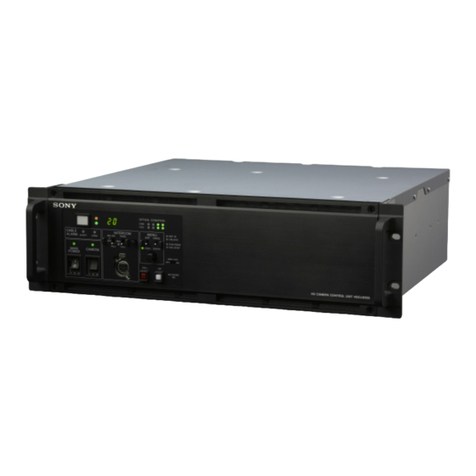
Sony CCU-700A User manual

CAMERA CONTROL UNIT
CCU-700A
MAINTENANCE MANUAL
Volume 1 2nd Edition (Revised 2)
Serial No. 15001 and Higher (UC)
Serial No. 45001 and Higher (CE)
Serial No. 50001 and Higher (UC/CE)
CCU-700AP
SDI INPUT BOARD
BKP-7312

!WARNING
This manual is intended for qualified service personnel only.
To reduce the risk of electric shock, fire or injury, do not perform any servicing other than that
contained in the operating instructions unless you are qualified to do so. Refer all servicing to
qualified service personnel.
!WARNUNG
Die Anleitung ist nur für qualifiziertes Fachpersonal bestimmt.
Alle Wartungsarbeiten dürfen nur von qualifiziertem Fachpersonal ausgeführt werden. Um die
Gefahr eines elektrischen Schlages, Feuergefahr und Verletzungen zu vermeiden, sind bei
Wartungsarbeiten strikt die Angaben in der Anleitung zu befolgen.Andere als die angegeben
Wartungsarbeiten dürfen nur von Personen ausgeführt werden, die eine spezielle Befähigung
dazu besitzen.
!AVERTISSEMENT
Ce manual est destiné uniquement aux personnes compétentes en charge de l’entretien.Afin
de réduire les risques de décharge électrique, d’incendie ou de blessure n’effectuer que les
réparations indiquées dans le mode d’emploi à moins d’être qualifié pour en effectuer d’autres.
Pour toute réparation faire appel à une personne compétente uniquement.
CAUTION
Danger of explosion if battery is incorrectly
replaced.
Replace only with the same or equivalent type
recommended by the manufacturer.
Dispose of used batteries according to the
manufacturer’s instructions.
Vorsicht!
Explosionsgefahr bei unsachgemäßem
Austausch der Batterie.
Ersatz nur durch denselben oder einen vom
Hersteller empfohlenen ähnlichen Typ.
Entsorgung gebrauchter Batterien nach Angaben
des Herstellers.
ATTENTION
Il y a danger d’explosion s’il y a remplacement
incorrect de la batterie.
Remplacer uniquement avec une batterie du
même type ou d’un type équivalent recommandé
par le constructeur.
Mettre au rebut les batteries usagées
conformément aux instructions du fabricant.
ADVARSEL!
Lithiumbatteri-Eksplosionsfare ved fejlagtig
håndtering.
Udskiftning må kun ske med batteri
af samme fabrikat og type.
Levér det brugte batteri tilbage til leverandøren.

1
CCU-700A
CCU-700AP
Table of Contents
Manual Structure
Purpose of this manual .............................................................................................. 5
Contents ..................................................................................................................... 5
Relative manuals ....................................................................................................... 5
1. Installation
1-1. Supplied Accessories ..................................................................................1-1
1-1-1. CCU-700A/700AP Supplied Accessories ..................................1-1
1-1-2. BKP-7312 Supplied Accessories ...............................................1-1
1-2. Connectors and Cables ................................................................................1-2
1-2-1. Connector Input and Output Signals ..........................................1-2
1-2-2. Cable Wiring ..............................................................................1-5
1-2-3. Connection Connector................................................................1-6
1-3. Installation...................................................................................................1-7
1-3-1. Installation Conditions ...............................................................1-7
1-3-2. Outside Dimension .....................................................................1-7
1-3-3. Installation of BKP-7312 ...........................................................1-7
1-3-4. How to Mount in 19-inch Rack..................................................1-9
1-4. Function of Internal Switch.......................................................................1-12
1-5. Coax Connector.........................................................................................1-18
1-6. Peripheral Equipments and Accessories ...................................................1-19
1-7. Instance of System Configuration .............................................................1-20
2. Service Overview
2-1. Replacement of Main Parts .........................................................................2-1
2-1-1. Removal of Front Panel .............................................................2-1
2-1-2. Removal of Rear Panel...............................................................2-1
2-1-3. Disconnecting / Connecting of Flexible Card Wire ...................2-2
2-1-4. Installation of Rear Panel ...........................................................2-2
2-1-5. Replacement of TRIAX Connector............................................2-2
2-1-6. Replacement of Power Unit .......................................................2-3
2-1-7. DC Fan Motor Replacement ......................................................2-4
2-2. Note on Servicing........................................................................................2-4
2-2-1. Precaution of Replacement Parts ...............................................2-4
2-2-2. PROM IC ...................................................................................2-4

2CCU-700A
CCU-700AP
3. Electrical Alignment
3-1. Preparation ..................................................................................................3-1
3-1-1. Equipment Required...................................................................3-1
3-1-2. Fixture ........................................................................................3-1
3-1-3. Notes on Adjustment ..................................................................3-1
3-1-4. Connection .................................................................................3-2
3-1-5. Initial Setting ..............................................................................3-3
3-2. Adjustment Items ........................................................................................3-4
3-3. Video Signal System Adjustment ...............................................................3-5
3-3-1. Sub-carrier Frequency Check.....................................................3-5
3-3-2. SC Phase Adjustment .................................................................3-5
3-3-3. SYNC Phase Adjustment ...........................................................3-6
3-3-4. BF PULSE Adjustment ..............................................................3-6
3-3-5. H Phase Adjustment ...................................................................3-7
3-3-6. CHU H Phase Adjustment .........................................................3-7
3-3-7. Color Bar Level Adjustment ......................................................3-8
3-3-8. Color Bar White Balance Adjustment........................................3-8
3-3-9. VBS 1/2/3 OUT Level Adjustment ............................................3-9
3-3-10. VBS 1/2/3 OUT Frequency Response Adjustment....................3-9
3-3-11. VBS SYNC Phase Adjustment ................................................3-10
3-3-12. I (V)/Q (U) Carrier Balance Adjustment .................................3-10
3-3-13. Color Vector Adjustment .........................................................3-11
3-3-14. Burst Adjustment .....................................................................3-11
3-3-15. CONTRAST Y Level Adjustment ...........................................3-12
3-3-16. Contrast Level Adjustment ......................................................3-12
3-3-17. MONO R-Y/B-Y Balance Adjustment ....................................3-13
3-3-18. Y BLACK Adjustment.............................................................3-13
3-3-19. Y OUT Level Adjustment ........................................................3-14
3-3-20. Y SYNC Phase Adjustment .....................................................3-14
3-3-21. R-Y/B-Y Black Balance Adjustment .......................................3-15
3-3-22. R-Y/B-Y OUT Level Adjustment ............................................3-15
3-3-23. WF 1 OUT Level Adjustment..................................................3-16
3-3-24. PIX 1 OUT Level Adjustment .................................................3-16
3-3-25. WF 2 OUT Level Adjustment..................................................3-17
3-3-26. PIX 2 OUT Level Adjustment .................................................3-17
3-3-27. G Level Adjustment .................................................................3-18
3-3-28. R Level Adjustment .................................................................3-19
3-3-29. B Level Adjustment .................................................................3-19
3-3-30. R/B DC Offset Adjustment ......................................................3-20
3-3-31. R/G/B OUT Level Adjustment ................................................3-20
3-3-32. NOTCH Adjustment PAL model only....................................3-21
3-3-33. STAIR CASE Adjustment .......................................................3-22
3-4. Y Cable Compensation System Adjustment .............................................3-23
3-4-1. SYNC SEP Adjustment............................................................3-23
3-4-2. BLACK Pulse Width Adjustment ............................................3-23
3-4-3. SYNC Sample Hold Pulse Width Adjustment .........................3-24
3-4-4. 22.5 MHz VCO DC Set Adjustment ........................................3-24

3
CCU-700A
CCU-700AP
3-4-5. Sample Pulse Width Adjustment .............................................3-25
3-4-6. Sample Pulse V Gate Width Adjustment .................................3-25
3-4-7. 22.5MHz Carrier Level Adjustment ........................................3-26
3-4-8. Y DEMOD Carrier Balance Adjustment .................................3-26
3-4-9. Y OFFSET Adjustment............................................................3-27
3-4-10. Y 1st AGC Adjustment ............................................................3-27
3-4-11. Y Output Level Adjustment .....................................................3-28
3-5. CHROMA Cable Compensation System Adjustment ..............................3-28
3-5-1. 45MHz Carrier Level Adjustment ...........................................3-28
3-5-2. C PLL Set Adjustment .............................................................3-29
3-5-3. B-Y DEMOD Carrier Balance Adjustment .............................3-29
3-5-4. B-Y Crosstalk Adjustment .......................................................3-30
3-5-5. C 1st AGC Adjustment ............................................................3-30
3-5-6. B-Y OUT Level Adjustment ....................................................3-31
3-5-7. R-Y DEMOD Carrier Balance Adjustment .............................3-31
3-5-8. R-Y Crosstalk Adjustment .......................................................3-32
3-5-9. R-Y OUT Level Adjustment ....................................................3-32
3-6. RETURN VIDEO Cable Compensation System Adjustment ..................3-33
3-6-1. Return Video Carrier Frequency Adjustment ..........................3-33
3-6-2. Return Video Deviation Adjustment........................................3-33
3-6-3. Return Video Mix Ratio Adjustment .......................................3-34
3-7. PROMPT VIDEO Cable Compensation System Adjustment ..................3-35
3-7-1. TX PROMPT VIDEO Demodulation Adjustment ..................3-35
3-7-2. TX PROMPT VIDEO BPF Adjustment ..................................3-35
3-7-3. RX PROMPT VIDEO Demod. Adjustment ............................3-36
3-7-4. RX PROMPT VIDEO RF AGC Adjustment ...........................3-37
3-7-5. RX PROMPT VIDEO Level Adjustment ................................3-38
3-8. TRIAX Interface System Adjustment .......................................................3-39
3-8-1. Frequency Set Adjustment .......................................................3-39
3-8-2. INCOM 1 Deviation Adjustment .............................................3-40
3-8-3. INCOM 2 Deviation Adjustment .............................................3-40
3-8-4. PGM Deviation Adjustment.....................................................3-41
3-8-5. INCOM 1 Demod. Adjustment ................................................3-42
3-8-6. INCOM 1 Level Adjustment....................................................3-42
3-8-7. INCOM 2 Demod. Adjustment ................................................3-43
3-8-8. INCOM 2 Level Adjustment....................................................3-44
3-8-9. MIC 1 Demod. Adjustment......................................................3-44
3-8-10. MIC 1 Level Adjustment .........................................................3-45
3-8-11. MIC 2 Demod. Adjustment......................................................3-46
3-8-12. MIC 2 Level Adjustment .........................................................3-46
3-8-13. CHU DATA Demod. Adjustment............................................3-47
3-8-14. CHU TONE Adjustment ..........................................................3-47
3-9. Intercom System Adjustment ....................................................................3-48
3-9-1. INCOM (T) Level Set ..............................................................3-48
3-9-2. INCOM (R) Level Set ..............................................................3-48
3-9-3. SIDE TONE Adjustment..........................................................3-49
3-9-4. PGM MIX Adjustment.............................................................3-49
http://getMANUAL.com

4CCU-700A
CCU-700AP
3-10. 2W Intercom System Adjustment .............................................................3-50
3-10-1. ENG Level Adjustment............................................................3-50
3-10-2. ENG CANCEL Adjustment .....................................................3-50
3-10-3. PROD Level Adjustment .........................................................3-51
3-10-4. PROD CANCEL Adjustment ..................................................3-51
3-11. RTS Intercom System Adjustment............................................................3-52
3-11-1. ENG RTS CANCEL Adjustment.............................................3-52
3-11-2. PROD RTS CANCEL Adjustment ..........................................3-52
3-12. TRIAX Output Voltage Protect Operation Check ....................................3-53

CCU-700A
CCU-700AP 5
Manual Structure
Maintenance Manual
Volume 1
Purpose of this manual This manual is the maintenance manual for Camera Control Unit CCU-700A/700AP.
This manual describes the information items necessary when the unit is supplied and
installed, items on maintenance, and items that premise the service based on the
components parts such as alignment, schematic diagrams, board layouts and spare
parts list, assuming use of system and service engineers.
Contents This followings are summaries of the each section for understanding the manual.
Section 1. Installation
Describes information about connector input/output signals, instance of configura-
tion and function of internal switches.
Section 2. Service Overview
Describes information about replacement of part and notes on services.
Section 3. Electrical Alignment
Describes electrical adjustment.
Section1. Spare Parts
Describes parts list, exploded views, supplied accessories and fixtures list used in
the unit.
Section 2. Semiconductor Pin Assignments
Describes function diagrams and pin names of semiconductor used in the unit.
Section 3. Block Diagrams
Describes overall block diagram and the block diagrams for every circuit board.
Section 4. Schematic Diagrams
Describes schematic diagrams for every circuit board.
Section 5. Board Layouts
Describes board layouts for every circuit board.
Relative manuals Besides this maintenance manual the following manuals are available for this unit.
• Operation Manual (Supplied with this unit)
This manual is necessary for application and operation of this unit.
• System manual (Not supplied with this unit)
This manual is necessary for connection and operation of this unit and other
peripheral equipments.
If this manual is required, please contact Sony service organization
Maintenance Manual
Volume 2


1-1
CCU-700A(UC)
CCU-700AP(CE)
Section 1
Installation
12345
6789
12345
6789
1-1. Supplied Accessories
1-1-1. CCU-700A/700AP Supplied
Accessories
• Remote indicator (1) (Sony Part No. A-8278-054-A)
•!!
!!
!Power cord (1)
CCU-700A (Sony Part No. 1-551-812-11)
With 3P-plug
Cable length about 2.7 m
Rated Voltage 125 V
Rated Current 10 A
CCU-700AP (Sony Part No. 1-590-910-11)
Without plug
Cable length about 2.5 m
Rated Voltage 250 V
Rated Current 10 A
• 19-pin plug (1) (Sony Part No. 1-506-767-11)
• 4-pin plug (1) (Sony Part No. 1-506-343-11)
• Plug holder (1)
CCU-700A (Sony Part No. 2-990-242-01)
CCU-700AP (Sony Part No. 3-170-078-01)
• Fuses
CCU-700A
!!
!!
!3.15 A, 125 V (1) (Sony Part No. 1-532-745-11)
!!
!!
!6.3 A, 125 V (1) (Sony Part No. 1-532-748-11)
!!
!!
!T1 AH, 250 V (1) (Sony Part No. 1-576-225-41)
CCU-700AP
!!
!!
!T1 AH, 250 V (1) (Sony Part No. 1-576-225-41)
!!
!!
!T4 AH, 250 V (1) (Sony Part No. 1-576-231-41)
!!
!!
!T3.15 AH, 250 V (1) (Sony Part No. 1-576-230-11)
• Operation manual (1)
• Maintenance manual Vol-1, Vol-2 (1 set)
1-1-2. BKP-7312 Supplied Accessories
• Coaxial cable (2) (Sony Part No. 1-765-696-11)
• DA1 sub harness (1) (Sony Part No. 1-955-432-11)
• DA2 sub harness (2) (Sony Part No. 1-955-433-11)
• Ret label (1) (Sony Part No. 3-694-267-01)

1-2 CCU-700A(UC)
CCU-700AP(CE)
1-2. Connectors and Cables
1-2-1. Connector Input and Output Signals
Main connector input and output signals are shown below.
Rear panel
BNC connector : 75 Z
[Input signal]
• RET 1 to 4 140 IRE (1.0 V p-p) VBS or VS, loop
through
• REFERENCE 40 IRE (300 mV p-p), VBS,
Burst sync. loop through
• PROMPTER 140 IRE (1.0 V p-p), VBS,
loop through
• DIGITAL RET 1,2 (When BKP-7312 is connected.)
D1 format serial digital, SMPTE 259
M/ITU-R BT.656
[Output signal]
• R 700 mV p-p
• G 700 mV p-p
• B 700 mV p-p
• Y 100 IRE, 40 IRE (sync)
(for CCU-700A)
700 mV p-p, 300 mV p-p (sync)
(for CCU-700AP)
• R-Y 700 mV p-p (75 % Color bars)
(for CCU-700A)
525 mV p-p (75 % Color bars)
(for CCU-700AP)
• B-Y 700 mV p-p (75 % Color bars)
(for CCU-700A)
525 mV p-p (75 % Color bars)
(for CCU-700AP)
• CHARACTER 210 mV p-p, 300 mV p-p (sync)
• WF 1, 2 100 IRE/140 IRE (ENC)
(for CCU-700A)
700 mV p-p/1.0 V p-p (ENC)
(for CCU-700AP)
• PIX 1, 2 140 IRE (1.0 V p-p)
• VBS 1 to 3 140 IRE (1.0 V p-p)
• SYNC 300 mV p-p
• DIGITAL OUTPUT 1,2,3 (When BKP-7311 is connected.)
D1 format serial digital, SMPTE 259
M/ITU-R BT.656
[Input/Output signal]
COAX (Refer to Section 1-5.)
TRIAX King type (for CCU-700A)
Fischer type (for CCU-700AP)
MIC OUTPUT CH1/CH2 (3P, MALE)
(EXTERNAL VIEW)
(0 dBu=0.775 Vrms)
No. Signal Specifications
1 MIC OUT (G) 0 dBu/-20 dBu
2 MIC OUT (Y) (Selectable with S201,
3 MIC OUT (X) S301/AT board)
RTS IN/OUT
RTS IN RTS OUT
(3P, FEMALE) (3P, MALE)
(EXTERNAL VIEW)
No. Signal Specifications
1 RTS (COMMON) 2.0 Vp-p 200 Z
2 RTS (ENG)
3 RTS (PROD)
1-2. Connectors and Cable

1-3
CCU-700A(UC)
CCU-700AP(CE)
15 9
18
MIC REMOTE (15P, FEMALE)
(EXTERNAL VIEW)
(0 dBu=0.775 Vrms)
No. Signal Specifications
1 +5.5 V OUT Max. 250 mA
Fuse/AT board
2 TALLY GND GND for TALLY
3 G TALLY OUT Q2841 (NPN)/AT board
ON (GND): Max.30 mA
4 R TALLY OUT Q2840 (NPN)/AT board
ON (GND): Max.30 mA
5 CHU MIC1 CONT2 *1)
6AMP CONT1
7GAIN IN CONT0
8 MIC1 GAIN CONT L: AUX MIC GAIN
ON/OFF IN CONTROL
9 GND GND for +5.5V
10 TALLY OUT R/G TALLY OUT
Q2842(NPN)/AT board
ON (GND): Max.30 mA
11 NC No connection
12 CHU MIC2 CONT2 *1)
13 AMP CONT1
14 GAIN IN CONT0
15 MIC2 GAIN CONT L: AUX MIC GAIN
ON/OFF IN CONTROL
*1) CHU MIC 1/2 AMP GAIN
CONT0 CONT1 CONT2 CHU MIC AMP GAIN
H H H 60 dBu
L H H 50 dBu
H L H 40 dBu
L L H 30 dBu
H H L 20 dBu
25 14
113
INTERCOM REMOTE (25P, FEMALE)
(EXTERNAL VIEW)
(0 dBu=0.775 Vrms)
No. Signal Specifications
1 +5.5 V OUT Max. 250 mA
Fuse/AT board
2 CAMERA No. CK OUT
3 CAMERA No. SPARE OUT
4 TALLY GND GND for TALLY
5 G TALLY OUT Q2841 (NPN)/AT board
ON (GND): Max.30 mA
6 R TALLY OUT Q2840 (NPN)/AT board
ON (GND): Max.30 mA
7 TALLY OUT R/G TALLY OUT
Q2842 (NPN)/AT board
ON (GND): Max.30 mA
8 CALL OUT Q1010 (NPN)/AT board
ON (GND): Max.30 mA
9 INCOM TALK (G) IN *2)
10 INCOM TALK (Y) IN -20 dBu (CARBON MIC)
11 INCOM TALK (X) IN -60 dBu (DYNAMIC MIC)
12 PRIVATE IN L: INCOM PRIVATE ON
13 INCOM OFF OUT L: CHU INCOM MIC OFF
14 GND GND for +5.5V
15 CAMERA No. DATA OUT
16
CAMERA No. STROBE OUT
17 INCOM REAR PANEL *2)
TALK ON IN L: INCOM REAR PANEL
TALK ON
18 ENG IN L: ENG INTERRUPT ON
19 PROD IN L: PROD INTERRUPT ON
20 PGM (G) OUT *2)
21 PGM (Y) OUT MAX. 12 dBu
22 PGM (X) OUT
23 INCOM RECEIVE (G) OUT *2)
24 INCOM RECEIVE (Y) OUT MAX. 12 dBu
25 INCOM RECEIVE (X) OUT
*2) To use these interface signals, modification for AT board is required.
For details, please consult your Sony service representative.
1-2. Connectors and Cable

1-4 CCU-700A(UC)
CCU-700AP(CE)
321
76 45
12 11 9810
16 14 1315
18 1719
INTERCOM/TALLY/PGM (19P, MALE)
(EXTERNAL VIEW)
(0 dBu=0.775 Vrms)
No. Signal Specifications
1 PGM (X) IN -20 dBu/0 dBu
2 PGM (Y) IN (Selectable with S2081/AT board)
3 PGM (G) IN
4 R TALLY (X) IN ON: 24 Vdc, TTL (H), SHORT
5 R TALLY (Y) IN OFF: 0 Vdc, TTL (L), OPEN
6 G TALLY (X) IN ON: 24 Vdc, TTL (H), SHORT
7 G TALLY (Y) IN OFF: 0 Vdc, TTL (L), OPEN
8 ENG (R) (X) OUT ENG SYSTEM RECEIVE
9 ENG (R) (Y) OUT 0 dBu BALANCED
10 GND CHASSIS GND
11 PROD (R) (X) OUT PROD SYSTEM
12 PROD (R) (Y) OUT RECEIVE 0 dBu BALANCED
13 ENG (T) (X) IN ENG SYSTEM TALK
14 ENG (T) (Y) IN 0 dBu BALANCED
15 PROD (T) (X) IN PROD SYSTEM TALK
16 PROD (T) (Y) IN 0 dBu BALANCED
17 ENG (G) GND for ENG
18 NC No connection
19 PROD (G) GND for PROD
41
32
12+1 V
-6 V RGB DC 0 ± 2V
WF MODE (4P, FEMALE)
(EXTERNAL VIEW)
No. Signal Specifications
1 SEQ CONT OUT (G) OPEN COLLECTOR
2 SEQ CONT OUT (X) + (PNP) /- (NPN)
(Selectable with S1102/VA board)
3 STAIR CASE OUT (X) *3)
4 STAIR CASE OUT (G) GND for STAIR CASE
*3) Stair Case signal
REMOTE (8P, FEMALE)
RCP/CNU
AUX
(EXTERNAL VIEW)
No. Signal Specifications
1 TX (+) CCU SERIAL DATA
2 TX (-)
3 RX (+) *4)
4 RX (-)
5 TX GND GND for TX
6 POWER (+) OUT RCP POWER, +30 V
7 POWER (-) OUT GND for POWER
8 SPARE
CHASSIS GND CHASSIS GND
*4) RCP/CNU : RCP/CNU/BVP/MSU/VCS SERIAL DATA
AUX : AUX SERIAL DATA
1
2
3456
7
8
1-2. Connectors and Cable

1-5
CCU-700A(UC)
CCU-700AP(CE)
Front Panel
INTERCOM (5P, FEMALE)
(EXTERNAL VIEW)
(0 dBu=0.775 Vrms)
No. Signal Specifications
1 INCOM (T) IN (Y) -20 dBu
(CARBON MIC)
2 INCOM (T) IN (X) -60 dBu
(DYNAMIC MIC)
3 INCOM (T) IN (G) GND for INCOM
4 INCOM (R) OUT (X) Max. 12 dBu
5 NC No connection
1-2-2. Cable Wiring
CCA-5 Cable (for REMOTE connector)
1-2. Connectors and Cable
Black
White
White
Brown
White
Red
Red
Brown Brown
Orange
1
2
3
4
8
5
6
71
2
3
4
8
5
6
7

1-6 CCU-700A(UC)
CCU-700AP(CE)
1-2-3. Connection Connector
Connection made with the connector panels during instal-
lation or service, should be made with the connectors/
complete cable assemblies specified in the following list,
or equivalent parts.
Connector name Connection connector/cable
RET 1/2/3/4
REFERENCE
PROMPTER
R/G/B 1-560-069-11 PLUG, BNC
Y/R-Y/B-Y or
CHARACTER B-B cable assembly
WF 1/2 (Cable length 1.5 m, option)
PIX 1/2
VBS 1/2/3
SYNC (BNC)
RTS IN 1-508-084-00 XLR, 3P MALE
or
(3P, FEMALE) CANNON XLR-3-12C equivalent
MIC CH1/CH2 1-508-083-00 XLR, 3P FEMALE
RTS OUT or
(3P, MALE) CANNON XLR-3-11C equivalent
REMOTE MIC 1-506-582-11 D-SUB, 15P MALE
or
(15P, FEMALE) JAE DA-15PF-N equivalent
REMOTE D-SUB, 25P MALE
INTERCOM JAE DA-25PF-N equivalent
(25P, FEMALE)
INTERCOM/TALLY/PGM 1-506-767-11
(19P, MALE) MULTI, 19P FEMALE (supplied)
WF MODE 1-506-155-00 PLUG, 4P MALE
(4P, FEMALE) (supplied)
REMOTE 1-766-848-11 PLUG, 8P MALE
or
CCA cable assembly (option)
CCA-5-10 (10 m)
(8P, FEMALE) CCA-5-3 (3 m)
INCOM/PGM 1-508-370-11 XLR, 5P MALE
or
(5P, FEMALE) CANNON XLR-5-12C equivalent
1-2. Connectors and Cable

1-7
CCU-700A(UC)
CCU-700AP(CE)
1-3. Installation
1-3-1. Installation Conditions
Operating temperature: 5 dC to +40 dC
Storage temperature: -20 dC to +50 dC
Humidity: No condense
• Install the unit in a location as dry and well-ventilated as
possible.
• Do not install the unit in the following conditions.
High temperature room or near the heat source
Excessive dust or mechanical vibration
Intense magnetic and electric field
A place subjected to direct sunlight or strong light
Note on installation : Set the voltage selecters accord-
ing to a destination.
As for the setting, refer to “2-1-6.
Replacement of Power Unit”.
1-3-2. Outside Dimension
1-3. Installation
CABLE
ALARM SHORT OPEN
MAIN CAMERA
POWER
I
O
POWER
I
O
MIC DYNAMIC
OFF
CARBON
INTERCOM
PUSH
CAMERA CONTROL UNIT
400
424
132
(Unit : mm)
57.2
465
481
1-3-3. Installation of BKP-7312
1. Set the S250-1 switch on the BKP-7312 to OFF.
2. Remove the six screws (B3x5) and then remove the
rear panel.
3. Disconnect the connector CN4 on the CN-1014 board
and the connector CN3 on the CN-1049 board.
n
When disconnecting the flexible card wires, refer to
“2-1-3. Disconnecting/Connecting of Flexible Card
Wire.”
4. Connect the two coaxial cables.
RET1/CN-1015 board — CN1/BKP-7312
RET2/CN-1015 board — CN2/BKP-7312
n
Removing the CN-1015 board makes cable connec-
tions easier. The CN-1015 board is secured with four
screws from the rear panel.
When installing the board, apply locking compound to
the four screws.
B3×5
B3×5
B3×5
Rear panel
MB-563 board
Flexible card wires
CN-1014 board
CN4
CN-1049 board
CN3
BKP-7312
CN2
CN1
Coaxial cable
RET2
RET1
CN-1015 board
B3 ×5
B3 ×5
A side
http://getMANUAL.com

1-8 CCU-700A(UC)
CCU-700AP(CE)
1-3. Installation
5. Connect the two harnesses (supplied with BKP-7312)
to connectors CN3 and CN4 on the BKP-7312 respec-
tively.
6. Install the Shielding case (A) assembly (supplied with
BKP-7312) to the rear panel.
7. Fit the BKP-7312 with the A side face up to the rear
panel using the four supports. Apply locking com-
pound to the four supports.
8. Disconnect the connector CN12 on the MB-563 board.
Attach the ferrite core to the coaxial cable as the
figure. Connect the connector CN12 to the MB-563
board.
Harness
Rear Panel
Support
BKP-7312
Shielding case(A)
CN3
CN4
A Side
Rear panel
Ferrite core
MB-563 board
Coaxial cable
CN12
9. Connect the other ends of the harnesses to the connec-
tors CN26 and CN28 on the MB-563 board respective-
ly.
10. Connect the two flexible card wires to the connector
CN4 on the CN-1014 board and the connector CN3 on
the CN-1049 board.
n
When connecting the flexible card wires, refer to “2-1-
3. Disconnecting/Connecting of Flexible Card Wire.”
11. Install the Shielding case (B) assembly (supplied with
BKP-7312) to the BKP-7312 with the four screws
(+PWH2.6x4).
12. Install the rear panel with the six screws (+B3x5).
Flexible card wire
MB-563 board
Rear panel
CN-1049 board
CN3
CN-1014 board
CN4
CN26
CN28
Flexible card wire
B3 ×5
B3 ×5
B3 ×5 Rear panel
Shielding case(B)
PWH 2.6 ×4

1-9
CCU-700A(UC)
CCU-700AP(CE)
1-3. Installation
Seal
+B3×5
1-3-4. How to Mount in 19-inch Rack
The unit can be mounted in a 19-inch EIA standard rack
(height three unit).
Three kinds of rails are now available.
1. RMM-30 (standard product)
2. SUA-861 (standard product)
3. Accuride® slide rails (commercially available)
1. RMM-30 (1 set)
Applicable rack
The depth is 660 - 830 mm (26 - 32 3/4 inches) for 22"
rail.
Installation
Refer to the installation manual supplied with the
RMM-30.
n
The slide rails of the RMM-30 is equivalent to the
Accuride®’s 305A-22. If you use rails which are
different in length, we recommend the Accuride®
made.
2. SUA-861 (1 set)
Applicable rack
Sony SU-860 only
Installation
Refer to the installation manual supplied with the
SUA-861.
13. Remove a screw (+B3x5) shown in the figure. And
then fit the accessory seal using the screw (+B3x5).

1-10 CCU-700A(UC)
CCU-700AP(CE)
3. Accuride® slide rail
Slide Rail: 1 set
Accuride®’s No. 305A-18 (454 mm) or
No. 305A-22 (556 mm)
Bracket: 4
Accuride®’s No. 5517-2
Inner member fixing screws (+B4x8): 6
Other screws, nuts
Use parts recommended by Accuride®.
Manufacture: Accuride, Inc.
UNITED STATES
• Accuride
12311 Shoemaker Avenue
Santa Fe Springs, CA 90670
TEL 213-903-0200
FAX 213-903-0208
• Accuride
Quality Drive
Charlotte, NC 28217
TEL 704-588-5880
FAX 704-588-6316
• Accuride
1930 Parco Avenue
Ontario, CA91761
TEL 714-923-9922
FAX 714-947-8586
WEST GERMANY
• Standard-Praezision GmbH
Postfach 1464
Werner-von-Siemens-Strasse 16-18
6252 Diez/Lahn West Germany
TEL 6432-6080
FAX 6432-60820
UNITED KINGDOM
• Accuride Limited
Lilliput Road
Brackmills Industrial Estate
Northampton, NN4 OAR
United Kingdom
TEL 604-761111
FAX 604-767190
Installation
1. Pull out the inner rail while pressing the stopper.
2. Fit the inner rail removed in step 1 to the unit using the
six screws (+B4x8).
• Model 305A-22
• Model 305A-18
Stopper
Inner rail
Outer rail
1-3. Installation

1-11
CCU-700A(UC)
CCU-700AP(CE)
3. Temporarily fit the brackets to both ends of outer rail
using the four screws (+B4x12).
4. Adjust the position of the bracket in line with the rack
depth and tighten the screws fixing the bracket.
5. Fit the bracket to the rack using the two hexagonal
socket head bolts.
• Universal-type Rack
• Wide-type Rack
6. Pull out the outer rails.
7. While pressing the stoppers, slide the inner rails fully
into the outer rails.
Have two or more persons to do this work.
8. Secure the rack angles to the rack with the four screws
(M5x10) and the four ornamental washers (ø5).
1-3. Installation

1-12 CCU-700A(UC)
CCU-700AP(CE)
OFF ON
1
2
3
4
5
6
7
8
Units
Tens
CCU No.
50
1
2
3
4
5
6
7
8
61
1
2
3
4
5
6
7
8
72
1
2
3
4
5
6
7
8
83
1
2
3
4
5
6
7
8
5
0
6
1
7
2
8
3
9
4
94
1-4. Function of Internal Switch
AT-88 board
• S201 (MIC LEVEL 1 0 dBu/-20 dBu)
• S301 (MIC LEVEL 2 0 dBu/-20 dBu)
Used to set the output level at the MIC OUT CH1/CH2
connector to “0 dBu” or “-20 dBu”.
Factory-setting is “0 dBu”. (0 dBu=0.775 Vrms)
• S1001 (CCU No.)
This switch is mainly used for the CCU number setting.
The CCU number of 1 to 96 can be set in binary coded
decimal (BCD) using the switches 1 to 8 of S1001. The
switches 1 to 4 determine the number of units and 5 to 8
determine the number of tens. For each digit, the number
of 0 to f can be assigned. The numbers a to f, however,
become invalid.
(Example)
The switches 1 to 8 of S1001 are factory-set to “OFF”
(00).
• S1002-1
Not used. Always set to “OFF”.
• S1002-2
When no reference signal is input to CCU, alarm
indicator is lit or alarm message is displayed on MSU,
RCP or CNU normally. This switch selects whether the
alarm indication is performed with no reference signal
input, or not.
With the switch set to ON, the alarm indication is not
performed.
Factory-setting is “OFF”.
• S1002-3
Not used. Always set to “OFF”.
• S1002-4
This switch selects the way to control the PIX 1/2 and
WF 1/2 connectors.
ON : MSU or RCP controls PIX 1 and PIX 2, WF
1 and WF 2 simultaneously.
OFF : RCP controls PIX1 and WF 1, MSU controls
PIX 2 and WF 2.
It is recommended to turn on when either MSU or RCP
is connected to CCU.
Factory-setting is “OFF”.
• S1002-5 (CHARACTER OFF SELECT)
When the CHARACTER button on the RCP control
panel is turned off (the lamp goes out), S1002-5 selects
whether an error message is displayed in the auto setup
and diagnosis modes, or not.
OFF : Normal mode
(A message is displayed only when an error
occurs.)
ON : No message is displayed
Factory-setting is “OFF”.
• S1002-6 (CB CHARACTER SELECT)
This switch selects a character signal to be added to the
color bars signal output from the CCU.
ON : Standard character signal (SONY logotype)
OFF : Special character signal set by a user
(Displayed with S1002-7 set to “ON”.)
Factory-setting is “OFF”.
• S1002-7 (SPECIAL CHARACTER ON/OFF)
When this switch is set to “ON”, a special character
signal, set by a user, is added to the color bars signal to
be output from the CCU. To output the signal, press the
BARS button on the MSU control panel and turn on the
CB CHARA button in the MSU touch panel.
Factory-setting is “OFF”.
• S1002-8 (CONTROL CLEAR)
When this switch is set to “ON”, all analog control data
is returned to the center value and switch data is returned
to its factory-set value every time the power of CCU is
turned off.
n
• This switch setting is valid only when the CCU
number set with S1001 is 96 or less.
• When the switches 1 to 8 of S1001 are all set to “ON”
with S1002-8 set to “ON”, the data of hour meter
stored in the microcomputer on the AT board is reset.
• When the switches 2 to 8 of S1001 are set to “ON”
with S1002-8 set to “ON”, the special character signal,
set by a user is deleted.
Factory-setting is “OFF”.
1-4. Function of Internal Switch
Other manuals for CCU-700A
1
This manual suits for next models
1
Table of contents
Other Sony Control Unit manuals
Popular Control Unit manuals by other brands

Endress+Hauser
Endress+Hauser TMD1000 TMD1 operating instructions

resideo
resideo VR4300 installation instructions

CAME
CAME 801XC-0010 manual

Lamtec
Lamtec 663R0932 manual

Panasonic
Panasonic PAN1322-SPP user manual

Advanced Visual Solutions
Advanced Visual Solutions CDAMP20MB1 Installation and operating instructions

Omron
Omron SYSMAC NY Series Instruction & reference manual

Midcontinent
Midcontinent MD41 Series Installation manual and operating instructions

ACS
ACS TC110 Series Operation and instruction manual

Ziton
Ziton ZP3-ECU Maintenance manual

Bosch
Bosch ConnectModule BCM3100 owner's manual

Lexicon
Lexicon NUVERB TDM - REV manual