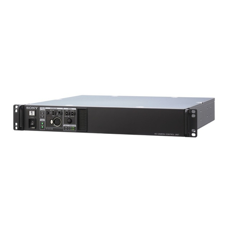
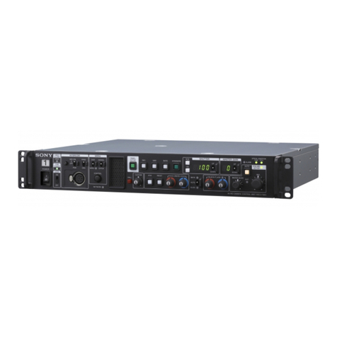
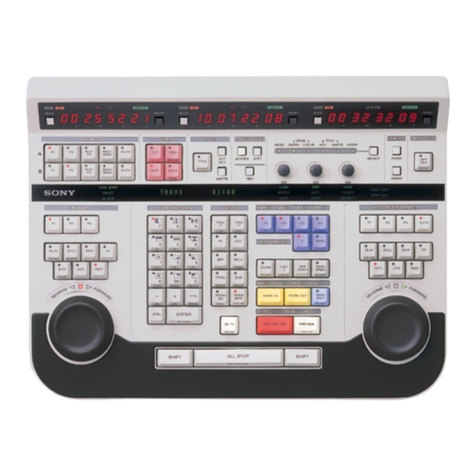
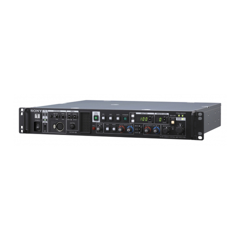
Sony PVE-500 User manual

01993
by
Sony Corporation

For the customers in Europe
This productwith the CEmarkinqcornplieswith boththe
EMC Directive (891336lEEC) and the iowVoltage
TO
prevent fire or shock hazard, do not
Directive(73123lEEC) issuedby the Commissionof the
expose the unit to rain or moist~re.
EuropeanCommunity.
This symbol 1s intended to alert the
user to the presence of uninsulated
"dangerous voltage" within the
product's enciosure that may be of
sufflcient magnitude to constitutea
risk ofelectric shock to persons
This symbol is intendedto alert the
user to the presence of important
operatingand maintenance(servicing)
instructionsin the literature
accompanyingthe appliance
For
customers
in
the
U.S.A.
WARNING
This equipment has beentested and found to comply
with the limits for a Class
A
digitaldevice,pursuantto
Part 15ofthe FCC Rules These limits are designed to
providereasonable protectioriagainst harmful
interference when the equipment is operatedina
commercialenvironment. This equipment generates,
uses, and can radiate radiofrequency eriergy and,
if
no!
installedand usedinaccordancewith the instruction
manual, may cause harmfuiinterferenceto radio
communications Operationof this equipment in a
residentialarea is likelyto cause harmfuiinterference in
which case the user will be requiredto correct the
interference at his own expense.
You are cautioned that any changes or modificationsnot
exptesslyapproved inthis manual couldvoid your
authority to operate this equipment,,
Compliance with these directives implies conformityto
the followingEuropeanstandards:
a
EN60065: ProductSafety
EN55103-1: Electromagnetic interference(Emission)
EN55103-2: ElectromagneticSusceptibiiity (Imrnunity)
This product is inlendedfor use inthe following
Electromagnetic Environment(s):
El(residential), E2(cornmercialand light industrial), E3
(urbanoutdoors) arid E4 (controlledEMC environment,
ex TV studio)
Pour les clientseuropéens
Ce produit portarit la marque CE es1conforme
a
lafois
a
la Directivesur lacompatibilité électromagnétique (EMC)
(8913361CEE) et
a
la Directivesur les bassestensions
(73123lCEE)émises par la Commission de la
Communauté européenne,
Laconformite
a
ces directives impliquelaconformité aux
normes européennes suivantes:
EN60065: Securité des produits
EN55103-1: Interférences électrornagnétiques
(emission)
EN55103-2: Sensibilité électromagnetique (immunité)
Ce produitest prevupour etre utilisé dans les
envirorinements électromagnétiquessuivants:
El
(residentiel). E2 (cornmercialet industrielégere),E3
(urbainexterieur)et E4 (environnement EMC contr6lé
ex studio de télevision).
Für Kunden
in
Europa
Dieses Produkt besitzt die CE-Kennzeichnung underfüllt
sowohl die EMV-Direktive(891336lEEC) als auch die
DirektiveNiederspannung (73123lEEC) der EG-
Kommission,,
Die Erfüllungdieser Direktivenbedeutet Konformitatfür
die folgendenEuropaischenNormen:
EN60065: Produktsicherheit
EN55103-1: Elektromagnetische lnterferenz(Ernission)
EN55103-2: ElektromagnetischeEmpfindlichkeit
(Immunitat)
Dieses Produkt ist für den Einsatz unter folgenden
elektromagnetischen Bedingungenausgelegt:
El(Wohnbereich), E2(kommerzieiier und in
beschranktem Mane industrieller Bereich), E3
(Stadtbereichim Freien)und E4 (kontrollierter EMV.
Bereich,
z
B Fernsehstudio),
The shieldedinterfacecable reconimendedinthis
manual must be usedwiththis equipment inorder to
comply with the limits for a digitaldevice pursuant to
Subpart B of Part 15of FCC ruies


About tliis Manual
................................................................................
3
(E)
Principal Features
...........................................................................
1-2
(E)
Optional Accessories
..........................................................................
1-4
(E)
...................................................
Control Panel
..............................
..
22
(E)
Connector Panel
.............................................................................
2-13
(E)
..........................................................................................
Precautions
3-2
(E)
.......................................................................................
Connections
3
(E)
....................................................................
Preparations for Editing
3
(E)
. .
..................
....
PVE-500 Setup (Ini~ialization)
....
, , , , , ,
..
, ,
.3-8
(E)
Ivleasuring Sta~tDel
-14
(E)
Prepaiing Tapes for
-
15
(E.)
................................................................
StandardEditing Session
42
(E)
.....................................................................
Selecting the Edit Mode
43
(E)
..........................................................................
Selecting the Player
4-5
(E)
............................................................................
Setting Edit Points
4-6
(E)
.............................................
Confirmingand Adjusting Edit Points
4-9
(E)
..........................................................................
Previewing the Edit
4-11
(E)
............................................................................
Executing the Edit
42
(E)
..........................................................................
Reviewing the Edit
43
(E)
.................................................................................................
Outline
5-2
(E)
.....................................
.............
Selecting FROM andTOSources
...
5-4
(E)
............................................................................
Setting Edit Points
5
(E)
..................................................................
Setting a Transition Time
57
(E)
...................................
Chapter
6
Controlling tlie DFS-5UU Siiapsliot Fiinction
6-2
(1.1)
........................
Advanced Editing
Controlling the DFS-500 During an A-Rol1Edit
6-I(I)
(1:)
Previcwing Immediately After Setting IN Points
........................................................................
-
Quiclc Editing
6
(1:)
......
Kesuniing Edit After Setting Player IN Poini
-
Uutt Editing
6-1
(E)
....................................................................
Using Aiixiliary Soiirces
6-5
(E)
.......
Setting Separ~teAudio and Video IN Points
-
Split Editiiig
6-7
(E)
............
Editing Still :ind Variable-Speed Playback
--
1)T Editing
6-9
(E)
Setting Transition Points During I'revie\v or Edits
..............................................................
..-SYNC Rol1 Editing
6
(1:)
...............
Controlling Externa1 Equipment via tlie GPI interface
6-13
(E)
.................................................................................
Rlnnual Editing
6-11
(E)
Contents
l
'
(E)

Contents
Outline
.................................................................................................
7
(E)
Registering an Edit (Interna1EDL Mode Only)
..............................
7-5
(E)
Recalling an Edit (Interna1EDL Mode Only)
.................................
7-6
(E)
............................................................
Adjusting and Deleting Edits
7
(E)
Uploading/Downloading the EDL (Interna1EDL Mode Only)
......
7-8
(E)
Error Messages
.................................................................................
A (E)
In Case of Trouble
............................................................................
A-3 (E)
Specifications
....................................................................................
A-4 (E)
Optional Accessorie
-5
(E)
Recommended Equi
-5
(E)
GIossary
..............................................................................................
A
(E)
Index
..................................................................................................
1-1
(E)

This section describes the organization of this manual and some conventions of
notation used
lntended audience
This manual is a guide to the PVE-500 editing control unit.
It is intended to he read by persons responsible for the operation of professional
video equipment, for example, at cable television stations and cotporate production
facilities. Therefore it assumes that readers will be familiar with the basic concepts
of video editing and have some experience in operating professional video
equipment.
Manual organization
The organization of this manual is as follows
Chapter
1
Outline
Explains the principal features of the unit and optional accessories
Chapter
2
Namesand Functionsof Parts
Briefly explains tlie function of each of the switches, controls, and connectors on
the control and connector panels
Persons already familia with p~ofessionalor broadcast editing equipment can
obtain a general grasp of the unit's capabilities by reading through this chapter
Chapter
3
Preparations
Covers matters which you need to know before using the unit, such as how to
connect externa1equipment to this unit in order to configure a complete editing
system, and preparations to make before stating to edit.
Chapter
4
Basic Editing
-
Cut Edits
Explains how to perform basic cut edits, using one player and one recotder, for
instantaneous switching between program sources.
Chapter
5
Editingwith Two Players
-
AIB Roll Edits
Explains how to perform
A/B
rol1 edits in which you can add special effects while
switching between the playback signals of two players, using a video switcher and
an audio mixer connected to this unit
Chapter
6
Advanced Edíting
Explains advanced techniques not covered in previous chapters
Chapter
7
Managing Edit Data
-
The Edit Decision List (EDL)
Explains how to save settings made in order to execute an automatic edit, and how
to recall the settings and use them again.
About
this
Manual
1
3
(E)

About
this
Manual
Appendix
Contains a list oferror messages with instructions on how to respond, a list of steps
to take when you suspect ttouble with tlie unit, specifications, anda glossary of
teclinical teims used in this manual
Conventions
Button names
As shown in the example below, some of the buttons on this unit have two
functions, depending on whethei tliey are pressed alone or in combination with the
ENTRY
button The two hnctions are indicated on the top and front sides of the
button.
indicator (LED)
PLAY button
When piessedalone, this button functionsas the PLAY button
This manual ielers to it simply as the PLAY button
%STOP (ENTRY
+
PLAY) bunon
When pressed together with the ENTRY button. this buttan
functions as the STOP bunon This manual refersto it as
the STOP (ENTRY
+
PLAY) button. with the keys to press
indicated in parentheses
Controlpanel illustrations
Tlie numbers of buttons and switches in illustrations of the control panel
correspond to steps in the procedure under discussion In order to keep the
illustrations simple,frequently used buttons are sometimes mentioned in the text
b~ttnot numbered in the illustrations
Cross references
Referentes
to othe~manuals or to sections of this manual containing related
information appear in italics
Technical terms
Technical terms are explained in a glossary in the Appendix to this manual
4
(E)
/
Aboul this Manual

Tiiis
cliaptei explainsthe piincipal feahlies of ihe iinit and
opiional accessoiies
Principal Features
..................................
~~
.....................
1-2
(E)
Optional Accessories
....................................................
1-4
(E)

The PVE-500 is an electronic editing control unit which allows you to perform
advanced editing easily and efficiently
You can connect a video switcher, an audio mixer, and up to three V?Rs to
configure an
A/T3
rol1 editing system The principal features of the unit are as
follows
Controls up to three VTRs
You can control two players and one recorder by remote control from the control
panel of this unit The control panel features independent search dials and control
buttons for the players and the recorder, allowing you to locate edit points quickly
and precisely
Three time counters
There are three time counters, allowing you to view time count data for two players
and one ~ecordersimultaneously
Video switcher coritrol
You can connect video switchers equipped with a 9-pin serial interface, such as
DFS-500 series or BVS-3000 series video switchers, using the optional9-pin
remote cable. Remote control of the video switcher allows you to:
*
execute automatic transitions fOr special effects when switching between the
playhack of selected players,
o
control the DFS-500 snapshot function, for automatic storing and recalling of
snapshots in coordination with edits stored in this unit.
Audio mixer control
You can connect a VSP-AóOO, MXP-290, orMXP-390 series audio mixer, or
another audio mixer.equipped with a 15-pin parallel or 9-pin serial inte~.face,using
the optional mixer control cable or a 9-pin remote cable. Remote control of,the
audio mixe~.allows you to switch the audio signals of'selected players and to
control automatic transition effects.
A/B
rol1editing
You can create rol1 effects such as wipes and dissolves. The A and
B
signals
can be selected from a total of five sources, including two players and three
auxiliary input sources.
SYNC
rol1editing
You can synchronize two player VTRs to execute effects automatically at specified
edit points.
Flexibleedit modes
You can choose between assemble mode, for simultaneous editing of video and
two audio channels, or insert mode, which allows you to edit video and audio
separately orin combination. In insert mode, you can specify separate
IN
points
(edit start points) for audio and video (split editing).
1-2
(E)
1
Chapter
1
Outline

DynamicTracking (DT)') for variable-speed editing
If your player supports dynamic tracking, you can edit freeze frame os variable
speed playhack.
GP12)output
You can output trigger signals to control external equipment when you execute an
edit.
Edit DecisionList
You can register data for up to 100edits in an edit decision list (EDL)stored in the
unit's internal memory (internal EDL mode). Interna1EDL data can be recalled
and changed at any time. It remains in the unit's internal memory for at least 100
hours after the power is turned off (provided that the unit has been powered on for
at least two hours). Tosave edit data permanently, you can connect a personal
computesosother external 110device. You can also choose to output edit data to
the external 110device each time you execute an automatic edit (external EDL.
mode).
Referencevideo signals for precisesynchronization
=
The unit can use reference video signals for precise synchronization If you set the
75-ohm terminator switch to OFF, refetence video signal input can he output to
other equipment using a T connector
Start delay measurement
The unit aiitomatically measures the amount of time which a connected VTR
requires to achieve stahle tape movement after receiving a start command
Information for each VTR is stored in the unit's internal memory It remains
available for at least 100hours after the unit is turned off (provided that the unit
has been powered on for at least two hours)
Easy setup and initialization
Slide switches ate available on the front panel for easy setting and selection oftime
codes, CTLcounts, prerol13)times, and synchronization modes Less frequently
used settings are made using the semch dials and a setup menu.
Error messages
The unit alerts you to mistaken operations with a warning sound and a concise
error message.
Rack mounting
With the RMM-500 control panel mount adaptor, you can mount this unit in a
standard EIA4)19-inchrack or editing operation desk.
1)
DT
is at~ademarkof Sony Corporation
4)
EIA: ElectionicIndustriesAssociation
2)
GPI: General Purpose Interface
3)
Preioll: An operation in which a
VTR
begins to run
its tape from apoint a few seconds in advance of the
edit IN point, enabling the tape to reach
a
steady
speed at the edit IN point and to synchionizewith
other video tapes
Chapler
i
ouiline
1
1-3
(E)

Optional accessories such as the followingare available for purchase for use with
this iinit
RMM-500
control panel mount adaptor
An adaptor which allows you to mount the unit in a standard EIA 19-inch tack or
editing desk For details please contact a Sony sales representative
RMM-SO0
RMM-500
controlpanelmauntadaptar
RCC-5AA
mixer controlcable
A 9-pinIl5-pin conversion cable fo~use in connecting an audio mixer equipped
with a 15-pinparailel interface (VSP-A600, MXP-290, MXP-P390, etc.) to this
unit.
Cables for use in connecting a video switcher or an audio mixer equipped with a
9-
pin serial interface (MXP-S390, etc.) to this unit.
1.4
(E)
/
Chapter
1
Outline

nt~olarid connectoi
......................
2-13
(E)

The control panel is configured as follows. Uetailed inforrnation fo~each of the
conirols is given on the pages indicated in parentheses.
Operalion mode control Edit
numberltransilionlduialion
section (page P3(E)) setting anddisplay seclion (page 2-6(E))
Player 1 time counter
seclion (page 2-4(E))
I
I
Player
2
time counter Recordertime counter
section (page 2-5(E)) section (page 2-5(E))
Source selection-
section (page 2-6(E))
Powerswitch
-
,415
rol1setting Edit point sening section
section (page 2-7(EJ)
Edit mode setting
section (page 2-7(E))
Manual editinglsetup
section (page PB(E))
I
Player operatioiicontrol Autornaticediting section Recordeioperatioii control
section (page 2-9(E)) (page 2-12(E)) section (page 2-lo(€))
Control panel
2-2
(E)
/
Chapler
2
Namesand Funclionsof Parls

Operation modecontrol section
I
1
Operationmodecontrolcection
@
LEARNbutton
Press to automatically measure the start delays of
the connected VTRs.
@
PREROLL(prerolltime) selector
Set the preroll time to
7
(or 10)seconds,
5
seconds,
or
3
seconds If yoii set this selector to
7
seconds,
the preroll time will be either
7
or
10
seconds,
depending on the setting made using the setup
menu
SYNCHRO (synchronízation)selector
Determines whether or not to synchranize and use
color framing.
ONICF:
Synchronizes and uses color framing.
T1iis yields a stable picture, hut editing
precision isslightly lower.
ON:
Synchronizes but does not use color framing.
OPF:
Does not synchronize.
@
TCIRTCICTL(edit reference)selectors
(for player
1,
player
2,
and recorder)
Determine the time counter display format for
player
1
(Pl),player
2
(P2), and the recorder (R)
TC:
Displays the recorded time code (absolute
value). The display is not reset even if you
press the RESET button.
RTC:
Displays an incremented or decremented
time code after reset (relative value) Reset
when you press the RESET button.
CTL:
Displays a CTLpulse count after reset.
Reset when you press the RESET button.
Chapter
2
Names
and
Funcllons
of
f'ads
2-3
(E)

Control
Panel
Player
1
time countersection
SERVO indicatol
IN
indicator
l
I
Player
1
time counter seciion
@
RESET
button
Press to reset the time counter
O
and to reset edit
points
@
SERVO
indicator (green)
Lights when player
1
is running with the servo
locked.
@
IN
(edit start point) indicator (red)
Lights when an
IN
point has been set for player 1,
and fiashes to indicate that an
iN
point needs to be
set Flashes at high speed while an
IN
point or
duration (distance from an
IN
point to an OUT
point) is being displayed in the time counter
O
O
OUT
(editend point) indicator (red)
Lights when an OUT point has been set for player
1,
and flashes to indicate that an OUT poirit needs
to be set. Flashes at high speed while an OUT
point or duration is being displayed in the time
counter
O
@Time counter
Depending upon the setting of the TC/RTC/CTL
selector, displays an absolute or relative time code
for player 1,o1a control signal count During setup
with the setup menu, displays the menu item
number
Erzor messages are also displayed in this time
counter
2-4
(E)
1
Chapter
2
Narnesand Funcfions ol Parts

Player
2
tíme counter section
SERVO
indicator
IN
indicator
L
l
Player
2
lime counler section
During setup with the setup menu, the time counter
Orher birffoii.rnild iiidicafo~rliniie the rniiiefiriictio~i.sas
@
displays an abhreviated item title
rlio,reeiplaiiied iii thep~evioiirrectiotl "Plnyrr
1
tiiile
COL(II~~I
secfioil
"
Recorder time counter section
RESET
button
SERVO
indicator
lN
indicator
Recordertime counter seclion
FIOIIIrlie RESET Dlrtroii
@
to the OUT i~idicntor
@,
@TOTAL (tonal runningtime)
button
and
ihere buttoiir niid bidicaroi:~/tuve snriie furiction.s as
indicator(red)
fhoree,rplnined iinder ite11i.r to
O
iii "Pln,yer
1
tilile
Press the TOTAL button if you want to display the
coirriter sectioii
"
(page2-4(Ej).
recorder's total running time in tlie time counter.
-
The indicator begins to flash when you press the
@Time counter
button. Press the button again to restore the time
Dependiug upon the settings of the TCIRTCICTL countes's original display.
selector and tlie TOTAL button
@,
displays an
If
you want to reset the total running time, press
absolute or relative time code, a CTL signal count, tbe RESET button
@
while the total niuning time
or the recordes's total mnning time. During setup is displayed in the time counter.
with the setup menu, displays the setup item data.
Error messages are also displayed in this time
counter
Chapter
2
Narnes and Funclions
Ot
Parls
2-5
(E)

Control Panel
6:
Edit
number/transition/duration
setting and display section
i
Edit numberltransitionldurationsetting and display seclion
@
EDlT NO.ITRANSIDUR
(edit numberl
@
EDlT NO.fiRANS/DUR
display
transitionlduration)buttons
To inte~pretthe number in this display, check the
Use to set the edit number, effect transition time, TRANS button in the
AIB
rol1 setting section If
or the du~ationof an edit segment.The three the TRANS button is lit, this display shows an
buttons correspond to the three digits in the display effect transition time. If the button is flashing, the
0.
display shows an edit duration.
If
the button is out,
the display shows the current edit number.
-
Source selection section
@
FROMTOIAUX3
(ENTRY
t
FROMTO)
button
@
PIIAUXI
(ENIRY
+
PI)
bunon
@
FROM
TO
indicators
@
PZAUX2 (ENTRY
+
PZ)
bunon
Source selection seclion
@
PlIAUX1(ENTRY
+
P1)
button
P1
(player
1):
Ptess to select the VTR connected
to the PLAYER 1connector as the source The
button lights when you press it
AUXl (ENTRY
+
Pl)(auxiliary source 1): Press
to select the equipment connected to the AUXl
connector as the source, for example, a camera
connected to a video switcher
@
P21AUX2 (ENTRY
+
P2)
button
P2(player 2): Press to select the VTR connected
to the PLAYER
2
connector as the source. The
button lights when you pI.ess it.
AUX2 (ENTRY
+
P2)(auxiliary source 2): Press
to select the equipment connected to the
AUX2
connector as the source, for example a camera
connected to a video switcher.
@
FROMTOIAUX3 (ENTRY
+
FROMTO)
button
FROMTO: Press to change the FROM source
(source before a transition) or the TO source
(source after a transition).
AUX3 (ENTRY
+
FROMTO)(auxiliary source
3):
Press to select the equipment connected to
the
AUX3
connector as the source, for example
a camela connected to a video switcher.
@
FROMTO
indicators
Green: Indicate whether the next operation will be
fOr the FROM source or the TO source.
Red: Indicate the cu~~entlyselected FROM and
TOsources. Flash when the selected source
players are in DT playback mode.
2-6
(E)
1
Chapler
2
Narnes and Funcfions
of
Pans

Al6
rol1setting section
l
/
@
NB
ISYNC (ENTRY
+
NB)
button
l
AIB
roil setting section
@
NBISYNC(ENTRY
+
NB)button
@
TRANSIDUR (ENTRY
+
TRANS) button
A/B
(AIB
roll):
Press to select
A/B
1011
mode.
TRANS (transition):
Press to set the effect
The button lights. transition time. The biitton lights.
SYNC (ENTRY
+
AíB)(SYNC roll):
Press to
DUR (ENTRY
+
TRANS)(duration):
Press to
select
SYNC
rol1 mode. The button begins to set the edit duration. The button begins to
flash. flash.
Edit
mode setting section
@
V
button
I
Edit mode setting section
@
ASMBL (assemble) button @Al(audio 1) button
Piess to select assemble mode. The button lights Press to select channel
1
audio inseri mode The
If any of the inse~tmode buttons are lit, piess them button lights
If
the
ASMBL
button is lit, press it
to exit insert mode before pressing this button. to exit assemble mode befo~epressing this button
For i~ifor~iiationaboiit the arreiiible aiid iiisert nrodes,
see "Selectiiigtlie Edit Mode" (page
4-.?(E)).
@
A2
(audioi2)button
Press to select channel2 audio insert mode. The
@
V
(video) button
button lights. If the
ASMBL
button is lit, press it
Press to select video inseit mode The button to exit assemble mode before pressing this button.
lights.
If
the
ASMBL
button is lit, pIess it to exit
assemble mode before pressing this button
Chapter
2
Namesand Functions
ol
PartS
2.7
(E)

Control Panel
*##--'S*
-
.
,-
S
w>..:+#'~,-*
~~~:L-~~*~>~*-,::~~~~~~~~m~~&~"~**~~,#.~~"~~~?~~~~~~~~~~~g
Manualeditinglsetup section
i
@
RECISTORE (ENTRY
+
REC)
button
@
EDITiSETUP (ENTRY
+
EDIT)
button
Manual
editing/selup
section
@
RECISTORE(ENTRY
+
REC) button
REC
(record):
Press to put the unit into
E-E
mode
1).
While you keep the button pressed, the
recorder's video, audio
1
and audio
2
input
signals are output to the monitor but not
recorded.
For manual editing, press this button togethei
with the PLAY hutton
CD
in the recorder
operation control section at the point where you
wish to begin recording.
STORE (ENTRY
+
REC):
If
the unit is in
internal
EDL
mode
(see
pnge
7-3(E)),
edit data
is saved in the unit's internal memory.
If
this
button is pressed while you are using the setup
menu, setup data brthe current menu item is
written to the unit's EEPROM2).
@
EDITISETUP(ENTRY
+
EDIT)button
EDIT:
Press to put the unit into
E-E
mode, using
the edit mode set witli the edit mode buttons.
While you keep the button pressed, the
recorder's input signals selected by the edit
rnode are output to the monitor but not
recorded.
For manual editing, press this blitton togethei
with the PLAY button
CD
in the recorder
operation control section at the point where you
wish to begin recording.
SETUP (ENTRY
+
EDIT):
Press to cal1up the
sexch dial setup menir (setup mode).
1)
E-E: Electric-to-Electric
2)
EEPROM: Electiically erasable programmableROM
2-8
(E)
1
Chapter
2
Names
and
Functions
of
Pans

player operation control sectian
@
PLAYISTOP
(ENTRY
+
PLAY)
button
@
STILUSTB OFF
(ENTRY
+
STILL)
buiion
&)
REWIEJECT
(ENTRY
+
REW)
button
@
FFNAR
(ENTRY
+
FF)
button
Q1)
Direction indicators
@
Search dial
L
I
Player operationcontrol sectlon
@
PLAYISTOP(ENTRY
+
PLAY) button
Bi)
Directionindicators
PLAY: Plays the tape Light to show the tape direction The indicators go
STOP(ENTRY
+
PLAY): Stops the tape out wlien the ~initis in standby off mode
@
STILUSTB OFF (ENTRY
+
STILL) button
STILL: Gives a still picture.
STBOFF(ENTRY
+
STILL)(standby
offl: Press when the unit is paused or
displaying a still picture and yon want to exit
standby mode (standhy off)
@
REWIEJECT(ENTRY
+
REW) button
REW (rewind): Rewinds the tape.
EJECT (ENTRY
+
REW): Ejects the cassette
@
FFNAR (ENTRY
+
FF) button
FF(fast forward): Fast forwards the tape.
VAR (ENTRY
c
FF)(variable): When using a
player which suppo~tsDynamic Tracking (DT),
press the search dial to bring it to the raised
position, then press this button. You will be
able to edit noiseless, varlable-speed playback
(DTediting) The di~ectionindicator
0
flash in
red while you are running a tape in variahle-
speed mode.
@
Search dial
Controls the movement of the tape. Use while
searching for an edit point or during DT playback.
Tlie dial has two positions: a raised position for
shuttle mode playback and a depressed position for
jog mode playback. Press the dial to inove from
one mode to tlie other.
If your player supports Dynamic Traclcing (DT)
playback, you can use this dial to perform
noiseless editing of variable-speed playback. With
the search dial in the raised position, press the
VAR
(ENTRY
+
FF) button
Q3
to enter variable
playback mode.
Chapier
2
Narnes and FunclioncofParts
2.9
(E)

Control Panel
...
.....
...
....
,..
....
.,,.,.
.,:,
,
.
,
.
,..
.
.,,.,.
--
,
..
-
. .
,
..
._-_.-'-A
--i
Recorderoperation control section
@
PLAYISTOP-
(ENTRY
+
PL.AY) button
@
STILUSTB OFF
(ENTRY
+
STILL) button
(ENTRY
t
REW)button
(ENTRY
+
FF) button
.-
l
-
l
.--
-
.-
Recorder operationcontrol section
N
z
-
Ihese controlr hove tlie snine fiiricriot~sas tliose
(D'T),
yori can irse irfor rioi~elesr,variable-speed
a
m
esplaiized iti "Plciyei,operarioii corirrol sectioti
"
(page playback
6
2-9(E)J.
[f
yotir recorder srrpportr Dyriarz~icTrcickizlg
Edit point setting section
Q)
/BS (ENTRY
+
O
)
button
1
Í
Qi)
O
IFS (ENTRY
+
O
)
buttan
@
AUDlO SPL.IT/SPEED
'
LAST EDITICLEAR
(ENTRYI. AUDlOSPLIT) button
1
//
r"
(ENTRY
+
LAST EDIT) button
@
Recorder INbutton
-
@
Recorder OUT button
(ENTRY
+
GOTO)
-
@
ENTRY button
Edit pointsetting seclion
Q)
IBS(ENTRY
+a
)
button
together with both the
Di
and
OUT
buttons
(Trim
-):
Press this button together with the The
IN
and
OUT
points will be moved one
IN
button
a,
@
or
OUT
button
CD,
63
when you frame back
want to move an
iN
or
OUT
point one fiame
BS
(ENTRY
+
a)(previous
edit):
In interna1
back Keep the buttons pressed to execute this
EDL
mode, calls up the previous edit Keep
function continuously When you want to shift this button pressed to execute this function
an entire edit segment, press this button continuously.
2-1
0
(E)
/
Chapler
2
Narnesand Functionsol
Parts
Other manuals for PVE-500
1
Table of contents
Other Sony Control Unit manuals

Sony
Sony HXCU-FB80 4K/HD User manual

Sony
Sony BVE-700 User manual

Sony
Sony HXCU-FB80 User manual

Sony
Sony SVRM-911 User manual

Sony
Sony FCB-EV7310 User manual

Sony
Sony KCC-PCH User manual

Sony
Sony HXCU-100 User manual

Sony
Sony BKS-R1617 User manual

Sony
Sony HDCU-950 Manual

Sony
Sony HDCU-700A Configuration guide
Popular Control Unit manuals by other brands

Leonard
Leonard 170-LF INSTALLATION ADJUSTMENT SERVICE

Leafield Marine
Leafield Marine C7 SERVICE ADVICE

Johnson Controls
Johnson Controls G77 Series Technical bulletin

Val-Matic
Val-Matic 100VB Operation, maintenance and installation manual

FNW
FNW HPA Installation, operation and maintenance instructions

Azbil
Azbil ACTIVAL VY519 J Series Specifications & instructions