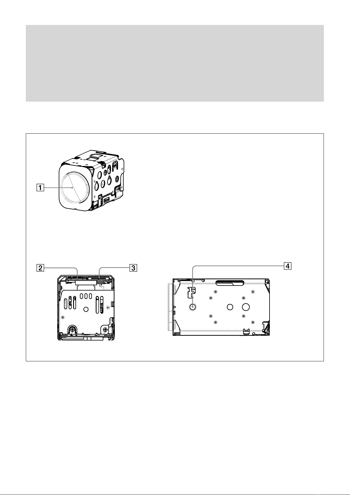
Sony FCB-EV7300 User manual

2014 Sony Corporation
FCB-EH6500(GB) A-EEP-100-11(1)
Color Camera Module
FCB-EV7300
A-EW1-100-13(1)
Technical Manual

2
FCB-EH6500(GB) A-EEP-100-11(1)
Table of Contents
Features............................................................................. 3
Precautions ....................................................................... 4
Locations of Controls ....................................................... 6
Basic Functions ................................................................. 7
Overview of Functions.....................................................................7
User’s Updating............................................................................... 21
Eclipse................................................................................................. 24
Spectral Sensitivity Characteristics .......................................... 24
Initial Settings, Custom Preset and Backup .......................... 25
Mode Condition.............................................................................. 27
Command List.................................................................30
VISCA/RS-232C Commands ........................................................ 30
FCB Camera Commands .............................................................. 36
Specifications .................................................................57

3
Overview
FCB-EH6500(GB) A-EEP-100-11(1)
Features
•Imager
This camera uses a 1/2.8" “Exmor” CMOS
(complementary metal-oxide semiconductor) image
sensor (approx. 2.14 million effective pixels) that
supports FULL HD (high definition) to produce high-
quality images.
•ISP
Using the newly developed image signal processor
(ISP), the following images can be obtained.
- Full HD 60fps output image
- Low focal plane image using the high-speed
readout of imager
The following functions are provided.
- Advanced Noise Reduction (NR), Wide
Dynamic Range (WD) and Image Stabilizer
functions
- Newly provided tone correction (Visibility
Enhancer) and Defog functions
•Lens
The camera is equipped with a bright lens with 20×
optical zoom and F1.6 aperture (optical zoom +
digital zoom = 240×).
With consideration given environmental protection,
this module is designed to operate with low power
consumption and also incorporates lead-free and
halogen-free circuit boards.

4
Overview
FCB-EH6500(GB) A-EEP-100-11(1)
Software
Use of the demonstration software developed by Sony
Corporation or use of the software with customer
developed application software may damage hardware,
the application program or the camera. Sony
Corporation is not liable for any damages under these
conditions.
Operation
Start the camera control software on your computer
after you turn on the camera and the image is displayed.
Operation and storage locations
Do not shoot images that are extremely bright (e.g.,
light sources, the sun, etc.) for long periods of time. Do
not use or store the camera in the following extreme
conditions:
•Extremely hot or cold places (operating temperature
–5 ˚C to +60 ˚C (23 ˚F to 140 ˚F))
•Close to generators of powerful electromagnetic
radiation such as radio or TV transmitters
•Where it is subject to fluorescent light reflections
•Where it is subject to unstable (flickering, etc.)
lighting conditions
•Where it is subject to strong vibration
•Where it is subject to radiation from laser beams
Care of the unit
Remove dust or dirt on the surface of the lens with a
blower (commercially available).
Other
•Design and specifications are subject to change
without notice.
•Do not apply excessive voltage. (Use only the specified
voltage.) Otherwise, you may get an electric shock or
a fire may occur.
•The CMOS image sensor and IC included in this
camera may break if exposed to static electricity.
When directly handling this camera, wear an
antistatic strap, spread a conductive sheet or similar
item under your workbench, and take measures to
eliminate static electricity.
Precautions
•In case of abnormal operation, contact your
authorized Sony dealer or the store where you
purchased the product.
Phenomena specific to CMOS image sensors
The following phenomena that may appear in images
are specific to CMOS image sensors. They do not
indicate malfunctions.
Rolling shutter
As CMOS image sensors use shutters that capture
images line-by-line, there is a slight time difference
between the top and bottom of an image. As a result,
images may appear skewed if the camera is moved.
White flecks
Although the CMOS image sensors are produced with
high-precision technologies, fine white flecks may be
generated on the screen in rare cases, caused by cosmic
rays, etc.
This is related to the principle of CMOS image sensors
and is not a malfunction.
The white flecks especially tend to be seen in the
following cases:
•when operating at a high environmental temperature
•when you have raised the master gain (sensitivity)
•when operating in Slow-Shutter mode
Aliasing
When fine patterns, stripes, or lines are shot, they may
appear jagged or flicker.
Phenomena Specific to Lenses
Ghosting
If a strong light source (e.g., the sun) exists near the
incidence angle of the lens, bright spots may appear in
the image due to diffuse reflection within the lens.
About the trademark
“Exmor” and “StableZoom” are trademarks of Sony
Corporation.

5
Overview
FCB-EH6500(GB) A-EEP-100-11(1)
Notification on BSD License Application
Software
Please read the contents of description below at least
once.
FILE:sha2.c,sha2.h,sha2prog.c,sha2speed.c,sha2test.pl
AUTHOR: Aaron D. Gifford - http://www.aarongifford.com/
Copyright (c) 2000-2001, Aaron D. Gifford All rights
reserved.
Redistribution and use in source and binary forms, with or
without modification, are permitted provided that the
following conditions are met:
1. Redistributions of source code must retain the above
copyright notice, this list of conditions and the following
disclaimer.
2. Redistributions in binary form must reproduce the above
copyright notice, this list of conditions and the following
disclaimer in the documentation and/or other materials
provided with the distribution.
3. Neither the name of the copyright holder nor the names of
contributors may be used to endorse or promote products
derived from this software without specific prior written
permission.
THIS SOFTWARE IS PROVIDED BY THE AUTHOR AND
CONTRIBUTOR(S) “AS IS” AND ANY EXPRESS OR
IMPLIED WARRANTIES, INCLUDING, BUT NOT
LIMITED TO, THE IMPLIED WARRANTIES OF
MERCHANTABILITY AND FITNESS FOR A
PARTICULAR PURPOSE ARE DISCLAIMED. IN NO
EVENT SHALL THE AUTHOR OR CONTRIBUTOR(S) BE
LIABLE FOR ANY DIRECT, INDIRECT, INCIDENTAL,
SPECIAL, EXEMPLARY, OR CONSEQUENTIAL
DAMAGES (INCLUDING, BUT NOT LIMITED TO,
PROCUREMENT OF SUBSTITUTE GOODS OR
SERVICES; LOSS OF USE, DATA, OR PROFITS; OR
BUSINESS INTERRUPTION) HOWEVER CAUSED AND
ON ANY THEORY OF LIABILITY, WHETHER IN
CONTRACT, STRICT LIABILITY, OR TORT (INCLUDING
NEGLIGENCE OR OTHERWISE) ARISING IN ANY WAY
OUT OF THE USE OF THIS SOFTWARE, EVEN IF
ADVISED OF THE POSSIBILITY OF SUCH DAMAGE.

6
Locations of Controls
FCB-EH6500(GB) A-EEP-100-11(1)
Locations of Controls
Lens
CN401 connector
CN501 connector
Tripod screw hole
When a tripod is used, please use 5 mm (7/32 in.) or less screw to attach it to the camera.
Also, please be sure to attach the tripod securely.
Front
Back Bottom

7
Basic Functions
FCB-EH6300(GB) A-E23-100-13(1)
Basic Functions
Overview of Functions
The camera control is performed by VISCA
Commands.
Timing Chart
As VISCA Command processing can only be carried
out one time in a Vertical cycle, it takes the maximum
1V cycle time for an Acknowledge/Completion to be
returned.
If the Command/Acknowledge/Completion
communication time can be less than the 1V cycle
time, then every 1V cycle can receive a Command.
Query Commands
General Commands
16 Byte
1) 1V cycle times on each Monitoring Mode and Shutter Speed.
Monitoring Mode
1080p/60 1080p/50
1080p/59.94 1080p/25
1080p/30 1080i/50
1080p/29.97 720p/50
1080i/60 720p/25
1080i/59.94
720p/60
720p/59.94
720p/30
720p/29.97
1/60 sec 1/50 sec
In general
• Power On/Off
Powers the camera on and off.
When the power is off, the camera is able to accept
the VISCA Commands although the screen is set
non-displayed.
• I/F Clear
Clears the Command buffer of the FCB camera.
• Address Set
VISCA is a protocol, which normally supports a daisy
chain of up to seven connected cameras via RS-232C
interface. In such cases, the address set command can
be used to assign addresses from 1 to 7 to each of the
seven cameras, allowing you to control the seven
cameras with the same personal computer.
Although the FCB camera does not support direct
connection of cameras in a daisy chain, be sure to use
the address set command to set the address whenever
a camera is connected for the first time.
• ID Write
Sets the camera ID.
• Mute
Blanks the screen and sends out a synchronizing
signal.
• Lens Initialize
Initializes the zoom and focus of the lens. Even when
power is turned on, it initializes the zoom and the
focus.

8
Basic Functions
FCB-EH6300(GB) A-E23-100-13(1)
Zoom
The FCB camera incorporates a 20× optical zoom lens
combined with a digital zoom function; this camera
allows you to zoom up to 240×.
•Optical 20×, f = 4.7 mm to 940 mm
(F 1.6 to F 3.5)
The horizontal angle of view is approximately 59.5
degrees (wide end) to 3.3 degrees (tele end).
Digital Zoom enlarges the center of the subject by
expanding each image in both the vertical and
horizontal directions. When 240× zoom is used, the
number of effective picture elements in each direction
reduces to 1/12 and the overall resolution deteriorates.
Zoom has the following modes.
Using Standard Mode
Using Variable Mode
There are eight levels of zoom speed.
In these standard and variable modes, it is necessary to send
Stop Command to stop the zoom operation.
Direct Mode
Setting the zoom position enables quick
movement to the designated position.
Digital Zoom
The Zoom Mode supports, a OFF, a Combined
Mode and a Separate Mode.
Combined Mode
This is the previously existing zoom method.
After the optical zoom has reached its
maximum level, the camera switches to Digital
Zoom Mode.
Separate Mode
In this mode, Optical Zoom and Digital Zoom
can be operated separately. You can use digital
zoom magnification at any time from within
any level of optical magnification.
About Continuous Zoom Position Reply
With ZoomDirect mode, or when zooming according
to a preset, the camera outputs zoom position data
when Continues Zoom Position Reply is set to On via a
command.
Continues Zoom Position Reply: y0 07 04 69 0p 0p 0q
0q 0q 0q FF
pp: D-Zoom Position
qqqq: Zoom Position
Focus
Focus has the following modes.
• Auto Focus Mode
The minimum focus distance is 10 mm at the optical
wide end and 1000 mm at the optical tele end, and is
independent of the digital zoom.
The Auto Focus (AF) function automatically adjusts
the focus position to maximise the high frequency
content of the picture in a center measurement area,
taking into consideration the high luminance and
strong contrast components.
- Normal AF Mode
This is the normal mode for AF operations.
- Interval AF Mode
The mode used for AF movements carried out at
particular intervals. The time intervals for AF
movements and for the timing of the stops can be
set in one-second increments using the Set Time
Command. The initial setting for both is set to 5
seconds.
- Zoom Trigger Mode
When zoom position is changed,it becomes AF
mode during the pre-set value (initial setting is set
to 5 seconds). Then it stops.
• AF Sensitivity
The switching of AF sensitivity can be set.
- Normal
Reaches the highest focus speed quickly. Use this
when shooting a subject that moves frequently.
Usually, this is the most appropriate mode.
- Low
Improves the stability of the focus. When the
lighting level is low, the AF function does not take
effect, even though the brightness varies,
contributing to a stable image.
• Manual Focus Mode
Manual Focus has both a Standard Mode and a
Variable Mode. Standard Mode focuses at a fixed rate
of speed. Variable Mode has eight speed levels.
In these standard and variable modes, it is necessary to send Stop
Command to stop the zoom operation.
• One Push Trigger Mode
When a Trigger Command is sent, the lens moves to
adjust the focus for the subject. The focus lens then
holds that position until the next Trigger Command is
input.
• Near Limit
Can be set in a range from 1000 (∞) to F000 (10 mm).
Initial setting: D000h (30 cm)

9
Basic Functions
FCB-EH6300(GB) A-E23-100-13(1)
White Balance (WB)
White Balance has the following modes.
• Auto
This mode computes the white balance value output
using color information from the entire screen. It
outputs the proper value using the color temperature
radiating from a black subject based on a range of
values from 2500K to 7500K.
This mode is the initial setting.
• ATW
Auto Tracing White balance (2000K to 10000K)
• Indoor
3200K Base Mode
• Outdoor
5800K Base Mode
• One Push WB
The One Push White Balance mode is a fixed white
balance mode that may be automatically readjusted
only at the request of the user (One Push Trigger),
assuming that a white subject, in correct lighting
conditions, and occupying more than 1/2 of the
image, is submitted to the camera.
One Push White Balance data is lost when the power
is turned off. If the power is turned off, reset One
Push White Balance.
• Manual WB
This is a mode that enables you to manually set the
control of R and B gain up to 256 steps.
• Outdoor Auto
This is an auto white balance mode specifically for
outdoors. It allows you to capture images with natural
white balance in the morning and evening.
• Sodium Vapor Lamp Auto
This is an auto white balance mode that is compatible
with sodium vapor lamps.
• Sodium Vapor Lamp
This is a fixed white balance mode specifically for
sodium vapor lamps.
• Sodium Vapor Lamp Outdoor Auto
This is an auto white balance mode specifically for
outdoors, which is compatible with sodium vapor
lamps.
Note
High-pressure sodium lamps are supported. Proper
white balance may not be captured for some subjects
when using low-pressure sodium lamps.
Auto Exposure Mode (AE)
A variety of AE functions are available for optimal
output of subjects in lighting conditions that range
from low to high.
• Full Auto
Iris, Gain and Shutter Speed can be set automatically.
• Gain Limit Setting
The gain limit can be set at the Full Auto, Shutter
Priority, Iris Priority, Bright, Spot Exposure and
Manual in the AE mode. Use this setting when you
want to obtain image in which signal-to-noise ratio is
particularly important.
• Shutter Priority1)
Adjust with Variable Shutter Speed (1/1 to 1/10,000
sec., 16 high-speed shutter speeds plus 6 low-speed
shutter speeds), Auto Iris and Gain.
1)Flicker in the East Japan area (50 Hz power supply frequency)
can be eliminated by setting shutter to 1/100s.
• Iris Priority
Adjust with Variable Iris (F1.6 to Close, 14 steps),
Auto Gain and Shutter speed
• Manual
Adjust with Variable Shutter, Iris and Gain
• Bright
Adjust with Variable Iris and Gain (Close to F1.6, 14
steps and F1.6 at 15 steps)
AE – Shutter Priority
The shutter speed can be set freely by the user to a total
of 22 steps – 16 high speeds and 6 low speeds. When
the slow shutter is set, the speed can be adjusted
according to subject brightness. The picture output is
read at a normal rate from the memory. The memory is
updated at a low rate from the CMOS. AF following
capability is lowered and also the number of frame to
be displayed is decreased.
In high speed mode, the shutter speed can be set up to
1/10,000s. The iris and gain are set automatically,
according to the brightness of the subject.

10
Basic Functions
FCB-EH6300(GB) A-E23-100-13(1)
MIN
MAX
AGC
CLOSE
OPEN
Iris
Gain
Dark Bright
Iris curve
Gain curve
Controlled
by gain
Controlled by Iris
Bright limit which controllable
for this unit
Data Iris Gain Data Iris Gain
1F F1.6 48.8 dB (28 step) 11 F1.6 0 dB (0 step)
1E F1.6 45.3 dB (26 step) 10 F2 0 dB (0 step)
1D F1.6 41.9 dB (24 step) 0F F2.4 0 dB (0 step)
1C F1.6 38.4 dB (22 step) 0E F2.8 0 dB (0 step)
1B F1.6 34.9 dB (20 step) 0D F3.4 0 dB (0 step)
1A F1.6 31.4 dB (18 step) 0C F4 0 dB (0 step)
19 F1.6 27.9 dB (16 step) 0B F4.8 0 dB (0 step)
18 F1.6 24.4 dB (14 step) 0A F5.6 0 dB (0 step)
17 F1.6 20.9 dB (12 step) 09 F6.8 0 dB (0 step)
16 F1.6 17.4 dB (10 step) 08 F8 0 dB (0 step)
15 F1.6 14 dB (8 step) 07 F9.6 0 dB (0 step)
14 F1.6 10.5 dB (6 step) 06 F11 0 dB (0 step)
13 F1.6 7 dB (4 step) 05 F14 0 dB (0 step)
12 F1.6 3.5 dB (2 step) 00
CLOSE
0 dB (0 step)
When switching from the Shutter Priority mode to the
Bright mode, the shutter speed set in the Shutter
Priority mode is maintained.
Spot Exposure Mode
In Full Auto AE, the level for the entire screen is
computed and the optimum Auto Iris and Gain levels
are determined. In Spot AE, a particular section of the
subject can be designated, and then that portion of the
image can be weighted and a value computed so that
Iris and Gain can be optimized to obtain an image.
For example, in an image with a lot of movement and
with varying levels of brightness, portions without
much change can be designated as such a “spot,” and
changes to the screen can be minimized in that area.
As shown in the diagram below, a range of 16 blocks
vertically and 16 blocks horizontally can be designated.
In the case where the center is designated (shown in
black), the level is computed along with a weighted
value for the surrounding block (shaded), including the
Data 60/59.94/30/29.97
mode
50/25 mode
15 1/10000 1/10000
14 1/6000 1/6000
13 1/4000 1/3500
12 1/3000 1/2500
11 1/2000 1/1750
10 1/1500 1/1250
0F 1/1000 1/1000
0E 1/725 1/600
0D 1/500 1/425
0C 1/350 1/300
0B 1/250 1/215
0A 1/180 1/150
09 1/125 1/120
08 1/100 1/100
07 1/90 1/75
06 1/60 1/50
05 1/30 1/25
04 1/15 1/12
03 1/8 1/6
02 1/4 1/3
01 1/2 1/2
00 1/1 1/1
AE – Iris Priority
The iris can be set freely by the user to 14 steps
between F1.6 and Close.
The gain and shutter speed are set automatically,
according to the brightness of the subject.
Data
Setting value
Data
Setting value
11 F1.6 0A F5.6
10 F2 09 F6.8
0F F2.4 08 F8
0E F2.8 07 F9.6
0D F3.4 06 F11
0C F4 05 F14
0B F4.8 00 CLOSE
AE – Manual
The shutter speed (22 steps), iris (14 steps) and gain
(15 steps) can be set freely by the user.
AE – Bright
The bright control function adjusts both gain and iris
using an internal algorithm, according to a brightness
level freely set by the user. Exposure is controlled by
gain when dark, and by iris when bright.
As both gain and iris are fixed, this mode is used when
exposing at a fixed camera sensitivity. When switching
from Full Auto or Shutter Priority Mode to Bright
Mode, the current status will be retained for a short
period of time.
Only when the AE mode is set to “Full Auto” or
“Shutter Priority,” can you switch it to “Bright.”

11
Basic Functions
FCB-EH6300(GB) A-E23-100-13(1)
specified portions; and then the Gain and Iris are set.
The value of the designated portions and the
surrounding areas should be calculated as 100%, the
rest should be set to 20%. The range of the Spot AE
frame is fixed to 5 blocks vertically and 4 blocks
horizontally.
(8,7)
Horizontal 16
Vertical 16
0
0
1
2
3
4
5
6
7
8
9
A
B
C
D
E
F
1 2 3 4 5 6 7 8 9 A B C D E F
Exposure Compensation
Exposure compensation is a function which offsets the
internal reference brightness level used in the AE
mode, by steps of 1.5 dB.
Data Step
Setting value
0E +7 +10.5 dB
0D +6 +9 dB
0C +5 +7.5 dB
0B +4 +6 dB
0A +3 +4.5 dB
09 +2 +3 dB
08 +1 +1.5 dB
07 0 0 dB
06 −1 −1.5 dB
05 −2 −3 dB
04 −3 −4.5 dB
03 −4 −6 dB
02 −5 −7.5 dB
01 −6 −9 dB
00 −7 −10.5 dB
Slow AE (Auto Exposure)
The slow AE Response function allows you to reduce
the exposure response speed. Usually the camera is set
up so that the optimum exposure can be obtained
automatically within about
1 second. However, using the slow AE response
function allows you to lengthen the auto exposure
response speed from the initial setup speed (01h) to
approx. 10 minutes (30h) (at normal shutter speed).
For example, with the normal setting (about 1 second),
if the headlights of a car are caught by the camera, the
camera automatically adjusts the exposure so that it can
shoot a high-intensity subject (in this case, the
headlights). As a result, images around the headlights,
that is, the rest of the subject, except the headlights,
becomes relatively dark, and poorly distinguished.
However, using the slow AE function means the AE
response speed will be slower, and response time will
be longer. As a result, even if the camera catches a high-
intensity subject (e.g., the headlights) for a moment,
you can still easily distinguish the portions of the image
surrounding the headlights.
High Resolution Mode
This mode enhances edges and produces higher
definition images.
Aperture Control
Aperture control is a function which adjusts the edge
enhancement of objects in the picture. There are 16
levels of adjustment, starting from “no enhancement.”
When shooting text, this control may help by making
them sharper.
Backlight Compensation
When the background of the subject is too bright, or
when the subject is too dark due to shooting in the AE
mode, back light compensation will make the subject
appear clearer.
Wide Dynamic Range Mode (WD)
The Wide Dynamic Range mode is a function for
dividing an image into several blocks and correcting
blocked-up shadows and blown-out highlights in
accordance with the intensity difference. It enables you
to obtain images in which portions ranging from dark
to light can be recognized, even when capturing a
subject with a large intensity difference that is backlit
or includes extremely light portions.
Images with wide dynamic range are produced by
combining long-exposure signals (normal shutter) with
the signals of the high-intensity portions obtained with
a short exposure (high-speed shutter).
• About WD Set Parameter
(Command: 8x 01 04 2D 00 0q 0r 0s 00 00 00 00 FF)
q: Display brightness
(0: Dark to 6: Bright)
The brightness and the darkness can be
adjusted to seven levels. The normal brightness
is set to 3.
Initial setting: 3
r: Brightness compensation selection
(0: Darker, 1: Dark, 2: Standard, 3: Bright)

12
Basic Functions
FCB-EH6300(GB) A-E23-100-13(1)
MinimumShutter
When the subject becomes dark, the shutter speed
becomes slow, and then the gain is increased. This is a
function to put a limit on the shutter speed.
It prevents the camera shake when you shoot a moving
subject in a dark place.
Noise Reduction (NR)
The NR function removes noise (both random and
non-random) to provide clearer images.
The functions of both 2D NR (removal of 2-
dimentional noise) and 3D NR (removal of 3-
dimentional noise) are provided. When the 2D NR
level is increased, the details of image may be lost
because the smoothing of image with the peripheral
area is performed. Also, when the 3D NR level is
increased, adverse effects such as image blur and
blending in the successive images occur in the moving
portion. In this function, the mode to set the level of
effect by combining 2D/3D (normal setting) and the
mode to individually set the level of effect respectively
(independent setting) are available.
•In the normal setting, you can select the noise
reduction level from 6 levels: levels 1 to 5, plus off.
In this setting, the users cannot adjust the ratio of
2D/3D effect level.
•In the independent setting, you can individually select
the 2D NR and 3D NR from 6 levels respectively:
levels 1 to 5, plus off.
*The 2D/3D NR independent setting is supported in
version 6.00 or later.
The NR effect is applied in levels based on the gain,
and this setting value determines the limit of the effect.
In bright conditions, changing the NR level will not
have an effect.
High Sensitivity Mode
In this mode, the maximum gain increases, enabling to
obtain a brighter output even in a darker environment.
However, if the gain reaches high level (up to 4x), the
image will have a large amount of noise.
Variable Gamma Mode
There are standard (01h) mode and straight gamma
(02h) mode.
Gamma Offset
You can set the brightness from -16 (00h) to +64 (40h)
in each mode of variable gamma mode.
Set the area which you want to adjust the
brightness of the image with WD effect.
Initial setting: 2
S: Compensation level
(0: Low, 1: Mid, 2: High)
The compensation of the brightness, which you
select from the parameter, can be set to three
levels.
Initial setting: 1
Notes
• When the WD is On, false colors may appear in some parts of the
image. This phenomenon is unique to WD, and is not an
indication of a camera malfunction.
• When switching WD mode, images are shown at a maximum of 8
frames at the same time.
Visibility Enhancer (VE)
Depending on the imaging scene, the Visibility
Enhancer function makes the darker part of a camera
image brighter, and automatically correct brightness
and contrast to show bright parts clearly.
Note
This function is also used in the WD operation.
Defog mode
When the surrounding area of the subject is foggy and
low contrast, the defog mode will make the subject
appear clearer.
This function has four steps: OFF, Low, Mid and High
Low delay mode
The low delay mode is a function to reduce the amount
of delay between the image sensor output and the
image output.
During the low delay mode, the following functions
cannot be used due to the HW constraint.
•Digital zoom
•Camera shake correction
•Distortion correction
During the low delay mode, the angle of view is shifted
to the Tele side in the 720 output mode due to the HW
constraint.
HLC
HLC (highlight correction) is a function to adjust AE
and AF, and to perform the masking of light area as
required when a high intensity spot light is detected.
It allows you to easily read the number of vehicles and
number plate in the indoor parking area or in the
outdoor during the night.

13
Basic Functions
FCB-EH6300(GB) A-E23-100-13(1)
Contrast Adjustment Function (supported in
version 6.00 or later)
You can adjust the contrast level in the range from 0
(00h) to 255 (FFh). The initial setting is 128 (80h). The
smaller the value is, the lower the contrast becomes,
and the larger the value is, the higher the contrast
becomes.
Note
This function is available when the variable gamma mode is
set to standard (00h) mode and when VE/WDR/HLC are set
to OFF.
Color Enhancement
A color image can be created two colors brighter and
darker than the threshold value.
(The threshold level can be set with an optional level.)
Grayscale image
(256 levels)
Color image
Binarization
process
Assign any
color
Note
Flicker on images with color enhancement is not a malfunction of
the camera. Flicker can be reduced by setting the threshold level
and the aperture control.
Temperature Reading Function
The conversion value (hex) of the temperature sensor
built into to the camera can be read by using a query
command. The conversion value has an error of ±3 C,
and because the temperature sensor is inside the
camera, this value is not the ambient temperature. Use
it as a reference value.
“StableZoom”
“StableZoom” is a function for performing correction
using the Image Stabilizer function in accordance with
the zoom ratio, and smoothly zooming up to
approximately 24× using a combination of the optical
zoom and digital zoom. The digital zoom can be
further used to zoom up to 240×. At the wide end, you
can obtain images without any reduction in the
resolution because the digital zoom is not switched On.
On the other hand, at the tele end, the correction effect
by the Image Stabilizer function is at its maximum so
blurring is reduced. The “StableZoom” function can be
switched On/Off in the register settings.
Blurring is corrected in this
digital zoom area.
240x
approx.
24x
20x
Zoom
ratio
Wide Optical zoom position Tele
Angle of view and resolution
Optical zoom
Digital zoom
“StableZoom”
The digital
zoom is not
switched On
at the wide
end.
Image Stabilizer
Switching On the Image Stabilizer function reduces
image blurring caused by, for example, vibration, which
allows you to obtain images without much blurring. A
correction effect is possible for a vibration frequency of
around 10 Hz. The Image Stabilizer function employs
the digital zoom system, so the angle of view and
resolution are changed, but the sensitivity is
maintained.
Hold Function of Image Stabilizer
With the Image Stabilizer function, suddenly stopping
high-speed movement (pan, tilt, etc.) of the camera
produces a blur sensor counteraction that may cause
image movement. In such a case, you can use a
command setting (hold) to maintain the correction of
the Image Stabilizer function. In this case the image
stabilizer is off, but there is no change in the angle of
view.
Note
The hand shake correction function may not work correctly under
the condition that high-frequency vibration component exits. In
such a case, set the image stabilizer function to Off.
Auto Slow Shutter On/Off
When set to “On,” the slow shutter functions
automatically when the light darkens. This setting is
available only when the AE mode is set to “Full Auto.”
The initial setting is “Auto Slow Shutter Off.”

14
Basic Functions
FCB-EH6300(GB) A-E23-100-13(1)
Low-Illumination Chroma Suppress Mode
You can configure a chroma suppress mode for low-
illumination conditions. This can be useful when color
noise is particularly noticeable in such conditions.
Four levels (disabled and three levels) are available for
the low-illumination chroma suppress mode.
ICR (IR Cut-Removable) Mode
An infrared (IR) Cut-Filter can be disengaged from the
image path for increased sensitivity in low light
environments. The ICR will automatically engage
depending on the ambient light, allowing the camera to
be effective in day/night environments.
When the auto ICR mode is set to On, the image
becomes black and white.
Custom Color Gain
You can configure the color gain. Use this setting when
bright color is particularly important.
The initial setting 100% (4h) can be set to range from
approx. 60% (0h) to 200% (Eh) with 15 stages.
Custom Color Phase
You can configure the color phase. The initial setting 0
degrees (7h) is adjustable between approx. −14 degrees
(0h) to +14 degrees (Eh), in
15 increments.
Auto ICR Mode
Auto ICR Mode automatically switches the settings
needed for attaching or removing the IR Cut Filter.
With a set level of darkness, the IR Cut Filter is
automatically disabled (ICR On), and the infrared
sensitivity is increased. With a set level of brightness,
the IR Cut Filter is automatically enabled (ICR Off).
Also, on systems equipped with an IR light, the internal
data of the camera is used to make the proper decisions
to avoid malfunctions.
Auto ICR Mode operates with the AE Full Auto setting.
ICR
Shutter
Dark Bright
AGC
MAX
Iris
OPEN
Shutter 1/60 sec
ICR Off On
GAIN
ICR On
Iris
When Auto Slow Shutter is Off (initial setting)
When Auto Slow Shutter is On
Note
Depending on the information such as brightness, etc., in the On/
Off settings condition, a malfunction may occur when the subjects
largely consisting of blue and green colors are taken.
Camera ID
The ID can be set up to 65,536 (0000h to FFFFh). As
this will be memorized in the nonvolatile memory
inside, data will be saved.
Picture Effect
It consists of the following functions.
• Neg. Art: Negative/Positive Reversal
• Black & White: Monochrome Image
Others
E-FLIP
This function reverses the video output from the
camera vertically and horizontally.
LR Reverse
This function reverses the video output from the
camera horizontally.

15
Basic Functions
FCB-EH6300(GB) A-E23-100-13(1)
Freeze
This function captures an image in the field memory of
the camera so that this image can be output
continuously.
Because communication inside the camera is based on V cycle,
the captured image is always the one 3V to 4Vs after the
sending of a Command. Thus, you can not specify a time
period after sending EVEN, ODD or a Command.
Memory (Position preset)
Using the position preset function, 16 sets of camera
shooting conditions can be stored and recalled.
This function allows you to achieve the desired status
instantly, even without adjusting the following items
each time.
•Zoom Position
•Digital Zoom On/Off
•Focus Auto/Manual
•Focus Position
•AE Mode
•Shutter control parameters
•Bright Control
•Iris control parameters
•Gain control parameters
•Exposure Compensation On/Off
•Exposure Level
•Backlight Compensation On/Off
•Auto Slow Shutter On/Off
•White Balance
•R/B Gain
•Aperture Control
•ICR On/Off
•WD On/Off
•WD Parameter
•Defog
•Minimum Shutter Mode
•Minimum Shutter Limit
Custom Preset
As with the position preset function, the camera
shooting conditions can be stored and recalled. The
settings are recalled when the power is turned on.
For setting items, see the “Initial Settings, Custom Preset
and Backup” section on page 25.
User Memory Area
A user area of 16 bytes allows you to write data, such as
an ID for each customer, data for each system, and so
on, freely.
Note
Rewriting of memory is not unlimited. Be careful to avoid using the
memory area for such as unnecessary tasks as rewriting the
contents of the memory for every operation.
Register Setting
The camera’s initial settings can be changed by the
register setting command.
Register Setting Command:
8x 01 04 24 mm 0p 0q FF
mm: Register No. (=00 to 7F)
pq: Register Value (=00 to FF)
Register Inquiry Command:
8x 09 04 24 mm FF
mm: Register No.
y0 50 0p 0p FF
pp: Register Value
(returned from the camera)
The register setting items and No. are as follows.
For details, see “Register Setting” on page 55, 56.
Baud Rate: 00
Communication speed can be changed.
Monitoring Mode: 72
The digital output mode can be configured.
Output Enable: 73
“Analog Output”, “Digital Output”, or “Both” can be
set.
Low Delay Mode: 75
ON/OFF can be set. (initial setting is OFF.)
Zoom Limit: 50 (Wide end), 51 (Tele end)
The Wide and Tele zoom limits can be set.
D-Zoom Max: 52
The maximum digital zoom limit can be set (initial
settinig is 12×).
“StableZoom”: 53
ON/OFF can be set. (initial setting is OFF.)
For details, see page 13.
FocusTrace: 54
When you want to prioritize zoom speed, set
FocusTrace to Off to minimize the transition time
between Wide and Tele zoom (although the image
may be blurred because focus is not tracked).
FocusOffset: 55
Placing a dome cover in front of the camera may
cause the focal distance of the camera to change.
Especially at the Tele end, this effect exceeds the AF
range, so focus cannot track, although it responds
to changes in this value.
For details, see “Register Setting” on page 56.
AE parameter change during VE On, Defog On: 58
ON/OFF can be set. (initial setting is ON.)
Auto slow shutter limit: 59
The limit of auto slow shutter can be set. (initial
setting is 04.)
For details, see “Register Setting” on page 56.
Extended normal shutter: 5A
The lower limit of slow shutter when the Auto Slow
Shutter mode is set to OFF can be set. (initial
setting is OFF.)
Defog Limit: 5B, 5C, 5D
The maximum value of Defog mode in the low,
mid and high levels can be set respectively.
Extended mode: 5F
ON/OFF can be set. (initial setting is OFF.)
For details, see page 21.

16
Basic Functions
FCB-EH6300(GB) A-E23-100-13(1)
Note
After changing the register setting, turn off the camera, then turn it
on again.
Privacy Zone Masking Settings
For details, see page 16.
Motion detection
For details, see page 19.
Title Display
•You can set a title of up to 11 lines. One line can
contain up to 20 characters.
•You can set display on/off, the horizontal position of
the first character, blinking state and color for each
line.
•The camera gives priority to a title display when the
camera status is displayed on the relevant line. On the
lines where a title is not set, the camera status is
displayed.
Line Number 00h to 0Ah
H-position 00h to 1Fh
Color
00h WHITE
01h YELLOW
02h VIOLET
03h RED
04h CYAN
05h GREEN
06h BLUE
Blink 00h Off
01h On
00 01 02 03 04 05 06 07
A B C D E F G H
08 09 0A 0B 0C 0D 0E 0F
I J K L M N O P
10 11 12 13 14 15 16 17
Q R S T U V W X
18 19 1A 1B 1C 1D 1E 1F
Y Z & ? ! 1 2
20 21 22 23 24 25 26 27
34567890
28 29 2A 2B 2C 2D 2E 2F
À È Ì Ò Ù Á É Í
30 31 32 33 34 35 36 37
Ó Ú Â Ê Ô Æ Ã
38 39 3A 3B 3C 3D 3E 3F
Õ Ñ Ç ß Ä Ï Ö Ü
40 41 42 43 44 45 46 47
Å $ ¥ £ ¿ ¡
48 49 4A 4B 4C 4D 4E 4F
ø ” : ’ . , / -
Zone Masking Function
Privacy Zone masking protects private objects and
areas such as house windows, entrances, and exits
which are within the camera’s range of vision but not
subject to surveillance.
Privacy zone masking can be masked on the monitor
to protect privacy.
Features
can be set on up to 24 places according to Pan/Tilt
positions.
•Mask can be displayed on 8 places per screen
simultaneously.
•Individual on/off zone masking settings.
•Two colors can be individually set for each of
24 privacy zones.
•Interlocking control with zooming.
•Interlocking control with Pan/Tilt.
•Non-interlocking control with Pan/Tilt.

17
Basic Functions
FCB-EH6500(GB) A-EEP-100-11(1)
Details of Setting Commands
Set Mask
Command: 8x 01 04 76 mm nn 0r 0r 0s 0s FF
Parameters:
mm Setting Mask
See “mm: Mask setting list” in “Parameters” on page 18.
nn Selects new setting or resetting for the zone. See “nn:
Setting” in “Parameters” on page 18.
rr Sets the half value “w” of the Mask Width.
ss Sets the half value “h” of the Mask Height.
See “pp: x, qq: y, rr: w, ss: h” in “Parameters” on page 18.
Comments: To set the mask, first display the object at
the center of the screen. When “nn” is set to 1, the
current Pan/Tilt/Zoom Position is recorded in
internal memory.
When “nn” is set to 0, the Pan/Tilt/Zoom Position
in memory is not changed.
Notes
• The tilt angle at which you can set the mask is between –70 to
+70 degrees.
• It is recommended that you set the size to at least twice the size
of the object (height and width).
Set Display
Command: 8x 01 04 77 pp pp pp pp FF
Parameter:
pp pp pp pp Each 24 Privacy Zones corresponds to the BIT.
See “pp pp pp pp: Mask bit” in “Parameters” on
page 18.
Comments: Each of 24 Privacy zones can be switched
on and off individually by a single VISCA
Command. If you want to display a Privacy zone,
you must set its bit to 1. If you do not want to
display a Privacy zone, you must set its bit to 0.
Set Mask Color
Command: 8x 01 04 78 pp pp pp pp qq rr FF
Parameter:
pp pp pp pp Each 24 Privacy Zones correspond to the BIT.
See “pp pp pp pp: Mask bit” in “Parameters” on
page 18.
qq Set the color code
rr Set the color code. See “qq, rr: Color code” in
“Parameters” on page 18.
Comments: Two different color masks can be chosen.
Two colors can be individually set for each of
24 privacy zones.
If the bit of parameter (pp pp pp pp) is set to “0”,
mask color will be “qq” color (Color code). If the
bit of parameter (pp pp pp pp) is set to “1”, the
mask color will be “rr” color (Color code).
Example: 8x 01 04 78 00 00 00 03 00 07 FF
The mask color of Mask_A and Mask_B is White
(color code 07h), and the mask color of the other
Mask (C to X) is Black (color code 00h).
Set Pan Tilt Angle
Command: 8x 01 04 79 0p 0p 0p 0q 0q 0q FF
Parameter:
ppp Pan Angle
qqq Tilt Angle
See “Setting pan/tilt angle” in “Parameters” on
page 18.
Comments: Pan/Tilt angle settings are hexadecimal
data.
The resolution of Pan/Tilt angle is 0.088 degrees.
Notes
• When you set the pan/tilt angle, locate the pan/tilt position at
the center point of the FCB camera’s position.
• If you set the pan/tilt angle or zoom the camera, a bigger mask
will be displayed for about one second.
Set PTZ Mask
Command: 8x 01 04 7B mm 0p 0p 0p 0q 0q 0q 0r 0r
0r 0r FF
Parameter:
mm Setting Mask
See “mm: Mask setting list” in “Parameters” on page 18.
ppp Pan Angle (000 to FFF)
See “Setting pan/tilt angle” in “Parameters” on page 18.
qqq Tilt Angle (000 to FFF)
See “Setting pan/tilt angle” in “Parameters” on page 18.
rrrr Zoom Position (000 to 4000)
See “Zoom Ratio and Zoom Position (for reference)” on
page 53.
Comments: Mask can be set at the desired position
by setting the pan tilt angle and zoom position
using this command. The set value can be input by
hexadecimal number.
Note
Privacy mask zone follows the change of angle of view according
to zoom. However, the follow might be delayed for a moment if
there is any big change, such as when using D-Zoom or E-FLIP.

18
Basic Functions
FCB-EH6500(GB) A-EEP-100-11(1)
Non Interlock Mask
Command: 8x 01 04 6F mm 0p 0p 0q 0q 0r 0r 0s 0s
FF
Parameters:
mm Setting Mask
See “mm: Mask setting list” in “Parameters” on page 18.
pp Sets the center position “x” of the Mask on screen.
qq Sets the center position “y” of the Mask on screen.
rr Sets the half value “w” of the Mask Width.
ss Sets the half value “h” of the Mask Height.
See “pp: x, qq: y, rr: w, ss: h” in “Parameters” on page 18.
Commands: Mask does not interlock with pan/tilt.
The limitations of parameters are as follows.
(hexadecimal representation)
x: ±50h
w: ±50h
y: ±2Dh
h: ±2Dh
Note
When the Set Mask command and the Non Interlock Mask
command are set to the same mask, the command set later
becomes effective.
Parameters
mm: Mask setting list
Mask Name mm (Hex) Mask Name mm (Hex)
Mask_A 00h Mask_M 0Ch
Mask_B 01h Mask_N 0Dh
Mask_C 02h Mask_O 0Eh
Mask_D 03h Mask_P 0Fh
Mask_E 04h Mask_Q 10h
Mask_F 05h Mask_R 11h
Mask_G 06h Mask_S 12h
Mask_H 07h Mask_T 13h
Mask_I 08h Mask_U 14h
Mask_J 09h Mask_V 15h
Mask_K 0Ah Mask_W 16h
Mask_L 0Bh Mask_X 17h
nn:Setting
nn Setting
00 Resetting the zone size (the value of w,h)
for the existing mask.
01 Setting newly the zone size (the value of w,h).
pp: x, qq: y, rr: w, ss: h
160
90 0
h
(x,y)
w
B0h
D3h
2Dh
50h
mask
Effective display area
Note
The priority order of the mask display is in the sequence from A
(highest) to X (lowest).
When you set the parameters of masks non-sequentially, it is
recommended that you set the mask whose priority order is higher,
first.
pp pp pp pp: Mask bit
pp pp
bit 7 6 5 4 3 2 1 0 7 6 5 4 3 2 1 0
Mask - - X W V U T S - - R Q P O N M
pp pp
bit 7 6 5 4 3 2 1 0 7 6 5 4 3 2 1 0
Mask - - L K J I H G - - F E D C B A
The “-” must be “0”.
qq, rr: Color code
Mask (color) Code (qq, rr) Translucence (qq, rr)
Black 00 h 10 h
Gray1 01 h 11 h
Gray2 02 h 12 h
Gray3 03 h 13 h
Gray4 04 h 14 h
Gray5 05 h 15 h
Gray6 06 h 16 h
White 07 h 17 h
Red 08 h 18 h
Green 09 h 19 h
Blue 0A h 1A h
Cyan 0B h 1B h
Yellow 0C h 1C h
Magenta 0D h 1D h
Mosaic 7F h
Setting pan/tilt angle
0 90-180 -90 180
400h800h C00h 800h
Angle/Parameter of Angle (ppp, qqq)
Set the angle resolution to 360 (degree)/4096 (1000h).

19
Basic Functions
FCB-EH6500(GB) A-EEP-100-11(1)
Motion Detection (MD) Function
This function instructs the camera to detect movement
within the monitoring area and then send an alarm
signal automatically.
The Detect signal goes out through the VISCA
Command.
Features
•You can set a frame for the detection range of
16 (horizontally) × 8 (vertically) blocks.
•You can set up to four frames.
•When the motion is detected in the set frame, the
Alarm Replay VISCA Command is sent.
•The threshold level for detection can be set (common
to four frames).
•The interval of alarm detection can be set up to
255 seconds in units of one second.
•You can set on/off for each frame.
•The frame number is also sent with Alarm Replay to
report in which frame the motion has been detected.
Frames
Setting frames
You can set the frame by assigning the starting point
and terminating point vertically and horizontally. You
can set up to four frames.
When motion is detected within the range where
frames overlap
The alarms are sent for both frames.
At this position, the
alarm for frame 3 is
sent.
Within this overlapped
range, alarms are sent for
both frame 3 and frame 4.
Frame 1
Frame 2
Frame 3
Frame 4

20
Basic Functions
FCB-EH6500(GB) A-EEP-100-11(1)
Alarm interval
Interval
Motion is
detected in
frame 1.
Interval Interval
Alarm issue Alarm issue Alarm issue Alarm issue
Motion is
detected in
frame 1.
Motion is
detected in
frame 1.
Motion is
detected in
frame 1.
Motion is
detected in
frame 1.
Motion is
detected in
frame 2.
Motion is
detected in
frame 3.
Motion is
detected in
frame 3.
Sending Alarms
•When motion is detected, the Alarm Replay
command is issued via the serial command (VISCA)
communication line.
•Frame Set
You can set up to four frames by assigning the starting
and terminating points.
Note
Set a terminating point higher vertically and
horizontally than the starting point. If you set the
wrong value, an error occurs.
8x 01 04 1D 0m 0p 0q rr 0s FF
m: Select Detection Frame (0: Frame0, 1: Frame1, 2:
Frame2, 3: Frame3) -- (0, 1, 2, 3)
p: Frame set Start Horizontal Position -- (00 to 0F)
q: Frame set Start Vertical Position -- (00 to 07)
r: Frame set End Horizontal Position -- (01 to 10)
s: Frame set End Vertical Position -- (01 to 08)
•Alarm Reply
When motion is detected in the set frame, the camera
issues this command. This command includes the
information on the number of the detected frame.
y0 07 04 1B 0p FF
p: Frame Number (bit0: Frame0, bit1: Frame1, bit2:
Frame2, bit3: Frame3)
Setting Commands
•MD On/Off
The Display mode is selected by the Function Set
command and frames are set by the Frame Set
command. By sending an MD On command, the
frame is displayed when motion is detected in the set
frame. The Alarm Reply command is sent via the
serial command (VISCA) communication line.
8x 01 04 1B 02 FF --- On
8x 01 04 1B 03 FF --- Off
•Function Set
Select the detected frame, and set the Threshold Level
and the Interval Time.
8x 01 04 1C 0m 0n 0p 0q 0r 0s FF
m: Display Mode on/off (bit0)
n: Detection Frame set on/off (bit0:Frame0, bit1:
Frame1, bit2:Frame2, bit3:Frame3)
-- (0 to F)
pq: Threshold -- (00 to FF)
rs: Interval time set -- (00 to FF)
(When pq and rs are 0, the command is received, but
the setting is disabled.)
•When multiple motions are detected or motion is
detected in another frame within the set interval
following the original time the alarm was issued,
another alarm command is not issued.
•When motion is detected after the interval time
elapsed, the alarm is issued again.
Table of contents
Other Sony Control Unit manuals
Popular Control Unit manuals by other brands

Fermax
Fermax 8819 quick start guide

Panasonic
Panasonic Aquarea PAW-HPM1 Installation and commissioning manual

Tylo
Tylo CC 10 Instructions for use

Telit Wireless Solutions
Telit Wireless Solutions DE910 Series Hardware user's guide

Dakota Digital
Dakota Digital BIM-12-1 quick start guide

Bosch
Bosch IOS 0232 A installation manual

Task Force Tips
Task Force Tips OASIS HYDRANT ASSIST VALVE INSTRUCTIONS FOR SAFE OPERATION AND MAINTENANCE

AbelCine
AbelCine PCU2+ owner's manual

WaterRower
WaterRower ComModule manual

PRASTEL
PRASTEL DOM1-L1SIM manual

Azbil
Azbil ACTIVAL VY519XJ Series Specifications & instructions

National Instruments
National Instruments 9266 Getting started guide