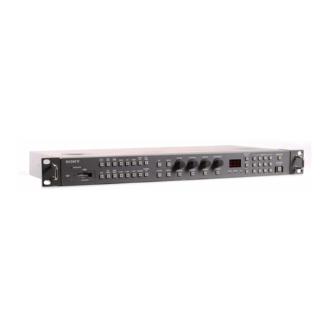
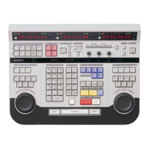
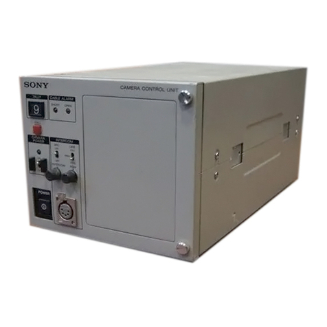
Sony PVE-500 User manual

3-757-576-12(1)
Model:
PVE-500
Operating
Instructions
page
1(€)
Before
operating
this
unit,
please
read
this
manual
thoroughly
and
retain
it
for
future
reference.
5
s
Mode
d
emploi
page
1(F)
Avant
la
mise
en
service
de
cet
appareil,
priére
de
lire
attentivement
ce
mode
d’emploi
que
I’on
conservera
pour
toute
référence
ultérieure.
Bedienungsanleitung
page
1)
Lesen
Sie
diese
Anleitung
bitte
sorgfaltig
durch
und
bewahren
Sie
sie
fur
spateres
Nachschlagen
auf.
©1993
by
Sony
Corporation

To
prevent
fire
or
shock
hazard,
do
not
expose
the
unit
to
rain
or
moisture.
CAUTION
RISK
OF
ELECTRIC
SHOCK
DO
NOT
OPEN
CAUTION:
TO
REDUCE
THE
RISK
OF
ELECTRIC
SHOCK,
OO
NOT
REMOVE
COVER
(OR
BACK).
NO
USER-SERVICEABLE
PARTS
INSIDE.
REFER
SERVICING
TO
QUALIFIED
SERVICE
PERSONNEL.
This
symbol
is
intended
to
alert
the
user
to
the
presence
of
uninsulated
“dangerous
voltage”
within
the
product’s
enclosure
that
may
be
of
sufficient
magnitude
to
constitute
a
risk
of
electric
shock
to
persons.
This
symbol
is
intended
to
alert
the
user
to
the
presence
of
important
operating
and
maintenance
(servicing)
instructions
in
the
literature
accompanying
the
appliance.
For
customers
in
the
U.S.A.
WARNING
This
equipment
has
been
tested
and
found
to
comply
with
the
limits
for
a
Class
A
digital
device,
pursuant
to
Part
15
of
the
FCC
Rules.
These
limits
are
designed
to
provide
reasonable
protection
against
harmful
interference
when
the
equipment
is
operated
in
a
commercial
environment.
This
equipment
generates,
uses,
and
can
radiate
radio
frequency
energy
and,
if
not
installed
and
used
in
accordance
with
the
instruction
manual,
may
cause
harmful
interference
to
radio
communications.
Operation
of
this
equipment
in
a
residential
area
is
likely
to
cause
harmful
interference
in
which
case
the
user
will
be
required
to
correct
the
interference
at
his
own
expense.
You
are
cautioned
that
any
changes
or
modifications
not
expressly
approved
in
this
manual
could
void
your
authority
to
operate
this
equipment.
The
shielded
interface
cable
recommended
in
this
manual
must
be
used
with
this
equipment
in
order
to
comply
with
the
limits
for
a
digital
device
pursuant
to
Subpart
B
of
Part
15
of
FCC
rules.
For
customers
in
Canada
This
apparatus
complies
with
the
Class
A
limits
for
radio
noise
emissions
set
out
in
Radio
Interference
Regulations.
Pour
les
utilisateurs
au
Canada
Cet
appareil
est
conforme
aux
normes
Classe
A
pour
bruits
radioélectriques,
spécifiés
dans
le
Reglement
sur
le
brouillage
radioélectrique.
Bescheinigung
des
Herstellers
Hiermit
wird
bescheinigt,
daf3
die
Schnitt-Steuereinheit
PVE-500
in
Ubereinstimmung
mit
den
Bestimmungen
der
BMPT-Amisblatt
Vig
243/1991
und
Vfg
46/1992
funkenst6rt
ist.
Der
vorschriftsmaBige
Betrieb
mancher
Gerate
(z.B.
MeBsender)
kann
allerdings
gewissen
Einschrankungen
unterliegen.
Beachten
Sie
deshalb
die
Hinweise
in
der
Bedienungsanleitung.
Dem
Bundesamt
fir
Zulassungen
in
der
Telekommunikation
wurde
das
inverkehrbringen
dieses
Gerates
angezeigt
und
die
Berechtigung
zur
Uberpriifung
der
Serie
auf
Einhaltung
der
Bestimmungen
eingeraumt.
Sony
Deutschland
GmbH
Hugo
Eckener
Str.
20
50829
Kdin
Hinweis
GemaB
der
Amtsblatter
des
BMPT
Nm.
61/1991
und
6/
1992
wird
der
Betreiber
darauf
aufmerksam
gemacht,
daB
die
von
ihm
mit
diesem
Gerat
zusammengestelite
Anlage
auch
den
technischen
Bestimmungen
dieser
Amtsblatter
genigen
muB.

Contents
Chapter
Tee
Outline
Chapter
2
eee
-Namesand
>
Functions
of
Parts.
Chapter
$62
Preparations
—
Chapter
4
_
Basic
Editing
—
Cut
Edits
Chapter
5
Editing
with
Two
Players
—
A/B
Roll
Edits
—
Chapter6
Advanced
Editing
|
About
this
Manwal
..........sscscsccsssssosseceosscescccesssssssescerscesacsscssssessenssensesces
3
(E)
Principal
Feature
.........cscccssccssscssssssccssccesccscccsssenscoscsseccessessresensorscczes
1-2
(E)
Optional
ACCESSOTIES
..........sscsscesesessecssccescessssccssscsscsecessacscsscessecsccccsese
1-4
(E)
Control
Panel
iiisescdiccecssessccesesssscecedcaedissedsveiscsassotedcessacteanceicctosesicadadeuse
2-2
(E)
Comme
ctOr
Panel
:.scccssccsesiesessessocacecsousssocsseosscssecssescedscscsaisassansventecedeivs
2-13
(E)
PROCAUTIONS
Sicescscesicesteceesicestencevecesscuscsabeaccsvecseucsoseicsdscecdésicdesdecebucedéeeies
3-2
(E)
CONNECEIONS
saves
cisisceccecssscscesvsacdoascsocsesssessiervesSooscacceséacscdveeseesecioaseddecsss
3-3
(E)
Preparations
for
Editing
...........cssscecsssssscsssssrscesssscscsecssssesssessncessrsers
3-7
(E)
PVE-500
Setup
(Initialization)
0.0.0.0...
cccccceccsccssesesececsesseanseeasees
3-8
(E)
Measuring
Start
Delays
.........c:cccccscsscscscsscsssessesessscesseaeeenaeeesees
3-14
(E)
Preparing
Tapes
for
Editing
.........ccccccessscsesesscescessssceseceeesenes
3-15
(E)
Standard
Editing
Session..........ssssssscscssccssecsesesssssccsscesssssssssascoeseeses
4-2
(E)
Selecting
the
Edit
Mode
..............cscsscssssscesscssssssssesesesoscssscsssesececsesoes
4-3
(EF)
Selecting
the
Player
vasesssciiesscsancsnenesusaandhedcasisctanvaiedsnossipassoassaesseseeseeses
4-5
(E)
Setting
Edit
Points
.........ssscsscccsscscscsssssssssceccensocsessecscsceasoacenessocesoeeses
4-6
(E)
Confirming
and
Adjusting
Edit
Points..............scccccssssscsssssssssesssonees
4-9
(E)
Previewing
the
Edit
............cccccscsscssssssssscsscssssesscssctsccescscssorsosscssesccens
4-11
(E)
Executing
the
Edit
.....sccccscccecscsscssersssasssscessencacsssessessescesecccsessansccdscess
4-12
(E)
Reviewing
the
Edit
...........scsscsssscescsscscsscsccesssssssssssecsscsesssensssesccsesoes
4-13
(E)
CUEDIME
:s
Siesiecassesccicadiscdissedesdovesssabasoncashesoocostececeaesioeseidedsccescelosscessssasescées
5-2
(E)
Selecting
FROM
and
TO
Sources.............scssssssssssscssssesssscssccssscessoeses
5-4
(E)
Setting
Edit
Points
............cccccssscssssssssssssssccssssescecrsoscsssssesessessenesseccoss
5-6
(E)
Setting
a
Transition
Time
..............cccsccssscssscsscossecssesssssccscsscssescccssenses
5-7
(E)
Controlling
the
DFS-500
Snapshot
Function.
.............scccccsssssosssossees
6-2
(E)
Controlling
the
DFS-500
During
an
A-Roll
Edit
..............cccceoee
6-2(2)
(E)
Previewing
Immediately
After
Setting
IN
Points
Qi
Ch:
Hing
oc
ctsccscncasscscssbeovssssossescetascessonacecsssdssscacssscosscaccsss
6-3
(E)
Resuming
Edit
After
Setting
Player
IN
Point
—
Butt
Editing
......
6-4
(E)
Using
Auxiliary
SOurces
..........csscssssssssccsecssscssssscstcsccsccsceseessssseceerarses
6-5
(E)
Setting
Separate
Audio
and
Video
IN
Points
—
Split
Editing
.......
6-7
(E)
Editing
Still
and
Variable-Speed
Playback
—
DT
Editing
............
6-9
(E)
Setting
Transition
Points
During
Preview
or
Edits
—
SYNC
Roll
Editing
«0.0...
esccssccscsssessesccossesssscescssscsoesees
6-12
(E)
Controlling
External
Equipment
via
the
GPI
Interface................
6-13
(E)
Meantial
PQitiing
ccccisccsisessccsvesscesecssssasccdeseonsiaconcassacecesedsoosesonccveueieedesese
6-14
(E)
Contents
|
-§
(E)

2
(E)
Contents
a
ga
ET
a
eh
CVAD
TIRE
seeceen
seed
cte
seas
eshense
decked
eieaieaand
cath
eta
eee
atentan
te
LD
Registering
an
Edit
(Internal
EDL
Mode
Onlly).......ssssssssscsesseesssseee
175
(KE)
Recalling
an
Edit
(Internal
EDL
Mode
Only)
.........ssssssssesssesseeeeeeee
7-6
(E)
Adjusting
and
Deleting
Edits
..........sssssssssssssssesssssecssessssesneessensesssseeee
7°7
(E)
Uploading/Downloading
the
EDL
(Internal
EDL
Mode
Only)......7-8
(E)
Error
Messages
.-sessscrssssssessessessescassessnssossessussosssesssssessescoccescessvenssessnees
AZ
(E)
Unt.
Case
Of
Trobe
sxiissveciessescsenvsscsss
sovsisisevavssconsodatessspavedessansivaveserseriew
eS
CE)
Specifications
..........ccrseessees
sobeeckeLedvededuseussavecsadsansidcsdeiicsssosscsssavecveansee
A=
(ED)
Optional
ACCESSOLES
....:.ic...sscsveiasossesaveseasesoncaisctingeatsereenesdesiesenes
A-5
(E)
Recommended
Equipment
0.0.0...
cccsscsscssseseessesesseceeeeseeeeeteerees
A-5
(E)
CIOS
SAN
V
scisssaviasisivsscusavasoncessiennnccecisvedhqanachabensoseensuausoapbsajeavinsastosansevens
NAO
(E)
THES
Saceeccdiedsiokcasintsnctesecwdock
Aden
it
e
del
LAE)
Contents

About
this
Manual
Intended
audience
This
section
describes
the
organization
of
this
manual
and
some
conventions
of
notation
used.
This
manual
is
a
guide
to
the
PVE-500
editing
control
unit.
It
is
intended
to
be
read
by
persons
responsible
for
the
operation
of
professional
video
equipment,
for
example,
at
cable
television
stations
and
corporate
production
facilities.
Therefore
it
assumes
that
readers
will
be
familiar
with
the
basic
concepts
of
video
editing
and
have
some
experience
in
operating
professional
video
equipment.
About
this
Manual
Manual
organization
The
organization
of
this
manual
is
as
follows.
Chapter
1
Outline
Explains
the
principal
features
of
the
unit
and
optional
accessories.
Chapter
2
Names
and
Functions
of
Parts
Briefly
explains
the
function
of
each
of
the
switches,
Sones
and
connectors
on
the
control
and
connector
panels.
Persons
already
familiar
with
professional
or
broadcast
editing
equipment
can
obtain
a
general
grasp
of
the
unit’s
capabilities
by
reading
through
this
chapter.
Chapter
3
Preparations
Covers
matters
which
you
need
to
know
before
using
the
unit,
such
as
how
to
connect
external
equipment
to
this
unit
in
order
to
configure
a
complete
editing
system,
and
preparations
to
make
before
starting
to
edit.
Chapter
4
Basic
Editing
—
Cut
Edits
Explains
how
to
perform
basic
cut
edits,
using
one
player
and
one
recorder,
for
instantaneous
switching
between
program
sources.
Chapter
5
Editing
with
Two
Players
—
A/B
Roll
Edits
Explains
how
to
perform
A/B
roll
edits
in
which
you
can
add
special
effects
while
switching
between
the
playback
signals
of
two
players,
using
a
video
switcher
and
an
audio
mixer
connected
to
this
unit.
Chapter
6
Advanced
Editing
Explains
advanced
techniques
not
covered
in
previous
chapters.
Chapter
7
Managing
Edit
Data
—
The
Edit
Decision
List
(EDL)
Explains
how
to
save
settings
made
in
order
to
execute
an
automatic
edit,
and
how
to
recall
the
settings
and
use
them
again.
About
this
Manual
£3
(E)
WU

nvout
ie
manuat
TI
TTETTTETT|
4
(E)
About
this
Manual
[gaa
Re
Appendix
Contains
a
list
of
error
messages
with
instructions
on
how
to
respond,
a
list
of
steps
to
take
when
you
suspect
trouble
with
the
unit,
specifications,
and
a
glossary
of
technical
terms
used
in
this
manual.
Conventions
About
this
Manual
Button
names
As
shown
in
the
example
below,
some
of
the
buttons
on
this
unit
have
two
functions,
depending
on
whether
they
are
pressed
alone
or
in
combination
with
the
ENTRY
button.
The
two
functions
are
indicated
on
the
top
and
front
sides
of
the
button.
SEE
Indicator
(LED)
LS?
Z\
PLAY
button
When
pressed
alone,
this
button
functions
as
the
PLAY
button.
This
manual
refers
to
it
simply
as
the
PLAY
button.
STOP
(ENTRY
+
PLAY)
button
When
pressed
together
with
the
ENTRY
button,
this
button
functions
as
the
STOP
button.
This
manual
refers
to
it
as
the
STOP
(ENTRY
+
PLAY)
button,
with
the
keys
to
press
indicated
in
parentheses.
Control
panel
illustrations
The
numbers
of
buttons
and
switches
in
illustrations
of
the
control
panel
correspond
to
steps
in
the
procedure
under
discussion.
In
order
to
keep
the
illustrations
simple,
frequently
used
buttons
are
sometimes
mentioned
in
the
text
but
not
numbered
in
the
illustrations.
Cross
references
References
to
other
manuals
or
to
sections
of
this
manual
containing
related
information
appear
in
italics.
Technical
terms
Technical
terms
are
explained
in
a
glossary
in
the
Appendix
to
this
manual.

Chapter
1
Outline
This
chapter
explains
the
principal
features
of
the
unit
and
optional
accessories.
Principal
Features
..isccociscsessnctcsscecesepssssencserssacsursensetastsncss
1-2
(E)
Optional
Accessories
...........sssccsscsesssccrsssscessecssessossessoenes
1-4
(E)

onapter
+]
TLLTTTTT
1-2
(E)
Principal
Features
Chapter
1
Outline
The
PVE-500
is
an
electronic
editing
control
unit
which
allows
you
to
perform
advanced
editing
easily
and
efficiently.
You
can
connect
a
video
switcher,
an
audio
mixer,
and
up
to
three
VTRs
to
configure
an
A/B
roll
editing
system.
The
principal
features
of
the
unit
are
as
follows.
Controls
up
to
three
VTRs
You
can
control
two
players
and
one
recorder
by
remote
control
from
the
control
panel
of
this
unit.
The
control
panel
features
independent
search
dials
and
control
buttons
for
the
players
and
the
recorder,
allowing
you
to
locate
edit
points
quickly
and
precisely.
Three
time
counters
There
are
three
time
counters,
allowing
you
to
view
time
count
data
for
two
players
and
one
recorder
simultaneously.
Video
switcher
control
You
can
connect
video
switchers
equipped
with
a
9-pin
serial
interface,
such
as
DFS-500
series
or
BVS-3000
series
video
switchers,
using
the
optional
9-pin
remote
cable.
Remote
control
of
the
video
switcher
allows
you
to:
*
execute
automatic
transitions
for
special
effects
when
switching
between
the
playback
of
selected
players.
*
control
the
DFS-500
snapshot
function,
for
automatic
storing
and
recalling
of
snapshots
in
coordination
with
edits
stored
in
this
unit.
Audio
mixer
contro!
You
can
connect
a
VSP-A600,
MXP-290,
or
MXP-390
series
audio
mixer,
or
another
audio
mixer
equipped
with
a
15-pin
parallel
or
9-pin
serial
interface,
using
the
optional
mixer
control
cable
or
a
9-pin
remote
cable.
Remote
control
of
the
audio
mixer
allows
you
to
switch
the
audio
signals
of
selected
players
and
to
control
automatic
transition
effects.
A/B
roll
editing
You
can
create
A/B
roll
effects
such
as
wipes
and
dissolves.
The
A
and
B
signals
can
be
selected
from
a
total
of
five
sources,
including
two
players
and
three
auxiliary
input
sources.
SYNC
roll
editing
You
can
synchronize
two
player
VTRs
to
execute
effects
automatically
at
specified
edit
points.
Flexible
edit
modes
You
can
choose
between
assemble
mode,
for
simultaneous
editing
of
video
and
two
audio
channels,
or
insert
mode,
which
allows
you
to
edit
video
and
audio
separately
or
in
combination.
In
insert
mode,
you
can
specify
separate
IN
points
(edit
start
points)
for
audio
and
video
(split
editing).

aE
aa
GE
Dynamic
Tracking
(DT)")
for
variable-speed
editing
If
your
player
supports
dynamic
tracking,
you
can
edit
freeze
frame
or
variable
speed
playback.
GPI?)
output
You
can
output
trigger signals
to
control
external
equipment
when
you
execute
an
edit.
Edit
Decision
List
You
can
register
data
for
up
to
100
edits
in
an
edit
decision
list
(EDL)
stored
in
the
unit’s
internal
memory
(internal
EDL
mode).
Internal
EDL
data
can
be
recalled
and
changed
at
any
time.
It
remains
in
the
unit’s
internal
memory
for
at
least
100
hours
after
the
power
is
turned
off
(provided
that
the
unit
has
been
powered
on
for
at
least
two
hours).
To
save
edit
data
permanently,
you
can
connect
a
personal
computer
or
other
external
I/O
device.
You
can
also
choose
to
output
edit
data
to
the
external
I/O
device
each
time
you
execute
an
automatic
edit
(external
EDL
mode).
TMi
Reference
video
signals
for
precise
synchronization
The
unit
can
use
reference
video
signals
for
precise
synchronization.
If
you
set
the
75-ohm
terminator
switch
to
OFF,
reference
video
signal
input
can
be
output
to
other
equipment
using
a
T
connector.
Start
delay
measurement
The
unit
automatically
measures
the
amount
of
time
which
a
connected
VTR
requires
to
achieve
stable
tape
movement
after
receiving
a
start
command.
Information
for
each
VTR
is
stored
in
the
unit’s
internal
memory.
It
remains
available
for
at
least
100
hours
after
the
unit
is
turned
off
(provided
that the
unit
has
been
powered
on
for
at
least
two
hours).
Easy
setup
and
initialization
Slide
switches
are
available
on
the
front
panel
for
easy
setting
and
selection
of
time
codes,
CTL
counts,
preroll*)
times,
and
synchronization
modes.
Less
frequently
used
settings
are
made
using
the
search
dials
and
a
setup
menu.
Error
messages
The
unit
alerts
you
to
mistaken
operations
with
a
warning
sound
and
a
concise
error
message.
Rack
mounting
With
the
RMM-500
control
panel
mount
adaptor,
you
can
mount
this
unit
in
a
standard
EJA*)
19-inch
rack
or
editing
operation
desk.
1)
DT
is
a
trademark
of
Sony
Corporation.
4)
EIA:
Electronic
Industries
Association
2)
GPI:
General
Purpose
Interface
3)
Preroll:
An
operation
in
which
a
VTR
begins
to
run
its
tape
from
a
point
a
few
seconds
in
advance
of
the
edit
IN
point,
enabling
the
tape
to
reach
a
steady
speed
at
the
edit
IN
point
and
to
synchronize
with
other
video
tapes.
Chapter
1
Outline
|
4-3
(E)

canter
{TTHTTHITHT|
1-4
(E)
(Oo)
trey
ar-1mACerer=1-t-10)
9
(<1)
Optional
accessories
such
as
the
following
are
available
for
purchase
for
use
with
this
unit.
RMN-500
control
panel
mount
adaptor
An
adaptor
which
allows
you
to
mount
the
unit
in
a
standard
EIA
19-inch
rack
or
editing
desk.
For
details
please
contact
a
Sony
sales
representative.
RMM-500
RMM-500
contro!
panel
mount
adaptor
RCC-5AA
mixer
control
cable
A
9-pin/15-pin
conversion
cable
for
use
in
connecting
an
audio
mixer
equipped
with
a
15-pin
parallel
interface
(VSP-A600,
MXP-290,
MXP-P390,
etc.)
to
this
unit.
RCC-5G/10G/30G
Cables
for
use
in
connecting
a
video
switcher
or
an
audio
mixer
equipped
with
a
9-
pin
serial
interface
(MXP-S390,
etc.)
to
this
unit.
Chapter
1
Outline

Chapter
2
Names
and
Functions
of
Parts
This
chapter
briefly
explains
the
function
of
each
of
the
switches,
controls,
and
connectors
on
the
control
and
connector
panels.
For
more
detailed
information
about
how
to
use
the
controls
to
set
up
and
operate
the
unit,
see
the
following
sections.
Control
Panel
ccscscccsccscccncvscsstsssscccecsossecovsssscnssvssectscsesaseses
2-2
(E)
Connector
Panel
..........cscccsccscosssccsscsscesssesssersscessccaceceses
2-13
(E)

canter
{I{||THT1
ITI
2-2
(E)
fOveyah
ine)
Mm
ar-l
als)
The
control
panel
is
configured
as
follows.
Detailed
information
for
each
of
the
controls
is
given
on
the
pages
indicated
in
parentheses.
Edit
number/transition/duration
Operation
mode
control
f
; :
:
section
(page
2-3(E))
setting
and
display
section
(page
2-6(E))
Player
1
time
counter
section
(page
2-4(E))
Recorder
time
counter
Player
2
time
counter
section
(page
2-5(E))
section
(page
2-5(E))
Edit
mode
setting
section
(page
2-7(E))
Source
selection
Powsn
ANS
COU
KL
AS
mE
ALE
ROL
Me
RON
FONT
AMOS
MORN
|
~ELITING
CONTROL
UNIT
PVE-S00
section
2-6(E,
.
nie
aaa
ssi
iaiaia
.
Vnte:
@
=
a
Bg
Pe
|
Bw
Manual
editing/setup
Power
switch
section
(page
2-8(E))
=
BM
2
Bim
A/B
roll
setting
section
(page
2-7(E))
Edit
point
setting
section
(page
2-10(E))
Automatic
editing
section
Recorder
operation
control
(page
2-12(E))
section
(page
2-10(E))
Player
operation
control
section
(page
2-9(E))
Control
panel
Chapter
2
Names
and
Functions
of
Parts

SS
my
gE
EE
ea
Operation
mode
control
section
@
LEARN
button
©
PREROLL
selector
3)
SYNCHRO
selector
©
Tc/RTCICTL
selector
Operation
mode
contro!
section
@
LEARN
button
Press
to
automatically
measure
the
start
delays
of
the
connected
VTRs.
©
PREROLL
(preroll
time)
selector
Set
the
preroll
time
to
7
(or
10)
seconds,
5
seconds,
or
3
seconds.
If
you
set
this
selector
to
7
seconds,
the
preroll
time
will
be
either
7
or
10
seconds,
depending
on
the
setting
made
using
the
setup
menu.
©
SYNCHRO
(synchronization)
selector
Determines
whether
or
not
to
synchronize
and
use
color
framing.
ON/CF:
Synchronizes
and
uses
color
framing.
This
yields
a
stable
picture,
but
editing
precision
is
slightly
lower.
ON:
Synchronizes
but
does
not
use
color
framing.
OFF:
Does
not
synchronize.
©
TC/RTC/CTL
(edit
reference)
selectors
(for
player
1,
player
2,
and
recorder)
Determine
the
time
counter
display
format
for
player
1
(P1),
player
2
(P2),
and
the
recorder
(R).
TC:
Displays
the
recorded
time
code
(absolute
value).
The
display
is
not
reset
even
if
you
press
the
RESET
button.
RTC:
Displays
an
incremented
or
decremented
time
code
after
reset
(relative
value).
Reset
when
you
press
the
RESET
button.
CTL:
Displays
a
CTL
pulse
count
after
reset.
‘Reset
when
you
press
the
RESET
button.
Chapter
2
Names
and
Functions
of
Parts
HIM
Chapter
2
2-3
(E)

cnaptoa||I|[]TTIIIf
2-4
(E)
Control
Panel
Player
1
time
counter
section
fp
ce
ee
@
RESET
button
@
SERVO
indicator
7)
IN
indicator
©
OUT
indicator
©
Time
counter
Player
1
time
counter
section
@
RESET
button
Press
to
reset
the
time
counter
©
and
to
reset
edit
points.
@
SERVO
indicator
(green)
Lights
when
player
1
is
running
with
the
servo
locked.
@
IN
(edit
start
point)
indicator
(red)
Lights
when
an
IN
point
has
been
set
for
player
1,
and
flashes
to
indicate
that
an
IN
point
needs
to
be
set.
Flashes
at
high
speed
while
an
IN
point
or
duration
(distance
from
an
IN
point
to
an
OUT
point)
is
being
displayed
in
the
time
counter
©.
©
OUT
(edit
end
point)
indicator
(red)
Lights
when
an
OUT
point
has
been
set
for
player
1,
and
flashes
to
indicate
that
an
OUT
point
needs
to
be
set.
Flashes
at
high
speed
while
an
OUT
point
or
duration
is
being
displayed
in
the
time
counter
©.
Chapter
2
Names
and
Functions
of
Parts
©
Time
counter
Depending
upon
the
setting
of
the
TC/RTC/CTL
selector,
displays
an
absolute
or
relative
time
code
for
player
1,
or
a
control
signal
count.
During
setup
with
the
setup
menu,
displays
the
menu
item
number.
Error
messages
are
also
displayed
in
this
time
counter.

Player
2
time
counter
section
—
Player
2
time
counter
section
During
setup
with
the
setup
menu,
the
time
counter
®
displays
an
abbreviated
item
title.
Recorder
time
counter
section
@®
RESET
button
@®
SERVO
indicator
®
IN
indicator
®
OUT
indicator
@®
Time
counter
HM
Other
buttons
and
indicators
have
the
sare
functions
as
those
explained
in
the
previous
section
“Player
1
time
counter
section.”
Chapter
2
B
RESET
button
@
SERVO
indicator
@
IN
indicator
®
OUT
indicator
=
®
Time
counter
20)
TOTAL
button
and
indicator
Recorder
time
counter
section
From
the
RESET
button
®
to
the
OUT
indicator
®,
these
buttons
and
indicators
have
same
functions
as
those
explained
under
items
©
to
©
in
“Player
1
time
counter
section”
(page
2-4(E)).
®
Time
counter
Depending
upon
the
settings
of
the
TC/RTC/CTL
selector
and
the
TOTAL
button
@,
displays
an
absolute
or
relative
time
code,
a
CTL
signal
count,
or
the
recorder’s
total
running
time.
During
setup
with
the
setup
menu,
displays
the
setup
item
data.
Error
messages
are
also
displayed
in
this
time
counter,
@
TOTAL
(tonal
running
time)
button
and
indicator
(red)
Press
the
TOTAL
button
if
you
want
to
display
the
recorder’s
total
running
time
in
the
time
counter.
The
indicator
begins
to
flash
when
you
press
the
button.
Press
the
button
again
to
restore
the
time
counter’s
original
display.
If
you
want
to
reset
the
total
running
time,
press
the
RESET
button
®
while
the
total
running
time
is
displayed
in
the
time
counter.
Chapter
2
Names
and
Functions
of
Parts
2-5
(E)

canta
|
{TT
HHTTIHI
Control
Panel
Edit
number/transition/duration
setting
and
display
section
a
€)
EDIT
NO/TRANS/DUR
buttons
@
EDIT
NO/TRANS/DUR
display
Edit
number/transition/duration
setting
and
display
section
€@
EDIT
NO./TRANS/DUR
(edit
number/
transition/duration)
buttons
Use
to
set
the
edit
number,
effect
transition
time,
or
the
duration
of
an
edit
segment.
The
three
buttons
correspond
to
the
three
digits
in
the
display
@.
®
EDIT
NO./TRANS/DUR
display
To
interpret
the
number
in
this
display,
check
the
TRANS
button
in
the
A/B
roll
setting
section.
If
the
TRANS
button
is
lit,
this
display
shows
an
effect
transition
time.
If
the
button
is
flashing,
the
display
shows
an
edit
duration.
If
the
button
is
out,
the
display
shows
the
current
edit
number.
Source
selection
section
@
P1/Aux1
(ENTRY
+
P1)
buttons
@)
p2/aux2
(ENTRY
+
P2)
button
@
FROM
TO/AUX3
(ENTRY
+
FROM
TO)
button
@
FROM
TO
indicators
Source
selection
section
@®
P1/AUX1
(ENTRY
+
P1)
button
P1
(player
1):
Press
to
select
the
VTR
connected
to
the
PLAYER
1
connector
as
the
source.
The
button
lights
when
you
press
it.
AUX!I1
(ENTRY
+
P1)(auxiliary
source
1):
Press
to
select
the
equipment
connected
to
the
AUX1
connector
as
the
source,
for
example,
a
camera
connected
to a
video
switcher.
@
P2/AUX2
(ENTRY
+
P2)
button
P2
(player
2):
Press
to
select
the
VTR
connected
tothe
PLAYER
2
connector
as
the
source.
The
button
lights
when
you
press
it.
AUX2
(ENTRY
+
P2)(auxiliary
source
2):
Press
to
select
the
equipment
connected
to
the
AUX2
connector
as
the
source,
for
example
a
camera
connected
to
a
video
switcher.
2-6
(E)
|
Chapter
2
Names
and
Functions
of
Parts
€
FROM
TO/AUX3
(ENTRY
+
FROM
TO)
button
FROM
TO:
Press
to
change
the
FROM
source
(source
before
a
transition)
or
the
TO
source
(source
after
a
transition).
AUX3
(ENTRY
+
FROM
TO)(auxiliary
source
3):
Press
to
select
the
equipment
connected
to
the
AUX3
connector
as
the
source,
for
example
a
camera
connected
to a
video
switcher.
@
FROM
TO
indicators
Green:
Indicate
whether
the
next
operation
willbe
for
the
FROM
source
or
the
TO
source.
Red:
Indicate
the
currently
selected
FROM
and
TO
sources.
Flash
when
the
selected
source
players
are
in
DT
playback
mode.

A/B
roll
setting
section
@
ase
SYNC
(ENTRY
+
A/B)
button
@
TRANS/DUR
(ENTRY
+
TRANS)
button
AJB
roll
setting
section
@
A/B/SYNC
(ENTRY
+
A/B)
button
A/B
(A/B
roll):
Press
to
select
A/B
roll
mode.
The
button
lights.
SYNC
(ENTRY
+
A/B)(SYNC
roll):
Press
to
select
SYNC
roll
mode.
The
button
begins
to
flash.
Edit
mode
setting
section
€)
ASMBL
button
30)
V
button
@®
TRANS/DUR
(ENTRY
+
TRANS)
button
TRANS
(transition):
Press
to
set
the
effect
transition
time.
The
button
lights.
DUR
(ENTRY
+
TRANS)
(duration):
Press
to
set
the
edit
duration.
The
button
begins
to
flash.
€@
Ai
button
&@
A2
button
Edit
mode
setting
section
@
ASMBL
(assemble)
button
Press
to
select
assemble
mode.
The
button
lights.
If
any
of
the
insert
mode
buttons
are
lit,
press
them
to
exit
insert
mode
before
pressing
this
button.
For
information
about
the
assemble
and
insert
modes,
see
“Selecting
the
Edit
Mode”
(page
4-3(E)).
®
V
(video)
button
Press
to
select
video
insert
mode.
The
button
lights.
If
the
ASMBL
button
is
lit,
press
it
to
exit
assemble
mode
before
pressing
this
button.
@
A1
(audio
1)
button
Press
to
select
channel
1
audio
insert
mode.
The
button
lights.
If
the
ASMBL
button
is
lit,
press
it
to
exit
assemble
mode
before
pressing
this
button.
@
A2
(audio.
2)
button
Press
to
select
channel
2
audio
insert
mode.
The
button
lights.
If
the
ASMBL
button
is
lit,
press
it
to
exit
assemble
mode
before
pressing
this
button.
Chapter
2
Names
and
Functions
of
Parts
HTM
Chapter
2
2-7
(E)

Control
Panel
SSS
a
aS
ee
Manual
editing/setup
section
cnaptor2
|]
TTT
TIT
€
REC/STORE
(ENTRY
+
REC)
button
@)
EDIT/SETUP
(ENTRY
+
EDIT)
button
Manual
editing/setup
section
@
REC/STORE
(ENTRY
+
REC)
button
REC
(record):
Press
to
put
the
unit
into
E-E
mode
!),
While
you
keep
the
button
pressed,
the
recorder’s
video,
audio
1
and
audio
2
input
signals
are
output
to
the
monitor
but
not
recorded.
For
manual
editing,
press
this
button
together
with
the
PLAY
button
@
in
the
recorder
operation
control
section
at
the
point
where
you
@
EDIT/SETUP
(ENTRY
+
EDIT)
button
EDIT:
Press
to
put
the
unit
into
E-E
mode,
using
the
edit
mode
set
with
the
edit
mode
buttons.
While
you
keep
the
button
pressed,
the
recorder’s
input
signals
selected
by
the
edit
mode
are
output
to
the
monitor
but
not
recorded.
For
manual
editing,
press
this
button
together
with
the
PLAY
button
@
in
the
recorder
operation
control
section
at
the
point
where
you
wish
to
begin
recording.
SETUP
(ENTRY
+
EDIT):
Press
to
call
up
the
search
dial
setup
menu
(setup
mode).
wish
to
begin
recording.
STORE
(ENTRY
+
REC):
If
the
unit
is
in
internal
EDL
mode
(see
page
7-3(E)),
edit
data
is
saved
in
the
unit’s
internal
memory.
If
this
button
is
pressed
while
you
are
using
the
setup
menu,
setup
data
for
the
current
menu
item
is
written
to
the
unit’s
EEPROM
2).
1)
E-E:
Electric-to-Electric
2)
EEPROM:
Electrically
erasable
programmable
ROM
2-8
(E)
|
Chapter
2
Names
and
Functions
of
Parts

Player
operation
control
section
€B
PLay/sTOP
(ENTRY
+
PLAY)
button
€
sTILL/STB
OFF
(ENTRY
+
STILL)
button
€D
REW/EVECT
(ENTRY
+
REW)
button
@
FF/vaR
(ENTRY
+
FF)
button
@®
Direction
indicators
®
Search
dial
Player
operation
control
section
@®
PLAY/STOP
(ENTRY
+
PLAY)
button
PLAY:
Plays
the
tape.
STOP
(ENTRY
+
PLAY):
Stops
the
tape.
€
STILL/STB
OFF
(ENTRY
+
STILL)
button
STILL:
Gives
a
still
picture.
STB
OFF
(ENTRY
+
STILL)(standby
off);
Press
when
the
unit
is
paused
or
displaying
a
still
picture
and
you
want
to
exit
standby
mode
(standby
off).
@
REW/EJECT
(ENTRY
+
REW)
button
REW
(rewind):
Rewinds
the
tape.
EJECT
(ENTRY
+
REW):
Ejects
the
cassette.
€
FF/VAR
(ENTRY
+
FF)
button
FF
(fast
forward):
Fast
forwards
the
tape.
VAR
(ENTRY
+
FF)(variable):
When
using
a
player
which
supports
Dynamic
Tracking
(DT),
press
the
search
dial
to
bring
it
to
the
raised
position,
then
press
this
button.
You
will
be
able
to
edit
noiseless,
variable-speed
playback
(DT
editing).
The
direction
indicator
®
flash
in
red
while
you
are
running
a
tape
in
variable-
speed
mode.
©
Direction
indicators
Light
to
show
the
tape
direction.
The
indicators
go
out
when
the
unit
is
in
standby
off
mode.
@®
Search
dial
Controls
the
movement
of
the
tape.
Use
while
searching
for
an
edit
point
or
during
DT
playback.
The
dial
has
two
positions:
a
raised
position
for
shuttle
mode
playback
and
a
depressed
position
for
jog
mode
playback.
Press
the
dial
to
move
from
one
mode
to
the
other.
If
your
player
supports
Dynamic
Tracking
(DT)
playback,
you
can use
this
dial
to
perform
noiseless
editing
of
variable-speed
playback.
With
the
search
dial
in
the
raised
position,
press
the
VAR
(ENTRY
+
FF)
button
©
to
enter
variable
playback
mode.
HIM
Chapter
2
Chapter
2
Names
and
Functions
of
Parts
|
2-9
(E)

cnagte2
||[/TTTHI
Control
Panel
Recorder
operation
control
section
@®
REWEJECT
@
PLAY/STOP
(ENTRY
+
REW)
button
(ENTRY
+
PLAY)
button
@
FFvaR
(ENTRY
+
FF)
button
@
sTILUSTB
OFF
(ENTRY
+
STILL)
button
©
Direction
indicators
®
Search
dial
=
Recorder
operation
control
section
These
controls
have
the
same
functions
as
those
(DT),
you
can
use
it
for
noiseless,
variable-speed
explained
in
“Player
operation
control
section”
(page
playback.
2-9(E)).
If
your
recorder
supports
Dynamic
Tracking
Edit
point
setting
section
@
@
/Fs
(ENTRY
+
[4]
)
button
@
Ges
(eEntrY+
©)
©)
LAST
EDIT/CLEAR
(ENTRY
+
LAST
EDIT)
button
@®
aupio
SPLIT/SPEED
(ENTRY+
AUDIO
SPLIT)
button
@
Recorder
IN
button
@)
Player
IN
button
@
Recorder
OUT
button
@
Player
OUT
button
@®
co
TO/RECALL
(ENTRY
+
GO
TO)
@
ENTRY
button
button
Edit
point
setting
section
@
]
/BS(ENTRY
+=]
)
button
together
with
both
the
IN
and
OUT
buttons.
[=]
(Trim
-):
Press
this
button
together
with
the
The
IN
and
OUT
points
will
be
moved
one
IN
button
@,
@
or
OUT
button
@,
@
when
you
frame
back.
want
to
move
an
IN
or
OUT
point
one
frame
BS
(ENTRY
+
[=])(previous
edit):
In
internal
back.
Keep
the
buttons
pressed
to
execute
this
EDL
mode,
calls
up
the
previous
edit.
Keep
function
continuously.
When
you
want
to
shift
this
button
pressed
to
execute
this
function
an
entire
edit
segment,
press
this
button
continuously.
2-10
(E)
Chapter
2
Names
and
Functions
of
Parts
Other manuals for PVE-500
1
Table of contents
Other Sony Control Unit manuals
Popular Control Unit manuals by other brands

Watts
Watts CIVIC1 Installation and operation manual

Albion
Albion ART 22 Flow Data and Installation Instructions

Feig Electronic
Feig Electronic OBID i-scan ID ISC.M02.M8-B installation manual

Honeywell
Honeywell Braukmann RV 284 installation instructions

Resol
Resol VA32 manual

BFT
BFT ELBA Installation and user manual