3
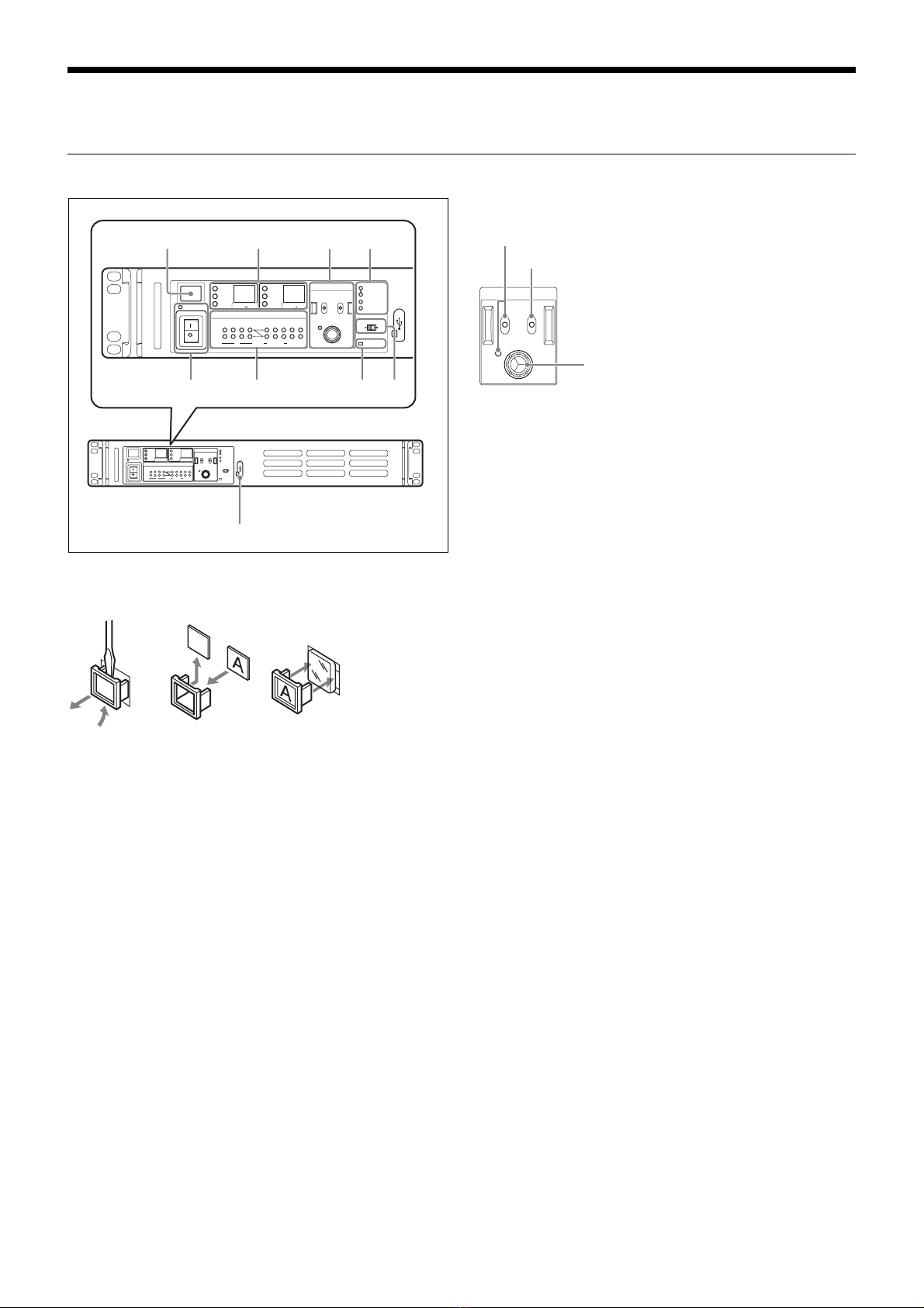
Overview
The HDRC-4000 HDR Production Converter Unit converts
HDR video signals using the OETF standard. OETF supports
several standards, including Sony’s original S-Log3 curve,
SMPTE ST 2084 (PQ) and ITU-R BT. 2100 (HLG), and
supports mutual conversion between standards.
The unit also features the AIR MATCHING (Artistic Intent
Render Matching) function, which allows you to convert to any
format, using HDR signal OETF mutual conversion, so that the
“look” is correct on a display that supports that particular OETF
standard format. When converting from SDR to HDR, a
conversion that results in an identical appearance is supported
using the Display Referred function.
In addition to HDR OETF conversion, it also supports
simultaneous mutual conversion between HDR/SDR, 4K/HD,
and 2020/709 color space for conversion of various signal
formats.
This unit also supports external reference sync signals, and
can be operated as a video signal frame synchronizer.
Features
Various video signal format conversion
support
Supports simultaneous conversion of various signal formats.
• HDRyHDR: OETF signal standard conversion
• HDRySDR: Dynamic range conversion
•4KyHD: Resolution conversion
• BT.2020yBT.709: Color space conversion
In addition, the SDI signal input/outputs also support the
following signal formats.
• 12G-SDI / 6G-SDI / 3G-SDI Level-A / 3G-SDI Level-B /
HD-SDI
• 2SI/SQD/No division
AIR MATCHING (Artistic Intent Render
Matching) function
This function performs OETF conversion of HDR signals that
maintains the image reproduction (visual appearance) on the
display.
When AIR MATCHING is ON, the conversion is performed
such that the image on a display connected to the input side
has the same visual appearance as the image on a display
connected to the output side. The OETF settings of these
displays are set as the input/output OETF.
When AIR MATCHING is OFF, conversion is performed
faithfully for the OETFs (Opto-Electronic Transfer Function)
configured for input/output. Whether the image reproduction
on the displays is the same or not is not taken into account.
Display Referred conversion
This function performs conversion of SDR signals to HDR
signals that maintains the image reproduction (visual
appearance) on the display.
When Display Referred conversion mode is ON, the input must
be SDR and the output is HDR. Also, the picture quality
adjustment settings (black level, inverse gamma conversion,
highlight creation), excluding the SDR-to-HDR conversion
gain, are fixed (OFF or 0.0).
Simultaneous output of 4K and HD signals
Simultaneously outputs 4K and HD signals as output video
derived from a single input signal.
The 4K output and HD output signal conversion settings can
be configured independently.
Dual system signal processing
Equipped with a dual system (channel A, channel B) signal
processing function.
A 4K signal or HD signal can be freely selected for each input
setting.
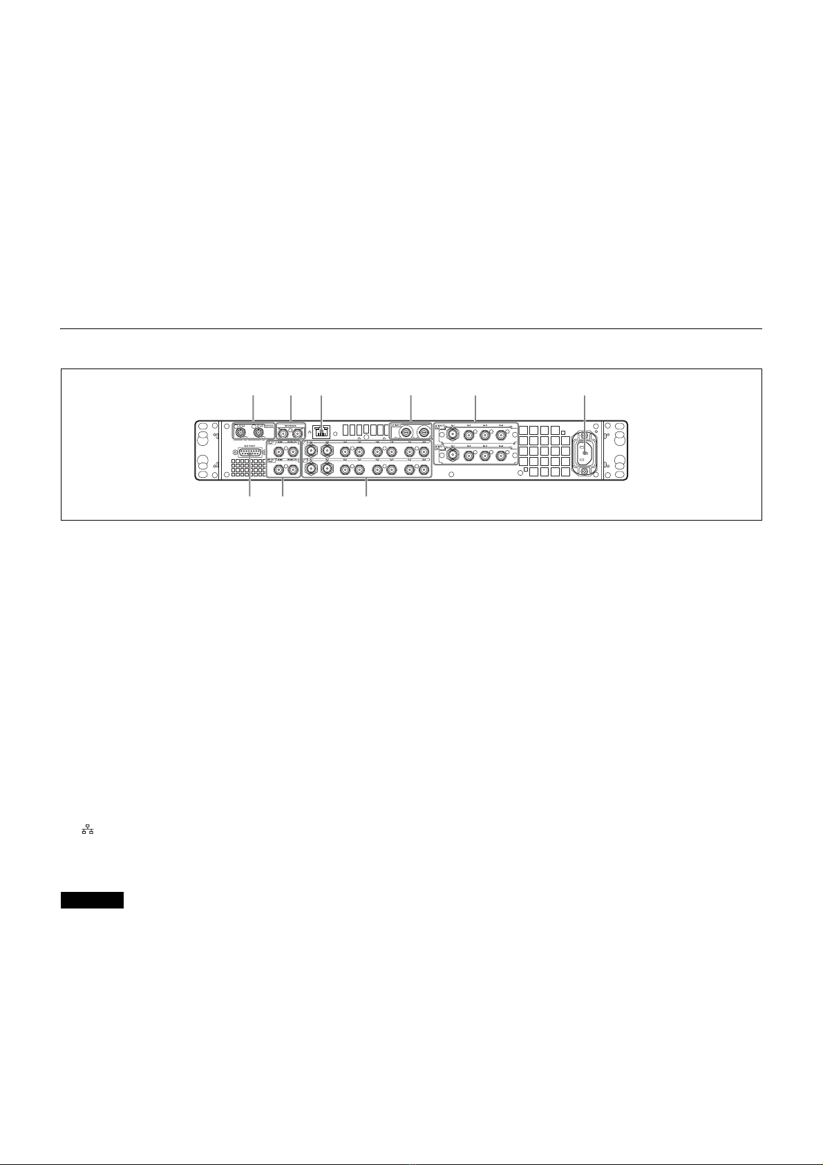
Video input/output
Inputs
Channel A
• 4K: 12G/6G-SDI × 1-ch, 3G-SDI × 2-ch, 3G/HD-SDI × 4-ch
or
HD × 4-ch: 3G/HD-SDI
• HD: 3G/HD-SDI
Channel B 1)
• 4K: 12G/6G-SDI × 1-ch, 3G-SDI × 2-ch, 3G/HD-SDI × 4-ch
or
HD × 4-ch: 3G/HD-SDI
• HD: 3G/HD-SDI
1) You can also select the channel A input signal as the channel B
input.
Outputs
Channel A
• 4K × dual system: 12G/6G-SDI × 1-ch, 3G/HD-SDI × 4-ch or
HD × dual system × 4-ch: 3G/HD-SDI
• HD × single system: 3G/HD-SDI
• HD monitor × single system: HD-SDI
Channel B
• 4K × dual system: 12G/6G-SDI × 1-ch, 3G/HD-SDI × 4-ch or
HD × dual system × 4-ch: 3G/HD-SDI
• HD × single system: 3G/HD-SDI
• HD monitor × single system: HD-SDI
External reference sync signal
The output signal can be synchronized to an external
reference sync signal (HD tri-level sync or SD sync). The
following sync signals are supported.
NTSC, PAL, 1080/59.94i, 1080/50i, 1080/23.98PsF, 1080/
24PsF
The unit is also equipped with a frame synchronizer function
allowing it to operate as a frame synchronizer.
If an external reference sync signal is not input, the output can
be synchronized to the channel A input signal. Operation
without an external reference sync signal, and input only on
channel B is not guaranteed.
Supported signal formats
4K: 2160/59.94P, 50P, 29.97P, 29.97PsF, 25P, 25PsF, 24P,
24PsF, 23.98P, 23.98PsF
HD: 1080/59.94P, 59.94i, 50P, 50i, 29.97PsF, 25PsF, 24PsF,
23.98PsF
(Input only) 720/59.94P, 50P
12G/6G-SDI input/output support
12G/6G-SDI Single-Link signals are supported for 4K signal
input/output.
3G/HD-SDI Multi-Link and 12G/6G-SDI Single-Link
conversion are supported using this function.