—10 —
9
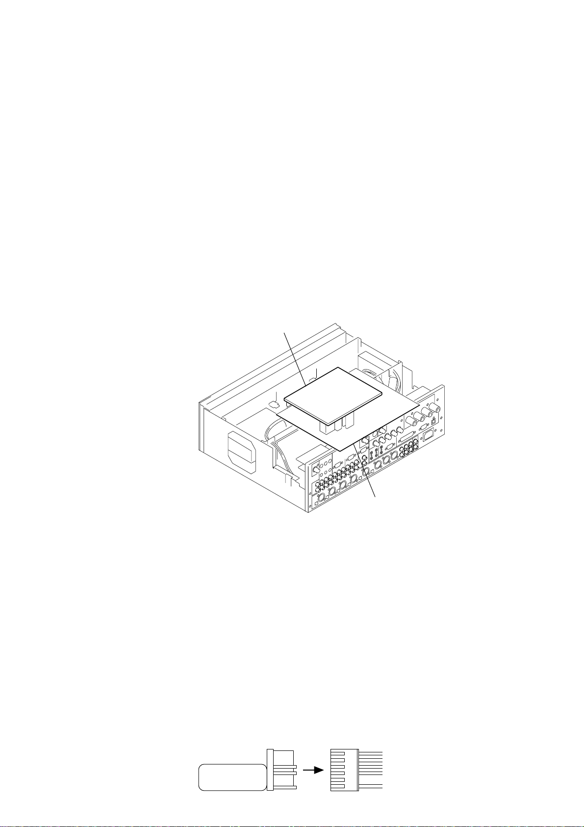
0映像出力端子
前面のLINE 4 SELECTボタンで選択された映像信号が出
力されます。映像信号方式は変換されません。
・5BNC出力端子
RGB信号とコンポーネント信号の出力端子です。
・VIDEO端子
コンポジット信号の出力端子です。
・S-VIDEO端子
Sビデオ信号の出力端子です。
qa CONTROL S OUTPUT 1〜4端子
LINE3 IN端子, LINE4 INPUT端子に接続されたAV機器
をリモートコントロールするための端子です。
ご注意
LINE3 IN端子に接続されたAV機器は、付属のソフトウェア
User Control Panelからは操作できません。
ソニー製DVD/VTR/CD/MD/オーディオ用CD-Rの再
生、停止、早送り、巻き戻し等の基本操作ができます。ま
た各端子ごとに接続方法をワイヤード接続かワイヤレス接
続かをSRP-X700P Managerにて選択します。
qs PROJECTOR CONTROL端子
映像出力端子に接続されたプロジェクターやプラズマディ
スプレイを制御する端子です。
工場出荷時はRS-232C接続でVPL-FX50を使用する設定
がされています。
・RS-232C端子
RS-232C端子を装備したプロジェクターやプラズマ
ディスプレイをRS-232Cで制御する端子です。
・CONTROL S IN/OUT端子
RS-232C端子をもたないプロジェクターをCONTROL
Sで制御する端子です。
CONTROL S OUT端子を使用し、プロジェクターを
操作する場合はコンポーネント信号とRGB信号の混在
使用はできません。
qd REMOTE PARALLEL端子
INPUT 12本、
OUTPUT 10本のパラレルリモート端子です。
INPUTは外部からの本機の制御、OUTPUTは本機からの
外部機器のリモートコントロールに使用します。各端子の
機能は付属のソフトウェア SRP-X700P Managerによ
り選択します。
qf REMOTE RS-232C端子
RS-232Cのリモート端子です。
外部のコントローラーなどを接続し、本機をリモートコン
トロールします。
qg REMOTE USB端子
付属のソフトウェア(SRP-X700P Manager、
User
Control Panel)をインストールしたコンピューターと接
続するための端子です。
ただし、前面のUSB端子を使用中は、前面のUSB端子が
優先されます。
qh ANT IN端子
ワイヤレスチューナー用のアンテナ入力端子です。
UHFアンテナはAN-820
(別売)を接続してください。
この端子はアンテナのブースター用電源9Vを出力してい
ます。上記以外のアンテナを接続するとうまく動作しな
かったり、故障の原因となることがあります。
ご注意
アンテナの設置・接続は、アンテナに付属の取扱説明書をよくお
読みのうえ、おこなってください。
アンテナの設置が不適当な場合、音声が途切れるなどの受信不良
の原因となることがあります。特にアンテナ取付後、取付場所の
変更が容易にできない場合は、事前に充分な動作確認をおこなっ
たうえで取り付けてください。
ケーブルにはインピーダンス50Ωの同軸ケーブルをお使いくださ
い。5D-FBで約50mまで配線できます。5C-2Vなど75Ω系のも
のは配線長が半減したり、トラブルの原因になることがありま
す。
雑音が発生するときは
設置場所によっては、外来雑音や妨害電波などの影響で雑音が発
生し、使用できないチャンネルが生じることがあります。
このような場合は、使用チャンネルを設定するときに、ワイヤレ
スマイクロホンやトランスミッターの電源をOFFにしたまま
チューナーユニットのチャンネルを切り換え、RF表示が点灯して
いないチャンネル(雑音や妨害電波の影響を受けていないチャンネ
ル)を選択して使用してください。ワイヤレスマイクロホンやトラ
ンスミッター側も、同じチャンネルに設定してください。
qj AC IN端子
付属の電源コードを接続します。
qk +48Vボタン
MIC INPUT1〜4端子にコンデンサマイクロホン用の
DC+48V電源を供給するボタンです。このボタンをON
($)にするとDC+48Vが出力されます。
工場出荷時はOFF
(4)に設定されています。
ql MIC/LINE切り換えボタン
MIC5/LINE1 IN, MIC6/LINE2 IN端子の入力レベルを
切り換えるボタンです。(P.19参照)
また、このボタンを(+48V)
MIC
($)にすると、
DC+48Vのコンデンサマイクロホン用の電源が自動的に
出力されます。
工場出荷時はLINE
(4)に設定されています。
ご注意
・+48VボタンとMIC/LINE切り換えボタンは誤操作防止のた
め、リアパネル面より押し込んだ状態がONになります。
・ケーブルを抜き挿しする場合や、+48Vボタン、MIC/LINE切
り換えボタンなどを切り換えるときは、必ずインプットフェー
ダーを全て絞るか、電源OFFの状態でおこなってください。
w; CIRCUIT BREAKER
本機の電源に過大な電流が流れた時、サーキットブレー
カーが作動し、電源を切ります。
サーキットブレーカーが作動したら、お買い上げ店または
添付の「ソニー業務用製品ご相談窓口のご案内」にあるお近
くのサービス窓口にご相談ください。
10
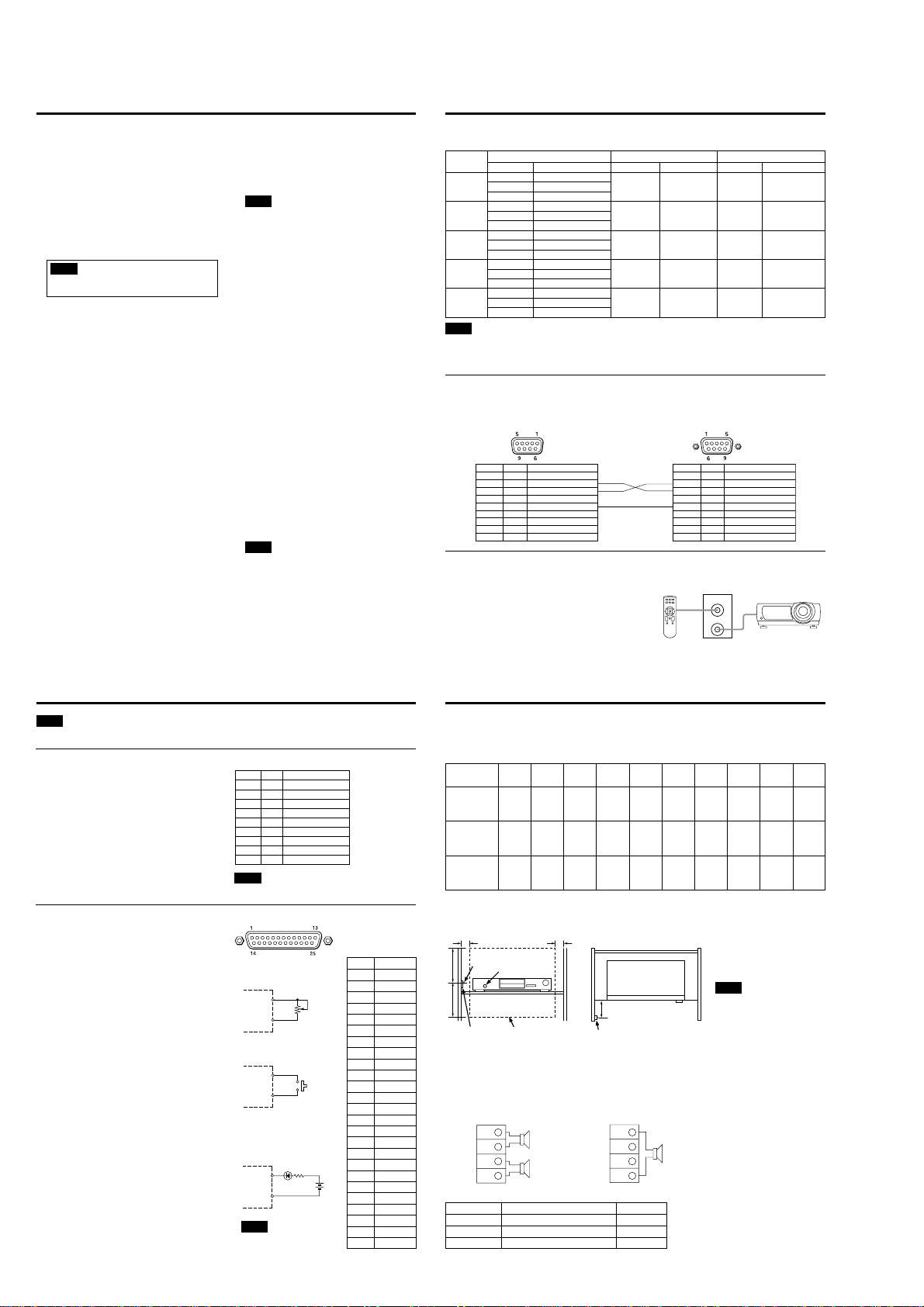
本機からディスプレイ機器を制御するには
本機に接続できるプロジェクターやディスプレイは下記のとおりです。
設定についてはコントロールソフトウェア・マニュアルの17ページ REMOTE画面の項をご覧ください。
ご注意
上記、対応機種以外についても対応できる場合があります。くわしくはお買い上げ店または、添付の「ソニー業務用製品ご相談窓口のご案内」
にある業務用製品ご購入相談窓口へお問い合わせください。上記の対応機種は、2002年4月1日現在のものです。
ご使用されるケーブル長は15m以下でお使いください。
PROJECTOR CONTROL CONTROL S IN/OUT端子
PROJECTOR CONTROL RS-232C端子
プロジェクターやプラズマディスプレイをRS-232C端子に接続するには
本機の動作に連動してプロジェクターやプラズマディスプレイの電源のON/STANDBYと入力信号切り換えをおこないます。
PFM-42B1
VPL-PX15
VPL-PX10
VPL-PS10
VPL-CX11
VPL-CX10
三洋電機(株)製
LP-XP45
LP-XP40
接続先コントロール
S
端子
———
———
CONTROL S/
PLUG IN POWER
端子
CONTROL S IN/
PLUG IN POWER
端子
———
X700P側
———
———
CONTROL S
PROJECTOR
OUT端子
CONTROL S
PROJECTOR
OUT端子
———
接続先リモート端子
RS-232C端子
REMOTE用端子
———
———
CONTROL PORT
端子
X700P側
PROJECTOR
CONTROL
(RS-232C)端子
PROJECTOR
CONTROL
(RS-232C)端子
———
———
PROJECTOR
CONTROL
(RS-232C)端子
接続先入力端子
INPUT A 5BNC端子
VIDEO IN S-VIDEO端子
VIDEO IN VIDEO端子
INPUT1 RGB/YUV端子
INPUT2 RGB/YUV端子
VIDEO COMPOSITE IN
端子
INPUT A端子
S-VIDEO端子
VIDEO端子
INPUT A端子
VIDEO IN S-VIDEO端子
VIDEO IN VIDEO端子
INPUT2 5BNC端子
INPUT3 S-VIDEO端子
INPUT3 VIDEO端子
X700P側
5BNC出力端子
S-VIDEO端子
VIDEO端子
5BNC出力端子
S-VIDEO端子
VIDEO端子
5BNC出力端子
S-VIDEO端子
VIDEO端子
5BNC出力端子
S-VIDEO端子
VIDEO端子
5BNC出力端子
S-VIDEO端子
VIDEO端子
機種名 映像端子 RS-232C 制御 CONTROL S 制御
<SRP-X700P側><
ソニー製プロジェクター/プラズマディスプレイ側>
(D-sub 9ピン、メス)(D-sub 9ピン、オス)
本機の動作に連動してプロジェクターの電源のON/STANDBYと
入力信号切り換えは、自動的におこなわれます。この場合、RGB
信号とコンポーネント信号の混在使用はできません。
また、CONTROL S IN端子にプロジェクター付属のワイヤード
リモコンを接続することで、本機を通してプロジェクターの設定
等をおこなうことができます。
電源供給の関係上、ステレオミニプラグ付きコードを製作してご使
用ください。ワイヤードリモコンを電池でお使いの場合は、ミニプ
ラグ付きコードをご使用ください。
<SRP-X700P>
CONTROL S プロジェクター
リモコン
PROJECTOR
IN
OUT
VPL-FX50
VPL-PX21
VPL-PX31
VPL-PX32
1FG フレーム接地
2RD 受信データ
3TD 送信データ
4ER データ端末レディ
5SG 信号線グランド
6DR データセットレディ
7RS 送信要求
8CS 送信可
9N.C 未接続
ピン番号 信号 機能
1FG フレーム接地
2 RX DA 受信データ
3 TX DA 送信データ
4 DTR データ端末レディ
5 GND接地
6 DSR データセットレディ
7RTS 送信要求
8 CTS 送信許可
9RI 被呼表示
ピン番号 信号 機能
11
本機を外部から制御するには
外部コントローラーから本機を制御するための端子です。
通信規約の仕様は次のようになります。
端子形状 :D-sub 9ピン、オス
電気的仕様 :RS-232C規格準拠
推奨ケーブル :データ通信用多芯シールドケーブル
ケーブル長 :15m以下
通信フォーマット
ボーレート :9600bps
ビット長 :8ビット
ストップビット :1ビット
パリティー :ODD
(奇数)
REMOTE RS-232C端子
外部に簡単な回路を接続することにより、リモートコント
ロールをおこなうための端子です。
INPUT端子
各端子の機能は付属ソフトSRP-X700P Managerの
REMOTE画面からPARALLEL INPUT FUNCTION設定
ボックスで設定します。
図のような可変抵抗器を接続することにより0〜−∞dBの範
囲で全てのフェーダーやボリュームのリモートコントロール
が可能です。
メイク接点により下記の操作が可能です。
・LINE4の入力選択
・ ミューティング
・ シーンリコール
・ 音量調整(Up/Down)
・CONTROL S端子に接続されているAV機器の制御
・ プロジェクターの電源ON/STANDBY
OUTPUT端子
各ピンのON条件は下記より選択できます。
・LINE4の入力セレクターの状態
・OVER、−∞インジケーターの点灯
・ シーンリコールボタンのON
・ プロジェクターの電源ON/STANDBY命令の発生
ON条件の選択は付属ソフトSRP-X700P Managerの
REMOTE画面からPARALLEL OUTPUT FUNCTION設
定ボックスで設定します。
REMOTE PARALLEL端子
<出力回路の例>
SRP-X700P
GND
(1, 14, 25番)
<入力回路の例>
入力端子
(2〜13番)
GND
(1, 14, 25番)
出力端子
(15〜24番)
LED
40mA MAX
←
24V
MAX
SRP-X700P
10kΩ
Bカーブ
可変抵抗器
SRP-X700P
ピン番号
1
2
3
4
5
6
7
8
9
10
11
12
13
14
15
16
17
18
19
20
21
22
23
24
25
機能
GND
INPUT1
INPUT2
INPUT3
INPUT4
INPUT5
INPUT6
INPUT7
INPUT8
INPUT9
INPUT10
INPUT11
INPUT12
GND
OUTPUT1
OUTPUT2
OUTPUT3
OUTPUT4
OUTPUT5
OUTPUT6
OUTPUT7
OUTPUT8
OUTPUT9
OUTPUT10
GND
(D-sub 25ピン、メス)
ご注意
コンピューターと接続するときにはクロスケーブルを用いてください。
0dB
–∞dB
ご注意
出力端子に逆電圧はかけないでく
ださい。
ご注意
USB端子はSRP-X700P ManagerとUser Control Panel から本機を制御するための専用端子です。
1FG
フレーム接地
2RD
受信データ
3TD
送信データ
4ER
データ端末レディ
5SG
信号線グランド
6DR
データセットレディ
7RS
送信要求
8CS
送信可
9 N.C
未接続
ピン番号 信号 機能
入力端子
(2〜13番)
GND
(1, 14, 25番)
12
本機からAV機器を制御するには
CONTROL S OUTPUT1〜4端子に接続しているソニー製機器の制御をおこなうことができます。操作可能なファンクション
は下表のとおりです。
ただし、付属のソフトウェアSRP-X700P ManagerおよびUser Control Panelでは誤操作防止のため、REC、
POWER ON、
POWER STANDBYをおこなうことができません。
コントロールS入力端子をもたないソニー製機器はAVマウス VM-50
(別売)を用いて制御します。
・制御したい機器のリモコン受光部位置を確認し、下図のようにAVマウスVM-50
(別売)を両面テープで固定します。
設置条件
・SRP-X700P ManagerまたはUser Control Panelを操作して、制御できることを確認します。
制御できないときは制御できる位置にAVマウスVM-50を移動してください。
スピーカーとの接続
本機へのスピーカー接続方法は動作モードによって異なります。
70V LINE時はモノラル出力になりますので、スピーカーの+端子をSPEAKERS CH-1の+端子(赤色)、スピーカーの−端子
をSPEAKERS CH-2の+端子(赤色)へ接続します。
・ローインピーダンス[Lo imp.]時 ・ハイインピーダンス[70V LINE]時
PREV. NEXT STOP REW. PLAY F.F. PAUSE REC POWER
POWER
ON
STANDBY
○○○○○○○○○○
——○○○○○○○○
○○○○○○○—○○
インピーダンス スピーカー1個あたりに加わる電力 接続可能個数
1kΩ5W 30
3.3kΩ1.5W 100
10kΩ0.5W 300
ハイインピーダンス[70V LINE]時に接続できるスピーカーの数は下表のとおりです。
MD
オーディオ用
CD-R
VTR1
(Beta)
VTR2
(8mm)
VTR3
(VHS)
VTR4
(DV)
CD
DVD
VM-50をラックの内側に設置し、発光部
から受光部を10cm程度後ろに下げ、上下
20cm以内で、左右5cm以上離れた位置
(図の点線部分)に機器の受光部が来るよう
に設置してください。
ご注意
発光部と機器の受光部の間に棚板等の遮
蔽物があると赤外線が遮られ、制御でき
なくなります。
※[]内の表記はSRP-X700P Managerで表示
されるものです。
CH-1
+
+
+
+
CH-1
–
–
–+
–
–
CH-2
CH-2
CH-1
+
+
CH-1
–
–
CH-2
CH-2
インピーダンス
4Ω〜16Ω
インピーダンス
32Ω〜10kΩ
5cm 5cm
発光部
20cm 20cm
正面から見た図 上面から見た図
機器のフロントパネル側
10cm
VM-50
VM-50
受光部
制御可能な範囲