Sony UP-D895 Guide

3-206-159-04 (1)
Digital Graphic
Printer
© 2001 Sony Corporation
UP-D895
ご使用になる前に ______________________________________ JP
Before Using this Printer _________________________________ GB
Avant d’utiliser cette imprimante ___________________________ FR
Vor Verwendung dieses Druckers __________________________ DE
Prima di usare la stampante ______________________________ IT
Antes de utilizar la impresora _____________________________ ES
Alvorens de printer te gebruiken ___________________________ NL
Innan du använder skri varen ______________________________ SE
Antes de usar a impressora _______________________________ PT
Ennen tulostimen kä yttöä ____________ _____________________ FI
Før printeren tages i brug ________________________________ DK
_______________________ GR
Før du bruker skr iveren __________________________________ NO
お買い上げいただきありがとうございます。
電気製品は安全のための注意事項を守らないと、
火災や人身事故になることがあります。
・本製品の取扱説明書は付属の CD-ROM に収録されています。
(対応 OS:Windows 95、Windows 98、Windows Me、Windows NT、Windows 2000)
・ 取扱説明書には、事故を防ぐための重要な注意事項と製品の取り扱いかたを示してありま
すので、取扱説明書をよくお読みのうえ、製品を安全にお使いください。お読みになった
あとは、いつでも見られるところに必ず保管してください。万が一、CD-ROM 内の情報
を紛失した場合、あるいは使用環境の状況により、CD-ROM を使用できない場合は、別
紙お問い合わせリストにある最寄りの販売会社までご連絡ください。

2
安全のために
本機は正しく使用すれば事故が起きないように、安全に
は充分配慮して設計されています。しかし、まちがった
使いかたをすると、火災や感電などにより死亡や大けが
など人身事故につながることがあり、危険です。
事故を防ぐために次のことを必ずお守りください。
安全のための注意事項を守る
3 ~ 4 ページの注意事項をよくお読みください。製品全
般の安全上の注意事項が記されています。
定期点検をする
長期間、安全にお使いいただくために、定期点検をする
ことをおすすめします。点検の内容や費用については、
お買い上げ店またはソニーの業務用ご相談窓口にご連絡
ください。
故障したら使わない
すぐに、お買い上げ店またはソニーの業務用ご相談窓口
にご連絡ください。
万一、異常が起きたら
m
a電源を切ります。
b電源コードや接続ケーブルを抜きます。
cお買い上げ店またはソニーの業務用ご相談窓口までご
相談ください。
・ 煙が出たら
・ 異常な音、においがしたら
・ 内部に水、異物が入ったら
・ 製品を落としたり、キャビネットを破損したと
きは
警告表示の意味
この取扱説明書および製品では、次のような表示
をしています。表示の内容をよく理解してから本
文をお読みください。
この表示の注意事項を守らないと、火災や感電な
どにより死亡や大けがなど人身事故につながるこ
とがあります。
この表示の注意事項を守らないと、感電やその他
の事故によりけがをしたり周辺の物品に損害を与
えたりすることがあります。
注意を促す記号
行為を禁止する記号
行為を指示する記号

3
下記の注意を守らないと、火災
や感電により死亡や大けがに
つながることがあります。
電源コードを傷つけない
電源コードを傷つけると、火災や感電の原
因となることがあります。
・ 設置時に、製品と壁やラック(棚)など
の間に、はさみこんだりしない。
・ 電源コードを加工したり、傷つけたりし
ない。
・ 重いものをのせたり、引っ張ったりしな
い。
・ 熱器具に近付けたり、加熱したりしない。
・ 電源コードを抜くときは、必ずプラグを
もって抜く。
万一、電源コードが傷んだら、お買い上げ
店またはソニーの業務用ご相談窓口に交換
をご依頼ください。
油煙、湯気、湿気、ほこりの多い場
所には設置しない
上記のような場所に設置すると、火災や感
電の原因となることがあります。
取扱説明書に記されている仕様条件以外の
環境での使用は、火災や感電の原因となる
ことがあります。
内部に水や異物を入れない
水や異物が入ると火災や感電の原因となる
ことがあります。
万一、水や異物が入ったときは、すぐに電
源を切り、電源コードや接続コードを抜い
て、お買い上げ店またはソニーの業務用ご
相談窓口にご相談ください。
内部を開けない
内部には電圧の高い部分があり、キャビ
ネットや裏蓋などを開けたり改造したりす
ると、火災や感電の原因となることがあり
ます。内部の調整や設定、点検、修理は、
お買い上げ店またはソニーの業務用ご相談
窓口にご依頼ください。
本機は国内用です
交流 100V でお使いください。
海外などで、異なる電圧で使うと、火災や
感電の原因となることがあります。
JP

4
下記の注意を守らないと、けが
をしたり周辺の物品に損害を与
えることがあります。
ぬれた手で電源プラグをさわらない
ぬれた手で電源プラグを抜き差しすると、
感電の原因となることがあります。
接続の際は電源を切る
電源コードや接続コードを接続するときは、
電源を切ってください。感電や故障の原因
となることがあります。
付属の電源コードを使う
付属の電源コードを使わないと、感電や故
障の原因となることがあります。
安全アースを接続する
安全アースを接続しないと、感電の原因と
なることがあります。
安全アースを取り付けることができない場
合は、お買い上げ店またはソニーの業務用
ご相談窓口にご相談ください。
不安定な場所に設置しない
ぐらついた台の上や傾いたところなどに設
置すると、倒れたり落ちたりしてけがの原
因となることがあります。
また、設置・取り付け場所の強度を充分に
お確かめください。
製品の上に乗らない、重いものを載
せない
倒れたり、落ちたり、壊れたりして、けが
の原因となることがあります。
カッターの刃には触れない
カッターの刃に触れると、けがをすること
があります。
本体内部に手を入れない
ドアが開いているときに、本体内部に手を
いれると、火傷および故障の原因となるこ
とがあります。
ドアの上に指を置かない
ドアを閉める際はドアの上に指を置かない
でください。
フロントパネルとの間に挟んでけがの原因
となることがあります。
お手入れの際は、電源を切って電源
プラグを抜く
電源を接続したままお手入れをすると、感
電の原因となることがあります。
移動させるときは電源コード、接続
コードを抜く
接続したまま移動させると、コードが傷つ
き、火災や感電の原因となることがありま
す。
通風孔をふさがない
通風孔をふさぐと内部に熱がこもり、火災
や故障の原因となることがあります。風通
しをよくするために次の項目をお守りくだ
さい。
・ 壁から 10cm 以上離して設置する。
・ 密閉された狭い場所に押し込めない。
・ 毛足の長い敷物 ( じゅうたんや布団など )
の上に設置しない。
・ 布などで包まない。
・ あお向けや横倒し、逆さまにしない。

5
使用上のご注意
使用上のご注意
電源について
・ 電源は AC100V をお使いください。
・ 3 芯- 2 芯 AC 変換アダプターを使う場合は、アース
端子を必ず接地してください。
・ 電源コードは傷つけないでください。
・ 長い間使わないときは、電源コードを抜いておいてくだ
さい。
・ 電源コードを抜くときは、電源プラグを持って抜いてく
ださい。
安全のために
・ キャビネットは絶対に開けないでください。内部に触れ
ると危険です。
・ 内部にものを落とさないでください。
・ ペーパーカッターには触れないでください。
置き場所について
・ 水平な場所に置いてください。傾けた状態で本機を使用
すると故障の原因になります。
・ 暑い所や湿気の多い所に置かないでください。
・ 湿気の低い冬場では、湿度 35% 以上の環境で使うこと
をおすすめします。
・ 結露にご注意ください。
温度の低い場所から暖かい場所に移動したり、暖房で湯
気や湿気がたち込めた部屋に置くと、本機の内部に水滴
がつくことがあります。これを結露といいます。この状
態で本機を使用すると、正常に動かないばかりでなく、
故障の原因になります。結露の可能性のあるときは、電
源を切り、しばらくそのまま放置してください。
持ち運びについて
・ ぶつけたり、落としたりしないように気をつけてください。
・ 持ち運びの際は、プリンター用紙を取り外してくださ
い。プリンター用紙を取り付けたまま持ち運ぶと故障の
原因になることがあります。
アースにつなぐ

6主な仕様
主な仕様
プリンター
感熱ヘッド 薄膜サーマルヘッド 1280 ドット
階調数 256 階調(8 ビット)
メモリー容量 4096 × 1280 × 8 (bit)
画面寸法 最大 320 × 100 mm
プリント速度 約 5.1 秒 /1 画面(1280 × 1280 ドッ
ト時)
画素数 最大 4096 × 1280 ドット
画素密度 H:100 mm/1280 ドット= 0.078
mm/ ドット
V:100 mm/1280 ドット= 0.078
mm/ ドット
正方ドット
電源 AC100V、50/60Hz
消費電力 20W(スタンバイ時)
120W(プリント時)
動作温度 5 ℃~ 35 ℃
動作湿度 20% ~ 80%
保管/輸送時温度
-20℃~60℃
保管/輸送時湿度
20% ~ 90%
最大外形寸法 154 × 105 × 260mm(幅 / 高さ / 奥
行き)
質量 3.4kg(本体のみ)
付属品 プリンター用紙(UPP-110HG)(1)
AC 電源コード (1)
3 芯- 2 芯 AC 変換アダプター (1)
ヘッドクリーニングシート (1)
プリンタードライバー / 取扱説明書ディ
スク (1)
ご使用になる前に (1)
サービス窓口のしおり・ご相談窓口のご
案内 (1)
保証書 (1)
ソフトウェア使用契約書 (1)
メディアラベル (1)
インターフェース
パラレルインターフェース
制御用端子 IEEE1284-B コネクター(D-sub 36
ピン)
入力:最大 5 V(TTL)
出力:最大 5 V(TTL)
データ転送方式 8 ビット、パラレル、IEEE STD 1284-
1994 準拠
・Compatible
・ Reverse Nibble
・ECP
ロジックレベル TTL
パラレルインターフェースコネクターのピ
ン配列
UP-D895 は、双方向パラレルインターフェース(IEEE
STD 1284-1994)規格のうち、Compatible モード、
Reverse Nibble モードおよび ECP モードに対応してい
ます。
H
V
Pin 番号 I/O 信号
インターフェースのモード
Compatible
Nibble ECP
1InStrobeHostClkHostClk
2I/O Data1(LSB)
3I/O Data2
4I/O Data3
5I/O Data4
6I/O Data5
7I/O Data6
8I/O Data7
9I/O Data8(MSB)
10 O nACK PtrClk PeriphClk
11 O Busy PtrBusy PeriphAck
12 O PError
AckDataReq
nAckReverse
13 O Select Xflag Xflag
14 I nAutoFd HostBusy HostAck
15 Not defined
16-17 GND
18 O
Periphral Logic High(1kΩ で +5V にプルアップ)
19-30 GND
31 I nInit nInit nReverseRequest
32 O nFault nDataAvail nPeriphRequest
33 Not defined
34 Not defined
35 Not defined
36 I nSelectln IEEE 1284
Active
IEEE 1284
Active

7
主な仕様
USB インターフェース
データ転送方式 Universal Serial Bus Specification
Revision 1.0 準拠
USB インターフェースコネクターのピン
配列
本機の仕様および外観は、改良のため予告なく変更する
ことがありますが、ご了承ください。
本機は「JIS C 61000-3-2 適合品」です。
Pin 番号 I/O 信号名 機能
VCC ケーブル電源、最大電流
100mA
I/O -Data データ
I/O +Data データ、1.5kΩ の抵抗を経由
して +3.3V にプルアップ
Ground ケーブルグランド
この装置は、情報処理装置等電波障害自主規制協議会(VCCI)
の基準に基づくクラス A 情報技術装置です。この装置を家庭環
境で使用すると電波妨害を引き起こすことがあります。この場
合には使用者が適切な対策を講ずるよう要求されることがあり
ます。

2
WARNING
To prevent fire or shock hazard, do not expose the unit to
rain or moisture.
To avoid electrical shock, do not open the cabinet. Refer
servicing to qualified personnel only.
THIS APPARATUS MUST BE EARTHED.
For the customers in the U.S.A.
This equipment has been tested and found to comply
with the limits for a Class A digital device, pursuant to
Part 15 of the FCC Rules. These limits are designed to
provide reasonable protection against harmful
interference when the equipment is operated in a
commercial environment. This equipment generates,
uses, and can radiate radio frequency energy and, if not
installed and used in accordance with the instruction
manual, may cause harmful interference to radio
communications. Operation of this equipment in a
residential area is likely to cause harmful interference in
which case the user will be required to correct the
interference at his own expense.
You are cautioned that any changes or modifications not
expressly approved in this manual could void your
authority to operate this equipment.
This device requires shielded interface cables to comply
with FCC emission limits.
For the customers in Canada
This unit has been certified according to Standard CSA
C22.2 NO.601.1.
Important safeguards/notices for use in
the medical environments
1 All the equipments connected to this unit shall be
certified according to Standard IEC60601-1,
IEC60950, IEC60065 or other IEC/ISO Standards
applicable to the equipments.
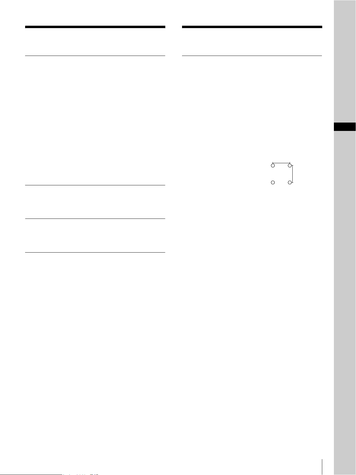
2 When this unit is used together with other equipment
in the patient area*, the equipment shall be either
powered by an isolation transformer or connected via
an additional protective earth terminal to system
ground unless it is certified according to Standard
IEC60601-1.
* Patient Area
3 The leakage current could increase when connected
to other equipment.
4 This equipment generates, uses, and can radiate
frequency energy. If it is not installed and used in
accordance with the instruction manual, it may cause
interference to other equipment. If this unit causes
interference (which can be determined by unplugging
the power cord from the unit), try these measures:
Relocate the unit with respect to the susceptible
equipment. Plug this unit and the susceptible
equipment into different branch circuit. Consult your
dealer. (According to Standard EN60601-1-2 and
CISPR11, Class B, Group 1)
Caution
When you dispose of the unit or accessories, you must
obey the law in the relative area or country and the
regulation in the relative hospital.
Warning on power connection
Use a proper power cord for your local power supply.
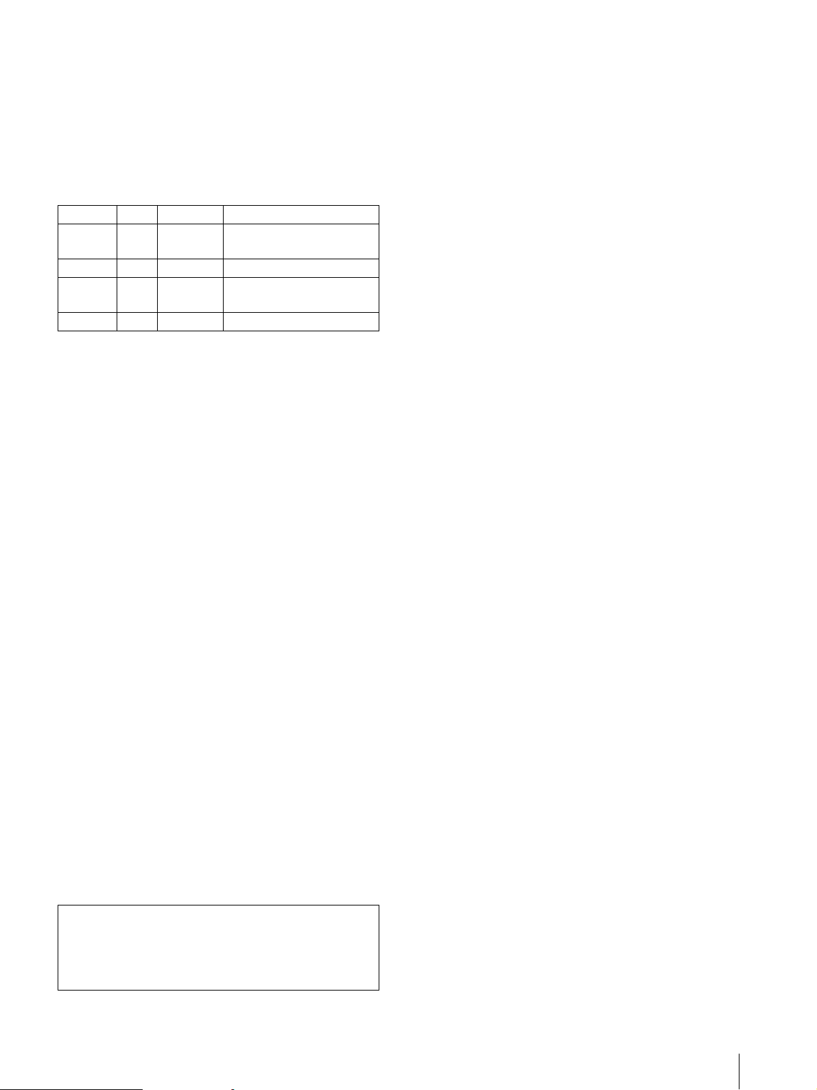
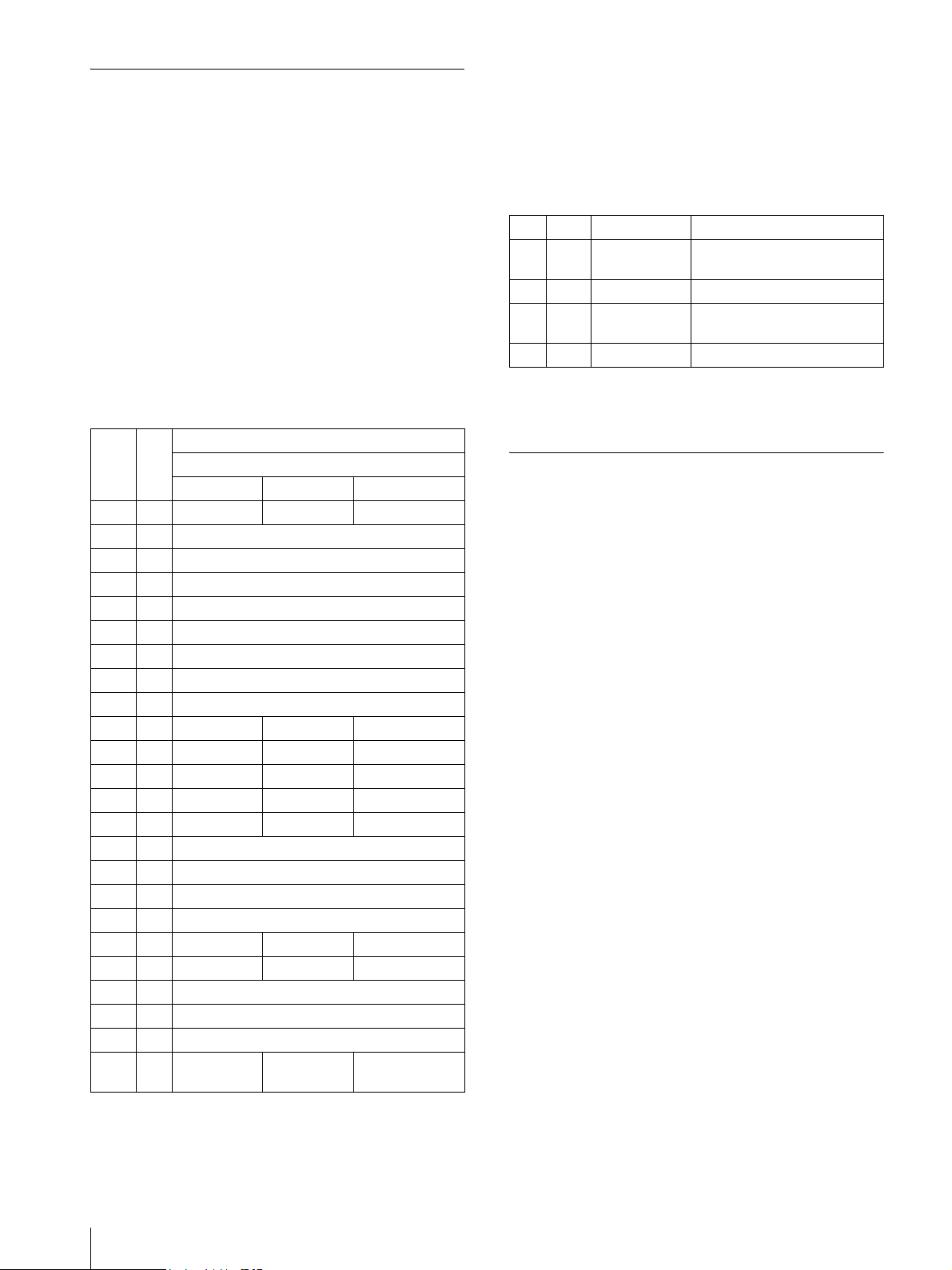
Warning on power connection for medical use
Please use the following power supply cord.
With connectors (plug or female) and cord types other
than those indicated in this table, use the power supply
cord that is approved for use in your area.
*Note: Grounding reliability can only be achieved when the equip-
ment is connected to an equivalent receptacle marked ‘Hospital Only’
or ‘Hospital Grade’.
Symbol on the products
This symbol indicates the equipotential
terminal which brings the various parts of
a system to the same potential.
This symbol is intended to alert the user to
the presence of important operating and
maintenance (servicing) instructions in
the literature accompanying the
appliance.
United States Canada
Plug type HOSPITAL GRADE* HOSPITAL GRADE*
Female end E62405, E35708 LR53182, LL022442,
LL088408
Cord type E159216, E35496
Min.Type SJT
Min.18 AWG
LL112007-1, LL20262,
LL32121, LL84494
Min.Type SJT
Min.18AWG
Minimum cord set
rating 10A/125V 10A/125V
Safety approval UL Listed CSA
R1.5m

Precautions / Specifications 3
Precautions
On safety
• Check the operating voltage before operation.
Operate the unit only with a power source specified in
“Specifications”.
• Stop operation immediately if any liquid or solid
object falls into the cabinet. Unplug the unit and have
it checked by qualified personnel.
• Unplug the unit from the wall outlet if you will not be
using it for a long time. Disconnect the power cord by
grasping the plug. Never pull the cord itself.
• Do not disassemble the cabinet. Refer servicing to
qualified personnel only.
• Do not touch the cutting blade of the printer.
• Connect the power plug of the printer to a wall outlet
with a protective earth terminal. The safety earth
should be properly established.
On operation
Do not turn the power off while the printer is printing.
The thermal head may be damaged.
On the printer carriage
Do not carry or move the printer when the paper roll is
placed in the printer. Doing so may cause a malfunction.
On installation
• Place the printer on a level and stable surface.
If you use the printer with placed on an uneven
surface, malfunction of the printer is likely to occur.
• Do not install the printer near heat sources. Avoid
locations near radiators or air ducts, or places subject
to direct sunlight or excessive dust, humidity,
mechanical shock or vibration.
• Provide adequate air circulation to prevent heat build-
up. Do not place the printer on surfaces such as rugs,
blankets, etc., or near materials such as curtains and
draperies.
• If the printer is subjected to wide and sudden changes
in temperature, such as when it is moved from a cold
room to a warm room or when it is left in a room with
a heater that tends to produce large amounts of
moisture, condensation may form inside the printer.
In such cases the printer will probably not work
properly, and may even develop a fault if you persist in
using it. If moisture or condensation forms, turn off
the power and allow the printer to stand for at least one
hour.
Specifications
Printer
Thermal head Thin-film thermal head, 1280 dots
Gradation 256-level gradation (8-bit)
Memory capacity
4096 ×1280 ×8 (bit)
Picture size 320 ×100 mm (max.)
Printing speed About 5.1 sec./image (1280 ×1280
dots)
Picture elements
4096 ×1280 dots (max.)
Dot density H: 100 mm/1280 dots = 0.078
V: 100 mm/1280 dots = 0.078
Square dots
Power supply 100 to 120V AC, 50/60Hz, 1.5A
220 to 240V AC, 50/60Hz, 0.8A
Temperatures Operating
5°C ~ 35°C (41°F ~ 176°F)
Storage/Transport
–20°C ~ 60°C (–4°F ~ 140°F)
Humidity Operating
20% ~ 80%
Storage/Transport
20% ~ 90%
Dimensions 154 ×105 ×260 mm (w ×h ×d)
6.1 ×4.1 ×10.2 in. (w ×h ×d)
Weight 3.4 kg (1.54 lb.) (printer only)
Accessories provided
Printer paper UPP-110HG ×1 roll
AC power cord ×1
Thermal head cleaning sheet ×1
Printer driver/Instructions for use
disc ×1
Before Using this Printer ×1
Service Contact List × 1
Software License ×1
Media label ×1
H
V
GB

Specifications
4
Interface
Parallel Interface
Control connector
IEEE1284-B Connector (D-sub 36-
pin)
Input: 5V (TTL) (max.)
Output: 5V (TTL) (max.)
Data transmission
8-bit, parallel, IEEE STD 1284-1994
Standard
Compatible, Reverse nibble, ECP
Logic level TTL
Parallel Interface Connector Pin
Assignment
UP-D895 is compatible with the Compatible, Reverse
Nibble, and ECP Modes with the bi-directional parallel
interface (IEEE STD 1284-1994).
USB Interface
Data transmission
Universal Serial Bus Specification Rev.
1.0 Standard
USB Interface Connector Pin Assignment
The design and these specifications are subject to
change without prior notification.
Medical Specifications
Protection against electric shock:
Class I
Protection against harmful ingress of water:
Ordinary
Degree of safety in the presence of flammable
anesthetics or oxygen:
Not suitable for use in the presence
of flammable anesthetics or oxygen
Mode of operation:Continuous
Pin I/O Signal
Interface Mode
Compatible Nibble ECP
1 I nStrobe HostClk HostClk
2 I/O Data1 (LSB)
3 I/O Data2
4 I/O Data3
5 I/O Data4
6 I/O Data5
7 I/O Data6
8 I/O Data7
9 I/O Data8 (MSB)
10 O nACK PtrClk PeriphClk
11 O Busy PtrBusy PeriphAck
12 O Perror AckDataReq nAckReverse
13 O Select Xflag Xflag
14 I nAutoFd HostBusy HostAck
15 Not defined
16-17 GND
18 O Peripheral Logic High (pull up to +5V at 1kΩ)
19-30 GND
31 I nInit nInit nReverseRequest
32 O nFault nDataAvail nPeriphRequest
33 Not defined
34 Not defined
35 Not defined
36 I nSelectIn IEEE 1284
Active IEEE 1284
Active
Pin I/O Signal Function
VCC Cable power, Max. current
100mA
I/O –Data Data
I/O +Data Data, pull up to +3.3V through
a 1.5kΩresistance
Ground Cable ground


2
AVERTISSEMENT
Pour prévenir tout risque d’incendie ou d’électrocution,
garder cet appareil à l’abri de la pluie et de l’humidité.
Pour prévenir tout risque d’électrocution, ne pas ouvrir
le boîtier. Confier l’entretien de cet appareil
exclusivement à un personnel qualifié.
CET APPAREIL DOIT ETRE RELIE A LA TERRE.
Pour les utilisateurs au Canada
Cet appareil a été homologué conformément à la norme
CSA C22.2 No.601.1.
Avertissement sur le connecteur d’alimentation
Utiliser un cordon d’alimentation approprié à votre
tension d’alimentation secteur locale.
Avertissement sur le connecteur d’alimentation
pour usage médical
Prière d’utiliser le code d’alimentation électrique
suivant.
Avec des connecteurs (fiche ou fiche femelle) et des
types de câbles différents de ceux indiqués dans ce
tableau, utiliser le câble d’alimentation électrique agréé
pour votre secteur.
*Remarque : La fiabilité de la mise à la terre n’est réalisable que si
l’équipement est branché sur une prise de courant équivalente
identifiée ‘Hôpital uniquement’ ou ‘Classe hôpital’.
Instructions de sécurité importantes en
vue d’une utilisation dans un
environnement médical
1 Tous les équipements raccordés à cet appareil doivent
être agréés suivant les normes IEC 60601-1,
IEC 60950, IEC 60065 ou les autres normes IEC/ISO
applicables à ces équipements.
2 Si cet appareil est utilisé conjointement avec d’autres
équipements à proximité d’un patient*, ces
équipements doivent être alimentés par un
transformateur d’isolement ou raccordés à la mise à la
terre du système par une borne de terre de protection
sauf s’ils sont agréés suivant la norme IEC 60601-1.
* Proximité d’un patient
3 Dans le cas d’une connexion à d’autres équipements,
le courant de fuite peut augmenter.
4 Cet appareil génère, utilise et peut émettre des
radiofréquences. S’il n’est pas installé et utilisé
conformément au mode d’emploi, il peut provoquer
des interférences avec d’autres appareils. Si cet
appareil génère des interférences (ce que l’on peut
facilement contrôler en débranchant le cordon
d’alimentation de l’appareil), appliquez l’une des
mesures suivantes : Installez cet appareil à un autre
endroit en tenant compte de l’autre équipement.
Branchez cet appareil et l’autre équipement sur des
circuits d’alimentation différents. Consultez votre
revendeur. (Suivant les normes EN60601-1-2 et
CISPR11, Classe B, Groupe 1)
Attention
Lorsque vous éliminez l’appareil ou ses accessoires,
vous devez vous conformer aux dispositions légales
applicables en la matière dans votre zone géographique
ou dans votre pays ainsi qu’au règlement de l’hôpital en
question.
Symbole
Ce symbole indique la borne
équipotentielle qui ramène les différentes
parties d’un système à la même tension.
Ce symbole est destiné à attirer l’attention
de l’utilisateur sur la présence
d’instructions d’utilisation et de
maintenance (réparation) importantes
dans la documemtation accompagnant
l’appareil.
Etats-Unis Canada
Type de fiche CLASSE HOPITAL* CLASSE HOPITAL*
Fiche femelle E62405, E35708 LR53182, LL022442,
LL088408
Type de câble E159216, E35496
Min.Type SJT
Min.18 AWG
LL112007-1, LL20262,
LL32121, LL84494
Min.Type SJT
Min.18AWG
Intensité nominale
du câble minimale 10A/125V 10A/125V
Agréation de
sécurité UL Listed CSA
R1.5m

Précautions 3
Précautions
Sécurité
• Vérifiez la tension secteur avant toute utilisation.
Faites uniquement fonctionner l’appareil avec l’une
des sources d’alimentation spécifiées dans les
“Spécifications”.
• Interrompez immédiatement le fonctionnement de
l’imprimante si un liquide ou un solide tombe à
l’intérieur du châssis. Débranchez l’appareil et
faites-le vérifier par le personnel qualifié.
• Débranchez l’appareil de la prise murale si vous
prévoyez de ne pas l’utiliser pendant une période
prolongée. Débranchez le câble d’alimentation en le
saisissant par la fiche. Ne tirez jamais sur le câble
proprement dit.
• Ne démontez pas le châssis. Confiez-en exclusivement
l’entretien au personnel qualifié.
• Ne touchez pas la lame du coupe-papier de
l’imprimante.
• Branchez la fiche du câble d’alimentation sur une
prise murale mise à la terre. L’imprimante doit être
correctement reliée à la terre.
Utilisation
Ne mettez pas l’imprimante hors tension pendant un
cycle d’impression. Vous risqueriez d’endommager la
tête thermique.
Transport de l’imprimante
Ne transportez et ne déplacez pas l’imprimante quand le
rouleau de papier est installé à l’intérieur. Cela risquerait
de provoquer un dysfonctionnement.
Installation
• Installez l’imprimante sur une surface plane et stable.
Si vous utilisez l’imprimante placée sur une surface
inégale, l’imprimante risque de présenter une
défaillance.
• N’installez pas l’imprimante à proximité d’une source
de chaleur comme un radiateur, une conduite d’air
chaud et ne la soumettez pas au rayonnement direct du
soleil, à de la poussière ou à une humidité excessive, à
des chocs mécaniques ou à des vibrations.
• Veillez à assurer une circulation de l’air adéquate pour
éviter toute surchauffe. Ne placez pas l’imprimante
sur des surfaces telles que des tapis, etc., ou à
proximité de rideaux et de draperies.
• Si l’imprimante est soumise à des variations brusques
et importantes de température, par exemple lorsqu’elle
est transportée d’un local froid dans un local chaud ou
lorsqu’elle reste dans un local avec un chauffage ayant
tendance à produire une forte humidité, de la
condensation risque de se former à l’intérieur de
l’imprimante. En pareil cas, l’imprimante ne
fonctionnera probablement pas correctement et risque
de présenter une défaillance si vous persistez à vouloir
l’utiliser. Si de l’humidité ou de la condensation se
forme, mettez l’imprimante hors tension et laissez-la
reposer pendant au moins une heure.
FR

Spécifications
4
Spécifications
Imprimante
Tête thermique Tête thermique pour papier mince,
1280 points
Niveaux de gris 256 niveaux de gris (8 bits)
Capacité mémoire
4096 ×1280 ×8 (bits)
Taille de l’image
320 ×100 mm (max.)
Vitesse d’impression
Environ 5,1 sec./image (1280 ×1280
points)
Pixels 4096 ×1280 points (max.)
Densité en points
H: 100 mm/1280 points = 0,078
V: 100 mm/1280 points = 0,078
Points carrés
Alimentation électrique
100 à 120V CA, 50/60 Hz, 1,5 A
220 à 240V CA, 50/60 Hz, 0,8 A
Températures En fonctionnement
5 °C à 35 °C (41 °F à 176 °F)
Stockage/Transport
–20 °C à 60 °C (–4 °F à 140 °F)
Humidité En fonctionnement
20 % à 80 %
Stockage/ Transport
20 % à 90 %
Dimensions 154 ×105 ×260 mm (w ×h ×d)
6,1 ×4,1 ×10,2 pouces (w ×h ×d)
Poids 3,4 kg (1,54 lb.) (imprimante
uniquement)
Accessoires et consommables fournis
Papier imprimante UPP-110HG ×1
rouleau
Cordon d’alimentation ×1
Feuille de nettoyage de la tête
thermique ×1
Pilote d’imprimante/Disque pour les
instructions d’utilisation ×1
Avant d’utiliser cette imprimante ×1
Liste des services de maintenance × 1
Licence logicielle ×1
Etiquette de support ×1
Interface
Interface parallèle
Connecteur de contrôle
Connecteur IEEE1284-B (D-sub à
36 broches)
Entrée : 5V (TTL) (max.)
Sortie : 5V (TTL) (max.)
Transmission des données
Connecteur standard 8 bits, parallèle,
IEEE STD 1284-1994
Modes Compatible, Reverse nibble,
ECP
Niveau logique TTL
Affectation des broches du connecteur
de l’interface parallèle
UP-D895 est compatible avec les modes Compatible,
Reverse Nibble et ECP avec l’interface parallèle
bidirectionnelle (IEEE STD 1284-1994).
H
V
Broche E-S Signal
Mode d’interface
Compatible Nibble ECP
1 E nStrobe HostClk HostClk
2 E-S Data1 (LSB)
3E-S Data2
4E-S Data3
5E-S Data4
6E-S Data5
7E-S Data6
8E-S Data7
9 E-S Data8 (MSB)
10 S nACK PtrClk PeriphClk
11 S Busy PtrBusy PeriphAck
12 S Perror AckDataReq nAckReverse
13 S Select Xflag Xflag
14 E nAutoFd HostBusy HostAck
15 Non défini
16-17 GND
18 S Peripheral Logic High (charge de +5V à 1 kΩ)
19-30 GND
31 E nInit nInit nReverseRequest
32 S nFault nDataAvail nPeriphRequest
33 Non défini
34 Non défini
35 Non défini
36 E nSelectIn IEEE 1284
Actif IEEE 1284 Actif

Spécifications 5
Interface USB
Transmission des données
Universal Serial Bus Specification Rev.
1.0 Standard
Affectation des broches du connecteur
d’interface USB
La conception et les spécifications de l’imprimante sont
susceptibles d’être modifiées sans préavis.
Spécifications médicales
Protection contre les chocs électriques :
Classe I
Protection contre la pénétration néfaste d’eau :
Ordinaire
Degré de sécurité en présence d’anesthésiants
inflammables ou d’oxygène :
Ne convient pas à une utilisation en
présence d’anesthésiants
inflammables ou d’oxygène
Mode de fonctionnement :
Continu
Broche E-S Signal Fonction
VCC Puissance du câble, Courant
max. 100mA
E-S –Data Data
E-S +Data Données, charge de +3,3V à
une impédance de 1,5 kΩ
Ground Masse du câble

2
VORSICHT
Um Feuergefahr und die Gefahr eines elektrischen
Schlags zu vermeiden, darf das Gerät weder Regen noch
Feuchtigkeit ausgesetzt werden.
Um einen elektrischen Schlag zu vermeiden, darf das
Gehäuse nicht geöffnet werden. Überlassen Sie
Wartungsarbeiten stets nur qualifiziertem Fachpersonal.
DIESES GERÄT MUSS GEERDET WERDEN.
Für Kunden in Deutschland
Dieses Produkt kann im kommerziellen und in
begrenztem Maße auch im industriellen Bereich
eingesetzt werden. Dies ist eine Einrichtung, welche die
Funk-Entstörung nach Klasse B besitzt.
Wichtige Sicherheitshinweise für den
Gebrauch in medizinischen Umgebungen
1 Alle Geräte, die an diese Einheit angeschlossen sind,
müssen den Standards IEC 60601-1, IEC 60950 und
IEC 60065 oder anderen IEC-/ISO-Standards, die für
die Geräte gelten, entsprechen.
2 Wenn diese Einheit zusammen mit anderen Geräten
in der Patientenumgebung* verwendet wird, müssen
die Geräte entweder mit einem
Isolationstransformator betrieben oder über einen
zusätzlichen Schutzleitungsanschluss mit der
Gehäusemasse verbunden werden, es sei denn, sie
entsprechen dem Standard IEC 60601-1.
* Patientenumgebung
3 Der Ableitstrom kann sich beim Zusammenschluss
mehrerer Geräte summieren und höhere Werte
annehmen.
4 Dieses Gerät erzeugt und verwendet
Hochfrequenzenergie und kann diese auch
abstrahlen. Wenn das Gerät nicht entsprechend den
Anweisungen in dieser Anleitung installiert und
verwendet wird, kann es Interferenzen mit anderen
Geräten hervorrufen. Dies können Sie leicht
feststellen, indem Sie das Netzkabel vom Gerät lösen.
Versuchen Sie bei Interferenzen Folgendes: Stellen
Sie das Gerät weiter entfernt vom gestörten Gerät auf.
Schließen Sie dieses Gerät und das andere Gerät an
verschiedene Stromkreise an. Wenden Sie sich für
weitere Informationen an Ihren Händler. (Entspricht
Standard EN60601-1-2 und CISPR11, Klasse B,
Gruppe 1)
Vorsicht
Beachten Sie bei der Entsorgung des Geräts bzw. des
Zubehörs die gesetzlichen Vorschriften des jeweiligen
Landes oder der Region und die Vorschriften im
betreffenden Krankenhaus.
Vorsicht beim Netzanschluss
Den örtlichen Bestimmungen entsprechendes Kabel für
den Netzanschluss verwenden.
Symbol
Dieses Symbol kennzeichnet den
Anschluss für Potenzialausgleichsleiter.
Sinn des Potenzialausgleichsleiters ist das
Herstellen einer potenzialgleichen
Umgebung für den Patienten.
Dieses Symbol weist den Benutzer auf
das Vorhandensein wichtiger
Informationen zur Bedienung und
Wartung (Service) in den bei diesem
Gerät mitgelieferten Dokumenten hin.
R1.5m

Sicherheitsmaßnahmen 3
Sicherheitsmaßnahmen
Sicherheit
• Überprüfen Sie vor dem Drucken die
Betriebsspannung.
Betreiben Sie das Gerät nur an einer unter
“Technische Daten” angegebenen Stromquelle.
• Stoppen Sie den Druckvorgang sofort, wenn
Flüssigkeiten oder Fremdkörper in das Gehäuse
gelangen. Ziehen Sie den Netzstecker aus der
Steckdose, und lassen Sie das Gerät von qualifiziertem
Fachpersonal überprüfen.
• Wollen Sie das Gerät längere Zeit nicht benutzen,
ziehen Sie den Netzstecker aus der Steckdose. Ziehen
Sie dazu immer am Stecker. Ziehen Sie nicht am
Kabel.
• Öffnen Sie das Gehäuse nicht. Überlassen Sie
Wartungsarbeiten stets nur qualifiziertem
Fachpersonal.
• Berühren Sie nicht die Schneideklinge des Druckers.
• Schließen Sie den Netzstecker des Druckers an eine
Netzsteckdose mit Schutzerdung an. Die
Schutzerdung muss ordnungsgemäß funktionieren.
Betrieb
Schalten Sie das Gerät nicht aus, während ein
Druckvorgang läuft. Andernfalls kann der
Thermodruckkopf beschädigt werden.
Transport
Tragen oder bewegen Sie den Drucker nicht, wenn eine
Papierrolle eingelegt ist. Dies könnte zu einer
Fehlfunktion führen.
Aufstellung
• Stellen Sie den Drucker auf eine ebene und stabile
Oberfläche.
Wenn Sie den Drucker auf eine unebene Oberfläche
stellen, kann es zu Fehlfunktionen des Druckers
kommen.
• Stellen Sie den Drucker nicht in der Nähe von
Wärmequellen auf. Stellen Sie das Gerät nicht in der
Nähe von Heizkörpern oder Warmluftauslässen oder
an Orten auf, an denen es direktem Sonnenlicht,
außergewöhnlich viel Staub, Feuchtigkeit oder
Erschütterungen ausgesetzt ist.
• Achten Sie auf ausreichende Luftzufuhr, damit sich im
Gerät kein Wärmestau bildet. Stellen Sie das Gerät
nicht auf Oberflächen wie Teppichen oder Decken
oder in der Nähe von Textilien wie Gardinen und
Wandbehängen auf.
• Wenn der Drucker plötzlichen, starken
Temperaturschwankungen ausgesetzt wird, wenn er
beispielsweise von einem kalten in einen warmen
Raum gebracht oder in einem Raum mit einem
Heizkörper aufgestellt wird, der viel Feuchtigkeit
erzeugt, kann sich im Drucker Kondenswasser
niederschlagen. In einem solchen Fall arbeitet der
Drucker in der Regel nicht korrekt. Wenn Sie ihn
dennoch längere Zeit benutzen, kann es sogar zu
Beschädigungen kommen. Hat sich im Drucker
Feuchtigkeit niedergeschlagen, schalten Sie ihn aus,
und lassen Sie ihn mindestens eine Stunde lang
unbenutzt stehen.
DE

Technische Daten
4
Technische Daten
Drucker
Thermodruckkopf
Dünnfilmthermokopf, 1280 Punkte
Graustufen 256 (8 Bit)
Speicherkapazität
4096 ×1280 ×8 Bit
Bildgröße 320 ×100 mm (Max.)
Druckgeschwindigkeit
ca. 5,1 Sek./Bildschirm (1280 ×1280
Punkte)
Bildelemente 4096 ×1280 Punkte (Max.)
Punktdichte H: 100 mm/1280 Punkte = 0,078
V: 100 mm/1280 Punkte = 0,078
Quadratpunkte
Betriebsspannung
100 bis 120V Wechselstrom,
50/60 Hz, 1,5 A
220 bis 240V Wechselstrom,
50/60 Hz, 0,8 A
Temperatur bei Betrieb
5 °C bis 35 °C (41°F bis 176°F)
bei Lagerung/Transport
–20 °C bis 60 °C (–4 °F bis 140 °F)
Luftfeuchtigkeit bei Betrieb
20 % bis 80 %
bei Lagerung/Transport
20 % bis 90 %
Abmessungen 154 ×105 ×260 mm (B ×H ×T)
6,1 ×4,1 ×10,2 in. (B ×H ×T)
Gewicht 3,4 kg (1,54 Lbs.), nur Drucker
Mitgeliefertes Zubehör
Papierrolle UPP-110HG ×1 Rolle
Netzkabel ×1
Druckkopfreinigungsblatt ×1
Druckertreiber/Anleitungs-CD-ROM
×1
Vor Verwendung dieses Druckers ×1
Wartungskontaktadressen × 1
Softwarelizenzvereinbarung ×1
Druckmaterialetikett ×1
Schnittstelle
Parallele Schnittstelle
Steueranschluss
IEEE1284-B Anschluss (D-Sub
36-polig)
Eingang: 5V (TTL) (Max.)
Ausgang: 5V (TTL) (Max.)
Datenübertragungssystem
8 Bit, parallel, IEEE STD 1284-1994
Standard
Modi: Compatible, Reverse nibble und
ECP
Logischer Pegel TTL
Parallele Schnittstelle - Stiftbelegung
UP-D895 ist kompatibel mit den Modi Compatible,
Reverse Nibble und ECP für die bidirektionale parallele
Schnittstelle (IEEE STD 1284-1994).
H
V
Stift E/A Signal
Schnittstellenmodus
Compatible Nibble ECP
1 E nStrobe HostClk HostClk
2 E/A Data1 (LSB)
3 E/A Data2
4 E/A Data3
5 E/A Data4
6 E/A Data5
7 E/A Data6
8 E/A Data7
9 E/A Data8 (MSB)
10 A nACK PtrClk PeriphClk
11 A Busy PtrBusy PeriphAck
12 A Perror AckDataReq nAckReverse
13 A Select Xflag Xflag
14 E nAutoFd HostBusy HostAck
15 Nicht belegt
16-17 GND
18 A Peripheral Logic High (bis zu +5V bei 1kΩ)
19-30 GND
31 E nInit nInit nReverseRequest
32 A nFault nDataAvail nPeriphRequest
33 Nicht belegt
34 Nicht belegt
35 Nicht belegt
36 E nSelectIn IEEE 1284
Active IEEE 1284
Active

Technische Daten 5
USB-Schnittstelle
Datenübertragung
Universal Serial Bus Specification Rev.
1.0 Standard
USB-Schnittstelle - Stiftbelegung
Änderungen, die dem technischen Fortschritt dienen,
bleiben vorbehalten.
Medizinische Daten
Schutz vor elektrischem Schlag:
Klasse I
Schutz vor dem Eindringen von Wasser:
Normal
Grad der Gerätesicherheit bei Vorhandensein von
brennbarem Gemisch oder
Sauerstoff:
Nicht geeignet zum Einsatz bei
Vorhandensein von brennbaren
anästhetischen Gemisch oder
Sauerstoff
Betriebsmodus: Kontinuierlich
Stift E/A Signal Funktion
VCC Kabelstromstärke, Max. Strom-
stärke 100 mA
E/A –Data Data
E/A +Data Daten, über einen Widerstand
von 1,5 kΩ W mit +3,3
verbinden
Erdung Erdungskabel

2
ATTENZIONE
Per evitare il pericolo di incendi o scosse elettriche, non
esporre l’apparecchio alla pioggia o all’umidità e non
aprirlo.
Per eventuali riparazioni, rivolgersi esclusivamente a
personale qualificato.
QUESTO APPARECCHIO DEVE ESSERE MESSO A
TERRA.
Importanti avvertenze per l’uso in
ambienti medicali
1 Tutte le apparecchiature collegate a questo
apparecchio devono essere certificate conformi agli
standard CEI601-1, CEI950, CEI65 o ad altri
standard CEI/ISO applicabili alle apparecchiature.
2 Quando questo apparecchio viene utilizzato insieme
ad altre apparecchiature nell’area del paziente*, è
necessario che esso venga alimentato da un
trasformatore isolato oppure che venga collegato per
mezzo di un terminale di messa a terra aggiuntivo alla
messa a terra del sistema, a meno che esso non venga
certificato conforme allo standard CEI601-1.
* Area del paziente
3 Se collegato ad altre apparecchiature, la corrente di
dispersione potrebbe aumentare.
4 Questo apparecchio genera, utilizza e può irradiare
energia di frequenza e, se non viene installato in
conformità alle istruzioni del manuale, può provocare
interferenze ad altre apparecchiature. Se ciò dovesse
succedere (per determinare ciò è sufficiente
scollegare il cavo dall’apparecchio) adottare le
misure seguenti: collocare l’apparecchio in una
diversa postazione. Collegare questo apparecchio e
l’apparecchiatura in questione a circuiti diversi.
Consultare il vostro rivenditore. (secondo lo standard
EN60601-1-2 e CISPR11, classe B, gruppo 1)
Attenzione
Per lo smaltimento dell’apparecchio o degli accessori è
necessario rispettare la legge del paese e la normativa
dell’ospedale in questione.
Simboli sui prodotti
Questo simbolo indica il terminale
equipotenziale che porta i vari
componenti di un sistema allo stesso
potenziale.
Questo simbolo indica che il manuale in
dotazione contiene importanti istruzioni
per il funzionamento e la manutenzione
dell’apparecchio.
R1.5m
Other manuals for UP-D895
1
Table of contents
Other Sony Printer manuals

Sony
Sony UPA-PC100 Installation and operating instructions

Sony
Sony UPD25MD User manual

Sony
Sony UP-D23MD User manual

Sony
Sony UP-880 User manual

Sony
Sony SNAPLAB UP-CR20L User manual

Sony
Sony DPP-FP35 User manual

Sony
Sony DPP-FP50 Fall 2005 User manual

Sony
Sony UP-D897 User manual

Sony
Sony UP-20 User manual

Sony
Sony UP-5500 User manual