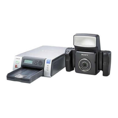
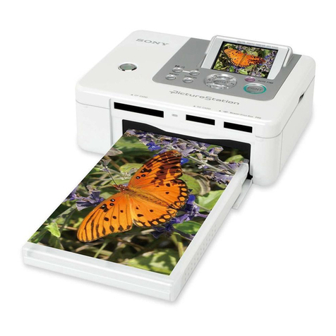
Sony UP-21MD User manual

SONTY.
COLOR
VIDEO
PRINTER
UP-21MD
SERVICE
MANUAL
Volume
1
1st
Edition

ABS
COV=ay
Wis,
Y-CARATCT.
BERN,
TOVIASIVITMRMAINERBCRT,
AM,
SHRED
CMB®KR,
ABEBRIZDBEMSZTEMBVET.
ERE
SIT
S7=ED,
V-EARKL—-AMT>
VF
tSureewmisOaCHAS
ES.
4\
WARNING
This
manual
is
intended
for
qualified
service
personnel
only.
To
reduce
the
risk
of
electric
shock,
fire
or
injury,
do
not
perform
any
servicing
other
than
that
contained
in
the
operating
instructions
unless
you
are
qualified
to
do
so.
Refer
all
servicing
to
qualified
service
personnel.
4,
WARNUNG
Die
Anleitung
ist
nur
fiir
qualifiziertes
Fachpersonal
bestimmt.
Alle
Wartungsarbeiten
diirfen
nur
von
qualifiziertem
Fachpersonal
ausgefiihrt
werden.
Um
die
Gefahr
eines
elektrischen
Schiages,
Feuergefahr
und
Verletzungen
zu
vermeiden,
sind
bei
Wartungsarbeiten
strikt
die
Angaben
in
der
Anieitung
zu
befoigen.
Andere
ais
die
angegeben
Wartungsarbeiten
diirfen
nur
von
Personen
ausgefiihrt
werden,
die
eine
spezielle
Befahigung
dazu
besitzen.
4
AVERTISSEMENT
Ce
manual
est
destiné
uniquement
aux
personnes
compétentes
en
charge
de
|’entretien.
Afin
de
réduire
les
risques
de
décharge
électrique,
d’incendie
ou
de
blessure
n’effectuer
que
les
réparations
indiquées
dans
le
mode
d’emploi
&
moins
d’étre
qualifié
pour
en
effectuer
d’autres.
Pour
toute
réparation
faire
appel
@
une
personne
compétente
uniquement.
UP-21MD
V1

’:
Mechanical
Trouble
NG
Code
List
NG_CODEi
Display
message
NGcommand
NG
data
Contents
of
NG
Symptom
Cheking
point
Example
of
possible
cause
MECHA
TROUBLE
Ei
08
HEAD_HOME_TIME_OUT
Cannot
move
head
to
head
up
position,
time
runs
out
+
Relation
of
OC
motor
«
DC
motor
harness
is
not
connected.
HEAD
og
HEAD_HOME_PICK_TIMEOUT
Cannot
move
head
from
head
up
to
paper
pick
Position,
time
runs
out
“MEC-15/CN202,
CN205,
IC203”
¢
Sensor
harness
is
not
connected.
0a
HEAD_PICK_HALF1_TIMEOUT
Cannot
move
head
from
paper
pick
to
head
half
position,
time
runs
out
“SY-299/CN302,
IC302”
+
Overload
is
applied
to
mechanical
block.
Ob
HEAD_HALF1_DOWN1_TIMEOUT
—
Cannot
move
head
from
head
half
to
Y
print
position,
time
runs
out
+
Relation
ot
sensor
«
Head
cam
FG
has
damaged.
Oc
HEAD_DOWN1_HALF2_TIMEOUT
Cannot
move
head
from
Y
print
to
head
half
position,
time
runs
out
"MEC-15/CN101,
CN104”
etc.
10
HEAD_HALF2_DOWN2_TIMEOUT
Cannot
move
head
from
head
half
to
M
print
position,
time
runs
out
*SY-299/CN301,
IC302”
1
HEAD_DOWN2_HALF3_TIMEOUT
Cannot
move
head
from
M
print
to
head
half
position,
time
runs
out
S8/S9
12
HEAD_HALF3_DOWN3_TIMEOUT
—
Cannot
move
head
from
head
half
to
C
print
position,
time
runs
out
13
HEAD_DOWN3_HALF4
TIMEOUT
Cannot
move
head
from
©
print
to
head
half
position,
time
runs
out
14
HEAD_HALF4_DOWN4_TIMEOUT
—
Cannot
move
head
from
head
half
to
L
print
position,
time
runs
out
15
HEAD_DOWN4_HOME_TIMEOUT
—
Cannot
move
head
from
L
print
to
head
up
position,
time
runs
out
16
HEAD_DOWN3_HOME_TIMEOUT
Cannot
move
head
from
C
print
to
head
up
position,
time
runs
out
17
HEAD_PICK_HALF2_TIMEOUT
Cannot
move
head
from
paper
pick
to
head
half
position,
time
runs
out
if
HEAD_POS_ERROR
Cannot
detect
head
position
td
HEAD_COLD_ERROR
Detects
the|abnormal
temperature
of
thermal
head
thermistor
.
+
Thermal
head
+
Thermal
head
has
failed.
te
HEAD_HEAT_TIMEOUT
on
tise’
the
regular
temperature
during
pre-heating
of
a
thermal
head,
time
runs
“SY-299/CN401,
IC302”
+
Thermal
head
hamess
is
not
connected
or
damaged
etc,.
ou
CHECK
RIBBON
E1
34
RIBBON_MCL_TIMEOQUT
Detects
index
mark
during
magenta
or
cyan
indexing
of
an
ink
ribbon
by
sensor
$3,
+
Relation
of
DC
motor
+»
Sensor
harness
is
not
connecied.
time
runs
out
;
“MEC-15/CN202,
CN205,
IC203”
+
Ribbon
take-up
torque
incorrectly.
"SY-299/CN302,
IC302”
ete.
+
Relation
of
sensor
“MEG-15/CN101,
CN103,
IC101,
IC104”
“SY-299/CN301,
1C302”
$3
AO
CHECK
RIBBON
Detects-an
unused
ribbon
by
a
ribbon
type
detect
sensor
0
to
2
(S5
to
S7)
“MEC-15/CN101,
CN103,
10101,
IC105"
*
Type
reflection
port
of
an
ink
ribbon
has
failed.
“SY-299/CN301,
IC302”
+
Sensor
harness
is
not
connected.
$5-S7
+
Optical
axis
is
out
of
place
because
of
sensor
board
is
installed
incorrectly.
MECHA
TROUBLE
Et 51
LOAD_TMG_TIMEOUT
Printing
paper
is
not
fed
until
a
feed
sensor
(S2)
when
feeding
paper,
time
runs
out
+
Relation
of
DC
motor
+
Sensor
hamess
is
not
connected.
LOAD
ICHECK
PAPER
LOAD
i
ye
et
a
a
eS
SSeS
UP-21MD
V1
()
“MEG-15/CN202,
CN205,
IC203”
“SY-299/CN302,
IC302”
*
Relation
of
sensor
“MEGC-15/CN101,
CN103,
IC101,
1C103”
“SY-299/CN301,
1C302”
$2
+
Paper
feed
is
fault
by
reduce
of
friction
on
paper
feed
roller.
:
+
Paper
feed
tray
has
damaged.
ete.
(Continued)

(Continued
of
NG_CODE1)
Display
message
NGcommand
NGdata
Contents
of
NG
Sympiom
Cheking
point
Example
of
possible
cause
MECHA
TROUBLE
E14
52
PULLIN_TMG_TIMEOUT
Printing
paper
cannot
be
pulled
in
from
a
paper
feed
sensor
($2).to
the
inside
of
aunit
°
Relation
of
stepping
motor
*
Stepping
motor
hamess
is
not
connected.
ene
PAPER
when
feeding
paper,
time
runs
out
“MEC-15/CN202,
CN206,
IC204”
+
Sensor
hamess
is
not
connected.
LOAD
56
LOAD_PAPER_SHORT
Detects
short
paper
during
load
by
a
paper
feed
sensor
(S2)
when
feeding
paper,
time
“SY-299/CN302,
IC302”
+
Loss
of
synchronism
in
a
stepping
motor.
runs
out
-
:
«
Relation
of
sensor
*
Overload
is
applied
to
grip
roller
mechanism.
MECHA
TROUBLE
E14
58
PUSHOUT_TMG_TIMEOUT
Print
paper
cannot
be
pushed
out
from
the
inside
of
a
unit
to
a
paper
feed
sensor
(S2)
“MEC-15/CN101,
CN103,
IC101,
IC103”
*
Overlapped
paper
feed.
Roe
PAPER
when
paper
ejection,
time
runs
out
“SY-299/CN301,
IC302”
etc.
EJECT
59
EJECT_TMG_TIMEOUT
Printing
paper
cannot
be
ejected
from
paper
feed
sensor
(S2)
to
the
outside
of
a
unit
$2
when
paper
ejection,
time
runs
out
MECHA
TROUBLE
E1
61
PP_LD_MISSING_ERR
Detects
paper
is
not
existed
under
paper
exist
timing
conditions
by
a
paper
feed
*
Relation
of
stepping
motor
*
Sensor
harness
is
not
connected.
PROCESS
sensor
(S2)
when
retracting
paper
“MEC-15/CN202,
CN206,
IC204"
+
Overload
is
applied
to
grip
roller
mechanism.
62
PP_LD_JAM_ERR
Detects
paper
exist
under
paper
is
not
existed
timing
conditions
by
a
paper
feed
“SY-299/CN302,
10302”
*
Loss
of
synchronism
in
a
stepping
motor.
sensor
(S2)
when
retracting
paper
+
Relation
of
sensor
etc.
“MEC-15/CN101,
CN103,
IC101,
IC103”
“SY-299/CN301,
IC302”
$2
63
PP_JAM_ERR
Detects
paper
exist
under
paper
is
not
existed
timing
conditions
by
a
jamming
sensor
»
Relation
of
stepping
motor
*
Sensor
harness
is
not
connected.
(S10)
when
retracting
paper
“MEC-15/CN202,
CN206,
IC204”
+
Overload
is
applied
to
stepping
motor
mechanism.
64
PP_JAM_MISSING_ERR
Detects
paper
is
not
existed
under
paper
exist
timing
conditions
by
a
jamming
sensor
“SY-299/CN302,
IC302”
+
Loss
of
synchronism
in
a
stepping
motor.
($10)
when
retracting
paper
*
Relation
of
sensor
*
Overlapped
paper
feed.
65
PP_PRINT_TIMEOUT
Long
time
is
spent
in
printing,
time
runs
out
“MEC-15/CN101,
CN105”
etc.
“SY-299/CN301,
IC302”
eee
S10
MECHA
TROUBLE
Et
73
RBN_CD_ALARM
Fall
detection
level
of
a
ribbon
cueing
detect
sensor
(S3)
*"MEC-15/CN101,
CN103,
IC101,
IC103-
*
Deterioration
in
sensitivity
of
sensor
due
to
dust
etc,.
SENSOR
74
PAPER_LD_ALARM
Fall
detection
level
of
a
paper
in
sensor
($1)
iC105"
75
PAPER_IN_ALARM
Fall
detection
level
of
a
paper
feed
sensor
(S2)
“SY-299/CN301,
IC302”
76
RBN_TYPEO_ALARM
Fall
detection
level
of
a
ribbon
type
detect
sensor
0
{S5)
Each
sensor
(S1-S7)
77
RBN_TYPE1_ALARM
Fall
detection
level
of
a
ribbon
type
detect
sensor
1
(S6)
78
FABN_TYPE2_ALARM
Fall
detection
level
of
a
ribbon
type
detect
sensor
2
(S7)
7f
ROOM_HEAT_ERROR
Detects
abnormal
high
temperature
in
a
room
thermistor
“MEC-15/THP201,
CN202”
*
Defective
of
harness
etc,.
“SY-299/CN302,
IC302”
(ii)
(ii)
UP-27MD
V1

A
way
at
looking
the
list:
For
NG_CODE2
to
5,
refer
to
HEX
code
converting
as
binary.
(Example
For
h’42
=
0100
0010:
sixth
bit
and
first
bit)
NG_CODE2
NG
command
NG
data
Conients
of
NG
Symptom
Cheking
point
.
Example
of
possible
cause
E2
BIT2
PAPER_JAM_SENS
Defective
of
a
jamming
sensor
(S10)
detection
(when
“MEC-1
S5/CN101,
CN105”
*
Sensor
harness
is
not
connected.
mechanism
adjustment)
“SY-299/CN301,
[C302”
*
Sensor
board
is
installed
incorrectly.
$10
BIT
1
PAPER_EJ_SENS
Deiective
of
a
delivery
flap
sensor
(S11)
detection
(when
:
“MEC-15/CN101,
CN106”
mechanism
adjustment)
“SY-299/CN301,
IC302”
Sit
BITO
DOOR_SENS
Defective
of
a
front
panel
opening
sensor
detection
(when
SE-642
mechanism
adjustment)
“"KEY-49/CN301,
CN302”
“SY-299/CN203,
IC302”
NG_CODE3
*
NG
command
NG
data
Contents
of
NG
Symptom
Cheking
point
Example
of
possible
cause
{
3
BITS
HEAD
THERMISTOR
Defective
of
a
temperature
detection
of
a
head
thermistor
(when
Thermal
head
*
Thermal
head
hamess
is
not
connected.
BITS
mechanism
adjustment)
“SY-299/CN401,
IC302”
ete.
BIT4
ROOM
THERMISTOR
Defective
of
temperature
detection
of
a
room
thermistor
“MEC-15/THP201,
CN202”
*
Harness
is
not
connected.
BIT3
{THP201
on
the
MEC-15
board)
(when
mechanism
adjustment)
“SY-299/CN302,
IC302”
BITO
EEPROM
Cannot
write
or
read
correctly:in
EEPROM
(!C102
on
the
MEC-
“MEC-15/1C102,
CN101”
*
Haress
is
not
connected.
i
15
board)
(when
mechanism
adjustment)
“SY-299/CN301,
1C302”
NG_CODE4
NG
command
NG
data
Contents
of
NG
Symptom
Cheking
point
Example
of
possible
cause
£4
BIT5
RBN_CD_SENS
Defective
of
a
ribbon
cueing
sensor
(S3)
detection
(when
“MEC-15/CN101,
CN103,
[C101,
1IC104”
+
Sensor
harness
is
not
connected.
BIT
4
mechanism
adjustment)
“SY-299/CN301,
IC302”
+
Optical
axis
is
out
of
place
because
of
sensor
board
is
installed
incorrectly.
$3
BIT3
PAPER_LD_SENS
Defective
of
a
paper
feed
sensor
(S2)
detection
(when
“MEC-15/GN101,
CN103,
IC101,
10103”
BIT2
mechanism
adjustment)
“SY-299/CN301,
IC302”
$2
(
BIT1
PAPER_IN_SENS
Defective
of
a
paper
in
sensor
(S1)
detection
(when
mechanism
“MEC-15/CN101,
CN103,
10101,
[C103”
BITO
adjustment)
“SY-299/CN301,
IC302”
$1
UP-2IMDVI
(til)
(iii)

NG_CODES5
NG
command
NG
data
Contents
of
NG
Symptom
Cheking
point
Example
of
possible
cause
E5
BITS
RBN_TYPE_SENS2
Defective
of
a
ribbon
type
sensor
2
(S7)
detection
(when
“MEC-15/CN101,
CN103,
1C101,
IC105”
*
Sensor
hamess
is
not
connected.
BIT
4
mechanism
adjustment)
“SY-299/CN301,
IC302”
*
Optical
axis
is
out
of
place
because
of
sensor
board
is
installed
incorrectly.
$7
BITS
RBN_TYPE_SENS1
Defective
of
a
ribbon
type
sensor
1
(S6)
detection
(when
“MEC-15/CN101,
CN103,
10101,
IC105”
BIT2
mechanism
adjustment)
“SY-299/CN301,
IC302”
$6
BIT1
RBN_TYPE_SENSO
Defective
of
a
ribbon
type
sensor
0
($5)
detection
(when
“MEC-15/CN101,
CN103,
IC101,
IC104”
BITO
mechanism
adjustment)
“SY-299/CN301,
C302”
$5
(iv)
(iv)
UP-21MD
V1

de
Table
of
Contents
Manual
Structure
Purpose
of
this
manual
Related
manuals
1.
Service
Information
Pols.
©
Board!
Locathom
edcccsesest
sacesszssccsecdeveavicossstecestvcacsoscuvandacsesacessetetldasscenssaiiusvase
1-2.
Main
Parts
Location
1-3.
Removal
and
Installation
of
Cabinet
.............cccisscssssssecsessssssstescessessssavaseesane
1-2
7
W321...
TOp
Cover
isccccicscostecestcs
carsacssdhetctteodecluacsdsivesseosdecceiasndesivednavedests
1-2
1-3-2.
Ribbon
Panel
Assembly
.........ccsssssecscsssecececsssescesacseecsesssnsessens
1-2
1-3-3.
Front
Panel
Assembly
oo...
.ccsssscsssscoressssscscssssesseccessnessereessenees
1-3
1-4.
Replacement
of
Main
Parts
00...
ccssssssscsssscssssssesssesecssssssscsesesessecsseseeceseess
1-4
1-4-1.
Mechanical
Deck
Assembly
...........cscssssscssscssessecssceseossersescseeesas
1-4-2.
1-4-3.
1-4-4,
1-4-5.
1-4-6.
1-4-7.
1-4-8.
S2/RIBBON
Sensor
Board...
1-4-9.
S14
Sensor
Board
......scsssscssssssesssesesessssscescsesssessseeseeseesensaseeaes
1-4-10.
S8/S9
Sensor
Board...
essssessceessssssssssscscsssesenesesssssceseseseaees
1-4-11.
Eject
Roller
Assembly
............ssessesececcnsssserecsesorsrssescsesseseseees
1-4-12.
Photo
Sensor........ccssscsssossecsssssccscesesersenesessssscssnanesseseescneneassess
1-4-13.
Interlock
Switch
Assembly
..............ccsssssssssseseccessssessessesesseeens
2.
Electrical
Alignment
and
Mechanical
Alignment
2-1.
Electrical
Adjustment
.........ccccssssessscsessecssesascesssreccsssessssessssscssecsseacasensavereees
2-1
2-1-1.
Density
Adjustment
during
Thermal
Head
Replacement
..........
2-1
2-1-2.
Output
of
Test
Pattern
(Internal
Signal)
in
Service
Mode
.........
2-3
2-1-3.
Electrical
Adjustment
(Analog
Video
Block)
...........sssecssssseseees
2-4
2-2.
Mechanical
Adjustment
.............cssssesssssssccsecssecessseseotscsssssnescneseerssstsneneens
2-2-1.
Mechanical
Adjustment
Mode
2-2-2.
Entering
the
Mechanical
Adjustment
Mode
............csssssssseseees
2-8
2-2-3.
Normal
Operation
Check
and
Automatic
Adjustment
...............
2-9
we
3.
Sensor
Arrangement
and
Functional
Description
UP-21MD
V1

4.
Circuit
Operation
Description
4-1,
Digital
Video
Signal
Processing
BIOCK
........c..sccsssscssssssecescsssessessegeccssssseesses
4-1
Adeh.,
cOuiline
seceiicciic
cesdedascesssatse
gan
cieasteantusctcaeaeselcasheesstustanedescsecsesse
4-1
4-1-2.
Flow
of
Image
Signal
in
Each
Operating
Mode
.......s...sssscessseeees
4-2
4-1-3.
Basic
Operation
Timing
and
CPU
BIOck
....ccccscsscssssescssccesssssesees
4-6
4-1-4,
Memory
(DRAM)
BIOCK
.......cccecsssssssssssesssssssscsessvssssesncenecsesaces
4-10
4-1-5.
Memory
Control
BIOck
.........ccccscsscssssssssssccsssssssccecsesessessersuesseee
4-11
4-1-6.
Color
Adjustment
Block
.........c.cccscssssssssssssesesecessessssecsessesscseees
4-13
4-1-7.
Sampling
Clock
Generation
BlOCk
......ssscssssscsssessccececssessesssessees
4-14
4-1-8.
Masking
BLOCK
.......ccccsssssssssssssscsscsssscsccsussecsecessssrssessesaseasezeseces
4-1-9.
A/D
and
D/A
Conversion
Blocks
4-2,
Analog
Video
Signal
Processing
BIOCK
.......c.ssscscsscesssscessssessesessssesesseesonee
4-2-1,
Outline
one
esesecscesstsessesseeceessvees
4-2-2.
Interface
Block
(IF-851
Board)
4-2-3.
Analog
Video
Signal
Processing
Block
4-3.
Operation
Description
of
Print
Control
Block
Circuit
(Part
of
VPR-74
Board)
Oreo
renennoreneenaveersese
senses
eee
esessseneseeseerenesees
dev
ereeereevencccccveescneeses
4-3-1,
CPU
Flowchart
..........ccssssssssssssssssssssscescscsesesecsercacacsesscevesssseeses
4-3-2.
CPU
(1C302)
Memory
Map
........sscsssssssssecssessnssssssseosssecseecsneenes
4-3-3.
Outline
of
Motor
Drive
Function
BIOcks
......c.cccessssescessssssseseees
4-3-4.
Outline
of
Sensor
Detection
Circuits
.........ccccsccsscsscecessscsssscseees
4-3-5.
Head
Control
BIOcK
........csccssssssssssssssosesasscssscessscessarsecsuscessucssees
4-4,
Circuit
Operation
Description
of
System
Control
Block
4-4-1.
Special
Mode
and
Special
Operating
Method
4-4-2.
Address
Map
......ssscssscssssssssssssessessssssssesstsseeseonee
4-4-3,
Circuit
Operation
..........sccsccssesssssssssessseessssenees
‘
4-4-4,
Communication
with
Internal
CPU
in
Unit
.......c.cccccssssssssseoes
4-4-5.
Analog
Video
Block
(VA)
Control
on
the
VPR-74
Board
......
4-36
4-4-6.
RS
Communication
Control
......c.cccscssssssssssesssssscscceverscsesessecese
4-4-7.
|
Media
Protection
such
for
Software
5.
Troubleshooting
5-1.
Video
(Image)
Related
Trouble
..........ccscsssscsessscssececsesecsesesectessessssesscsseeenees
5-1
5-2.
Mechanical
Troubleshooting
.........c.sssssssssssessesssssessssseesiecuecuscarssessecssecenessess
5-3
Mechanical
Trouble
NG
Code
List
UP-21MD
V1

Purpose
of
this
manual
Related
manuals
UP-21MD
V1
Manual
Structure
This
manual
is
the
Service
Manual
Vol.1
of
the
Color
Video
Printer
UP-21MD.
This
manual
contains
the
service
information,
electrical
alignment
and
mechanical
alignment,
sensor
arrangement
and
functional
description,
circuit
operation
description
and
troubleshooting.
In
addition
to
this
Service
Manual
Vol.1,
the
following
manual
is
provided.
*
Service
Manual
Vol.2
Part
No.:
9-955-307-21
(for
J,
UC,
CE)
Contains
the
semiconductor
pin
assignment,
spare
parts,
block
diagrams,
schematic
diagrams
and
board
layouts.
*
Instruction
Manual
Part
No.:
3-206-154-11
This
manual
describes
the
information
required
for
the
actual
management
and
operation
of
this
unit.
*
“Semiconductor
Pin
Assignments”
CD-ROM
(Available
on
request)
This
“Semiconductor
Pin
Assignments”
CD-ROM
allows
you
to
search
for
semiconductors
used
in
B&P
Company
equipment.
Semiconductors
that
cannot
be
searched
for
on
this
CD-ROM
are
listed
in
the
service
manual
for
the
corresponding
unit.
The
service
manual
contains
a
com-
plete
list
of
all
semiconductors
and
their
ID
Nos.,
and
thus
should
be
used
together
with
the
CD-ROM.
Part
number:
9-968-546-XX

o

Section
1
1-1.
Board
Location
SW-1081
board
VPR-74
board
IF-851
board
IF-852
board
MEC-15
board
SY-299
board
SE-642
board
S2/RIBBON
sensor
board
$11
sensor
board
$8/S9
sensor
board
$1
sensor
board
UP-21MD
V1
Service
Information
1-2.
Main
Parts
Location
Stepping
motor
Switching
regulator
DC
motor
Mechanical
deck
assembly
1-1

nstaiiation
of
Cabinet
1-3-2.
Ribbon
Panel
Assembly
1
¢
al
@
=|
ro}
<
2.
ie]
poe
a.
1-3-1.
Top
Cover
1.
Remove
the
top
cover.
(Refer
to
Section
1-3-1.)
2.
Pull
out
the
paper
tray
assembly
in
the
direction
1.
Remove
the
five
M3
case
fixing
screws
and
then
indicated
by
arrow
@).
remove
the
top
cover.
3.
Release
the
door
eject
lever
and
pull
out
the
ribbon
panel
assembly
in
the
direction indicated
by
arrow
@).
4.
Pull
out
the
print
media
in
the
direction
indicated
by
arrow
@).
Top
cover
M3
case
fixing
screw
Print
media
M3
case
fixing
screw
_-
Paper
tray
assembly
5.
Remove
the
four
screws
and
thrust
retainer
boss,
and
then
open
the
VPR-74
board
in
the
direction
indicated
by
the
arrow.
-
6,
Disconnect
the
flexible
flat
cable
from
the
connector
2.
Re-attach
the
top
cover
in
the
reverse
order
of
step
1.
(CN203)
on
the
SY-299
board.
VPR-74
board
SY-299
board
Flexible
flat
cable
1-2
UP-21MD
V1

7.
Remove
the
front
panel.
(Refer
to
Section
1-3-3.)
8.
Remove
the
two
screws
(BVTT
3
X
6)
and
then
remove
the
door
stoppers
((L)
and
(R)).
9.
Insert
pins
into
the
two
holes
of
sliders
and
remove
the
ribbon
panel
assembly.
10.
Remove
the
two
screws
(BVTT
3
x
6)
and
four
claws,
then
remove
the
ribbon
panel.
11.
Disconnect
one
flexible
flat
cable
and
one
harness
from
the
connectors
(CN301
and
CN302)
on
the
KEY-
49
board.
12.
Remove
the
four
screws
(BVTT
3
X
6),
then
remove
the
KEY-49
board.
13.
Remove
the
four
screws
(BVTT
3
xX
6),
then
remove
the
front
plate
assembly.
14.
Remove
one
screw
(PTT
2
X
10),
then
remove
the
interlock
plate
and
SE-642
board.
Door
stopper
(L)
Front
panel
assembly
Ribbon
pane!
assembly
Slider
Door
stopper
(R)
Connector
Door
front
(CN301)
plate
assembly
Flexible
flat
cable
Door
base
assembly
15.
Re-attach
the
ribbon
panel
assembly
in
the
reverse
order
of
steps
1
to
14.
UP-21MD
V1
=
1.
1-3-3.
Front
Panei
Assembiy
Remove
the
top
cover.
(Refer
to
Section
1-3-1.)
Remove
the
paper
tray
assembly.
(Refer
to
Section
1-
3-2.)
Remove
the
ribbon
panel
assembly.
(Refer
to
Section
1-3-2.)
Remove
the
four
screws
and
four
claws
and
then
remove
the
front
panel
assembly.
Front
panel
assembly
5.
Re-attach
the
front
panel
assembly
in
the
reverse
order
of
steps
1
to
4.

4
A
a
£m.
i
-4.
Repiacemeni
of
Main
Paris
1-4-1.
Mechanical
Deck
Assembly
1.
Remove
the
top
cover.
(Refer
to
Section
1-3-1.)
2.
Disconnect
the
four
flexible
flat
cables
and
one
harness
from
the
connectors
(CN102,
CN301,
CN401,
CN601,
and
CN901)
on
the
VPR-74
board.
3.
Remove
the
ribbon
panel
assembly.
(Refer
to
Section
1-3-2.)
4.
Remove
the
front
panel
assembly.
(Refer
to
Section
1-
3-3.)
5.
Disconnect
the
four
flexible
flat
cables
from
the
connectors
(CN201,
CN301,
CN302,
and
CN401)
on
the
SY-299
board.
6.
Remove
the
four
screws,
then
remove
the
SY-299
board
and
mechanical
partition
plate.
Flexible
flat
cables
Connector
(CN102)
Connecto
;
(CN901)
Flexible
Connector
vg
flat
cables
(CN401)
Connector
(CN601)
Connector
(CN301)
Connector
(CN401)
Mechanical
partition
plate
Remove
the
two
screws
and
then
remove
the
front
stay
assembly.
Remove
the
power
button,
then
remove
the
power
switch
rod.
UP-21MD
V1

9.
Remove
the
two
screws
(B
4
X
20)
and
then
remove
the
DC
fan.
10.
Disconnect
the
two
harnesses
from
the
connectors
(CN201
and
CN207)
on
the
MEC-15
board.
11.
Disconnect
one
harness
connected
to
the
thermal
head
from
the
switching
regulator.
12.
Remove
the
four
screws
(BVTT
3
X
6)
and
then
remove
the
mechanical
deck
assembly
in
the
direction
indicated
by
the
arrow.
MEC-15
board
Connector
Connector
(CN201)
(CN207)
Harnesses
Switching
regulator
UP-21MD
Vi
13.
Disconnect
the
five
harnesses
from
the
connectors
(CN105,
CN203,
CN204,
CN205,
and
CN206)
and
the
four
flexible
flat
cables
from
the
connectors
(CN102,
CN103,
CN104,
and
CN106).
14.
Remove
the
three
screws
and
then
remove
the
MEC-
15
board.
Flexible
flat
cable
Harnesses
exe
Connector
at
cables
OO
assess
parted
al
(CN205
KONE)
Mechanica!
\
Connector
deck
(CN102)
assembly
Connector
~.
‘CN203)
Connector
(CN104)
Connector
Connector
(CN106)
N105)
Connector
(CN103)
MEC-15
board
15.
Attach
mechanical
deck
assembly
in
the
reverse
order
of
steps
1
to
14.
1-5

1-4-2.
riead
Assembiy
1-4-3.
DC
Fan
1.
Remove
the
top
cover.
(Refer
to
Section
1-3-1.)
;
1.
Remove
the
top
cover.
(Refer
to
Section
1-3-1.)
2.
Remove
the
ribbon
panel
assembly.
(Refer
to
Section
2.
Open
the
VPR-74
board.
(Refer
to
Section
1-3-2.)
1-3-2.)
3.
Pull
out
the
ribbon
panel
assembly
and
disconnect
one
3.
Remove
the
front
panel
assembly.
(Refer
to
Section
1-
flexible
flat
cable
from
the
connector
(CN203)
on
the
3-3.)
SY-299
board.
4,
Remove
the
mechanical
deck
assembly.
(Refer
to
4.
Remove
the
four
screws.
Section
1-4-1.)
5.
Disconnect
one
harness
from
the
connector
(CN204)
on
the
MEC-15
board.
6.
Remove
the
two
screws
(M
3
x
14),
and
then
remove
Connector
the
DC
fan.
.
sone)
7.
Remove
the
two
screws
(M
2.5
x
8),
then
remove
the
head
assembly.
To
switching
regulator
iss
To
SY-299
~~)
board
Ribbon
panel
assembly
Thermal
Connector
‘CN204)
Harness
8.
Attach
head
assembly
in
the
reverse
order
of
steps
1
to
7.
When
attaching
the
head
assembly,
set
the
assembly
in
the
direction
indicated
by
the
arrow,
then
tighten
the
two
screws.
1-6
UP-21MD
V1

5.
Open
the
SY-299
board
and
mechanical
partition
plate
1-4-4.
DC
Motor
Assembly
in
the
direction
indicated
by
the
arrow.
6.
Remove
the
two
screws,
then
remove
the
DC
fan.
1.
Remove
the
top
cover.
(Refer
to
Section
1-3-1.)
7.
Disconnect
the
harness
from
the
connector
(CN204)
2.
Remove
the
ribbon
panel
assembly.
(Refer
to
Section
on
the
MEC-15
board.
1-3-2.)
3.
Remove
the
front
panel
assembly.
(Refer
to
Section
1-
3-3.)
4.
Remove
the
mechanical
deck
assembly.
(Refer
to
Section
1-4-1.)
5.
Remove
the
three
screws
(M
2.6
X
4)
and
then
remove
the
DC
motor
bracket.
6.
Remove
the
winding
gear
assembly,
wheel
gear,
planetary
gear
1
assembly,
and
two
DC
gear
bearings.
vod
haan
7.
Cut
the
three
bands.
harmnee
8.
Remove
the
two
screws
(M
3
X
4)
and
then
remove
cea
Gaia
the
DC
motor
assembly.
Remove
one
harness
from
the
connector.
ALOSs
LPO
tf
VPR-74
board
Pee
ESS
Y
‘Oo
‘
ps\
eS
=f
OI
teoNG,
ak?)
Connector
z
(CN204)
MEC-15
board
’
Planetary
gear
1
assembly
MEC-15
board
Mechanical
partition
plate
8.
Attach
DC
fan
in
the
reverse
order
of
steps
1
to
7.
Dealing
Winding
gear
assembly
10.
Attach
a
new
DC
motor
assembly
in
the
reverse
order
of
steps
1
to
9.
UP-21MD
V1
1-7

1-4-5.
Siepping
Motor
Assembiy
1,
Remove
the
top
cover.
(Refer
to
Section
1-3-1.)
2.
Remove
the
ribbon
panel
assembly.
(Refer
to
Section
1-3-2.)
3.
Remove
the
front
panel
assembly.
(Refer
to
Section
1-
3-3.)
4,
Remove
the
mechanical
deck
assembly.
(Refer
to
Section
1-4-1.)
5.
Disconnect
one
harness
from
the
connector
(CN206)
on
the
MA-15
board.
6.
Disconnect
the
harness
from
the
stepping
motor
assembly.
7.
Remove
the
two
screws
and
then
remove
the
stepping
motor
assembly.
Harness
Stepping
motor
assembly
-
MEC-15
board
Connector
(CN206)
8.
Attach
stepping
motor
assembly
in
the
reverse
order
of
steps
|
to
7.
When
attaching
the
stepping
motor
assembly,
set
the
assembly
in
the
direction
indicated
by
the
arrow,
then
tighten
the
two
screws.
1-4-6.
Grip
Belt
1.
Remove
the
top
cover.
(Refer
to
Section
1-3-1.)
2.
Remove
the
ribbon
panel
assembly.
(Refer
to
Section
1-3-2.)
3.
Remove
the
front
panel
assembly.
(Refer
to
Section
1-
3-3.)
4.
Remove
the
mechanical
deck
assembly.
(Refer
to
Section
1-4-1.)
5.
Remove
the
sensor
guide
assembly
and
tray
guide
assembly.
(Refer
to
Section
1-4-7.)
6.
Remove
the
stepping
motor
assembly.
(Refer
to
Section
1-4-5.)
7.
Remove
the
three
screws
and
then
remove
the
stepping
motor
bracket.
8.
Remove
the
grip
belt.
M
2.6x4
Stepping
motor
bracket
9.
Attach
a
new
grip
belt
in
the
reverse
order
of
steps
1
to
8.
UP-21MD
V1

mae
1-4-7.
S11
Sensor
Board
1...
Remove.the
top-cover.-(Refer-to-Section
1-3-1.)-
Remove
the
ribbon
panel
assembly.
(Refer
to
Section
1-3-2.)
3.
Remove
the
front
panel
assembly.
(Refer
to
Section
1-
3-3.)
4.
Remove
the
mechanical
deck
assembly.
(Refer
to
Section
1-4-1.)
5.
Remove
the
four
screws
(M
2.6
X
4)
and
then
remove
the
front
beam.
6.
Remove
one
screw
(M
2.6
X
6)
and
then
remove
the
electrostatic
plate
spring.
Remove
the
two
screws
(M
2
X
6),
washer
and
four
claws,
then
remove
the
sensor
guide
assembly.
8.
Remove
the
two
screws
(M
2.6
X
4)
and
then
remove
the
tray
guide
assembly.
9.
Disconnect
one
flexible
flat
cable
and
remove
the
S11
sensor
board.
Sensor
guide
ae
assembly
Flexible
flat
cable
Electrostatic
plate
spring
ae
Front
beam
10.
Attach
a
new
S11
sensor
in
the
reverse
order
of
steps
1
to
9.
UP-21MD
V1
1-4-8.
S2/RIBBON
Sensor
Board
1.
Remove-the-top-cover.-(Refer
to-Section-1-3-1:)-
2.
Remove
the
ribbon
panel
assembly.
(Refer
to
Section
1-3-2.)
3.
Remove
the
front
panel
assembly.
(Refer
to
Section
I-
3-3.)
4.
Remove
the
mechanical
deck
assembly.
(Refer
to
Section
1-4-1.)
5.
Remove
the
tray
guide
assembly.
(Refer.to
Section
1-
4-7.)
6.
Remove
the
four
claws
and
then
remove
the
sensor
guide
assembly.
7.
Remove
the
electrostatic
plate
in
the
direction
indicated
by
the
arrow.
8.
Remove
the
three
claws,
disconnect
one
flexible
flat
cable,
and
remove
the
S2/RTBBON
sensor
board.
Sensor
guide
assembly
Flexible
flat
S$2/RIBBON
sensor
board
9.
Attach
S2/RIBBON
sensor
board
in
the
reverse
order
of
steps
1
to
8.
1-9

1-4-S.
31
Sensor
Board
1-4-10.
S8/S9
Sensor
Board
1.
Remove
the
top
cover.
(Refer
to
Section
1-3-1.)
1.
Remove
the
top
cover.
(Refer
to
Section
1-3-1.)
2.
Remove
the
ribbon
panel
assembly.
(Refer
to
Section
2.
Remove
the
ribbon
panel
assembly.
(Refer
to
Section
1-3-2.)
1-3-2.)
3.
Remove
the
front
panel
assembly.
(Refer
to
Section
1-
3.
Remove
the
front
panel
assembly.
(Refer
to
Section
1-
.
3-3.)
3-3.)
4.
Remove
the
mechanical
deck
assembly.
(Refer
to
4.
Remove
the
mechanical
deck
assembly.
(Refer
to
Section
1-4-1.)
Section
1-4-1.)
5.
Remove
the
tray
guide
assembly.
(Refer
to
Section
1-
5.
Remove
one
screw,
disconnect
one
flexible
flat
cable,
4-7.)
and
remove
the
S8/S9
sensor
board.
6.
Remove
the
two
claws
and
then
remove
the
pick
roller
assembly.
7.
Remove
one
claw,
disconnect
one
flexible
flat
cable,
Flexible
flat
cable
and
remove
the
S1
sensor
board.
|
A
Claws
|
a
¥
sS
Flexible
flat
cable
6.
Attach
a
new
S8/S9
sensor
board
in
the
reverse
order
Si
sensor
board
of
steps
1
to
5.
Pick-roller-assembly
8.
Attach
a
new
S1
sensor
board
in
the
reverse
order
of
steps
|
to
7.
1-10
UP-21MD
V1
Other manuals for UP-21MD
1
Table of contents
Other Sony Printer manuals

Sony
Sony UP-D75 User manual

Sony
Sony UP55MD User manual

Sony
Sony UP-D6500 User manual

Sony
Sony UP-D2500 User manual

Sony
Sony DPP-FP85 Instruction sheet

Sony
Sony UP-D711MD User manual

Sony
Sony FilmStation UP-DF750 User manual

Sony
Sony SnapLab UP-CR15L Instruction manual

Sony
Sony UP-DR80MD User manual

Sony
Sony S-Frame DPP-F800 User manual

Sony
Sony DDP-FP70 User manual

Sony
Sony UP-D895 Guide

Sony
Sony DPP-FP50 Fall 2005 User manual

Sony
Sony UP-DR80 User manual

Sony
Sony UPA-PC100 Installation and operating instructions

Sony
Sony CVP-M1 User manual

Sony
Sony UP-X898MD User manual

Sony
Sony UP-CR10L User manual

Sony
Sony DPP-MP1 User manual

Sony
Sony PICTURE STATION DPP-FP90 Instruction sheet