Sony UP-D70 User manual

Vol. 1 (1st Edition)
DIGITAL COLOR PRINTER
UP-D70/D70A
SERVICE MANUAL

UP-D70/D70A (UC,CE)
MANUAL STRUCTURE
This manual is the Service Manual Vol.1 of the digital color printer UP-D70/D70A.
This manual contains the operating instructions, service information, mechanical
operation, circuit operation description, service mode and trouble shooting.
In addition to this Service Manual Vol.1, the following manual is provided.
• Service Manual Vol.2
Part No. 9-977-350-21 (for J, UC, CE)
Contains the semiconductor pin assignment, spare parts, block diagrams, circuit
diagrams and mounted circuit boards.
• Service Manual
UPK-8802RT (RASTER INTERFACE KIT)
Part No. 9-974-788-01 (for J/CE)
9-974-777-01 (for UC)
Purpose of this manual
Related manuals

TABLE OF CONTENTS
1. OPERATING INSTRUCTIONS ............................................................ 1-1
2. SERVISE INFORMATION
2-1. PROCESS ORDER WHEN REPLACING EACH PART............................. 2-1
2-2. LOCATION OF MAIN PARTS .................................................................... 2-3
2-3. DISASSEMBLY ............................................................................................ 2-4
2-4. ASSEMBLING METHOD OF STEPPING MOTOR ................................. 2-11
3. MECHANICAL OPERATION
3-1. MOTOR.......................................................................................................... 3-1
3-2. TIMING OF MECHANICAL OPERATION ................................................ 3-1
3-3. MECHANICAL SECTION OUTLINE ......................................................... 3-3
3-4. POSITION AND FUNCTION FOR SENSOR .............................................. 3-4
3-5. PRINTING OPERATION DESCRIPTION................................................... 3-5
3-6. TIMING FOR BAR CODE DETECTION .................................................. 3-11
4. CIRCUIT OPERATION DESCRIPTION
4-1. SY-270 BOARD, MEC-11 BOARD CIRCUIT OPERATION
DESCRIPTION .............................................................................................. 4-1
5. SERVICE MODE
5-1. SERVICE MODE........................................................................................... 5-1
5-2. ADJUST MODE ............................................................................................ 5-9
5-3. FMY PRINTING (For UP-D70A only) ....................................................... 5-11
5-4. PRINT CONFIRMATION OF UP-D70 ...................................................... 5-11
5-5. RESET OF EACH KIND SETTING VALUE............................................. 5-12
5-6. NOTE ON THE UNIT TRANSPORTATION ............................................ 5-13
6. TROUBLE SHOOTING
6-1. MECHANICAL SECTION ........................................................................... 6-1
6-2. ELECTRICAL SECTION.............................................................................. 6-3


1-2 UP-D70/D70A (UC,CE)
Table of Contents
Introduction
Preparation
Operation
About this Manual .............................................................4
System Overview ..............................................................5
System Configuration....................................................... 5
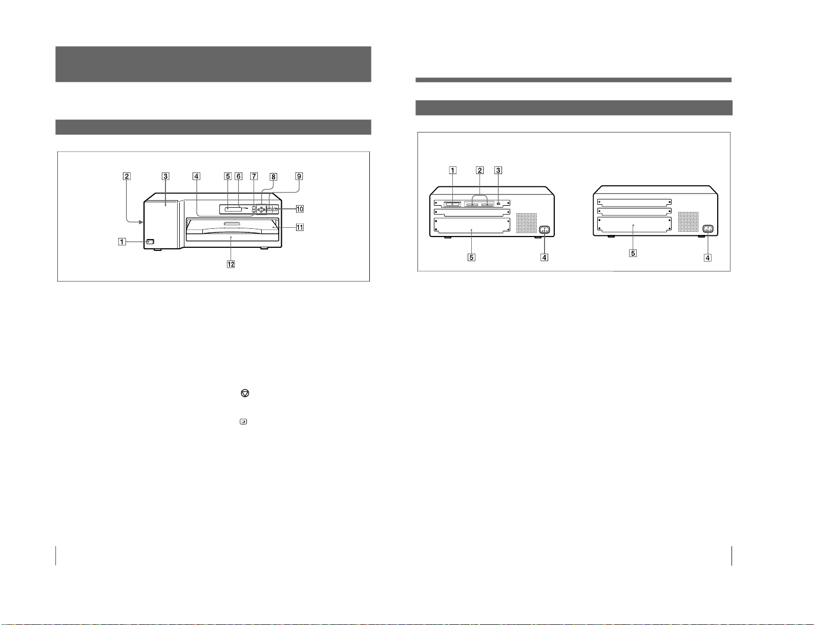
Location and Function of Parts and Controls................6
Front ................................................................................. 6
Rear .................................................................................. 7
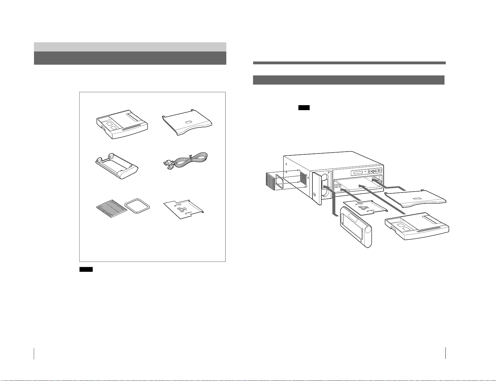
Supplied Accessories.......................................................8
Assembly.......................................................................... 9
Connections ....................................................................10
Connecting the Computer .............................................. 10
Installing the Printer Driver Program............................. 11
Setting the DIP Switch ................................................... 11
Connecting the AC Power Cord..................................... 12
Setting the SCSI Device Type........................................ 13
Before Printing ................................................................14
Loading an Ink Ribbon Cassette .................................... 14
Loading the Print Paper.................................................. 17
Printing.............................................................................19
Setting the Print Quantity...............................................22
Adjusting the Printouts ..................................................23
Adjusting the Gray Balance ...........................................25
Others
Precautions......................................................................27
Safety.............................................................................. 27
Installation...................................................................... 27
On Transportation .......................................................... 28
Cleaning ......................................................................... 28
Ink Ribbon and Print Paper ............................................30
Specifications..................................................................31
Troubleshooting..............................................................32
Error Messages............................................................... 32
If the Paper Jams ............................................................ 34
Index.................................................................................36
3
Table of Contents
2
English
Owner’s Record
The model and serial numbers are located at the rear.
Record these number in the space provided below.
Refer to these numbers whenever you call upon your
Sony dealer regarding this product.
Model No.
Serial No.
WARNING
To prevent fire or shock hazard, do not expose the unit
to rain or moisture.
To avoid electrical shock, do not open the cabinet. Refer
servicing to qualified personnel only.
For the customers in the U.S.A.
This equipment has been tested and found to comply
with the limits for a Class A digital device, pursuant to
Part 15 of the FCC Rules. These limits are designed to
provide reasonable protection against harmful
interference when the equipment is operated in a
commercial environment. This equipment generates,
uses, and can radiate radio frequency energy and, if not
installed and used in accordance with the instruction
manual, may cause harmful interference to radio
communications. Operation of this equipment in a
residential area is likely to cause harmful interference in
which case the user will be required to correct the
interference at his own expense.
You are cautioned that any changes or modifications not
expressly approved in this manual could void your
authority to operate this equipment.
This device requires shielded interface cables to comply
with FCC emission limits.
As an
E
NERGY
S
TAR
Partner, Sony Corporation
has determined that this
product meets the
ENERGY STAR guidelines
for energy efficiency.
Outline of the International ENERGY
STAR Office Equipment Program
The International ENERGY STAR Office Equipment
Program is an international program that promotes
energy saving through the use of computers and
other office equipment. The program backs the
development and dissemination of products with
functions that effectively reduce energy consumption.
It is an open system in which business proprietors
can participate voluntarily. The targeted products are
office equipment such as computers, displays,
printers, facsimiles, and copiers. Their standards and
logos are uniform among participating nations.
Only UP-D70A

1-3
UP-D70/D70A (UC,CE)
Note
Introduction
About this Manual
This manual covers the following UP-D70 series digital color printers.
• UP-D70
• UP-D70A
Whenever the operation or any other item differs between the modes, this manual
clearly describes those differences.
Organization of this manual
This manual is divided into four chapters. This section explains the organization of
this manual.
Introduction
Describes the features and system configuration of the digital color printer. Also
provided is information on the location and function of parts.
Preparation
Explains the steps involved in setting up and connecting the printer prior to getting
started —checking the supplied accessories and assembly. Once all assembly and
all connections have been made, there should be no need to perform these
operations again during normal printing operations.
Operation
Describes loading of the ink ribbon cassette and print paper and actual printing
operation. Also provided is information on setting the print quantity and adjusting
the printouts and gray balance.
Others
Provides technical information on the printer, how to handle error messages
displayed in the printer window display, and how to deal with paper jams. Also the
index will assist you to locate the necessary section quickly. Refer to this chapter
when questions arise or problems occur.
Conventions used
Cross reference
Throughout this manual you will find the references to other sections of the manual
that contain related information.
Important note
Be sure to read the sections of the manual marked . They explain points that
you should be aware of to operate the printer correctly and prevent malfunctions.
Trademarks
PostScript is the trademark of Adobe Systems Incorporated.
Macintosh is the trademark of Apple Computer, Inc., USA.
MS-Windows and Windows95 are the trademarks of Microsoft Corporation, USA.
4Introduction
System Overview
The Sony UP-D70/D70A digital color printer is designed to reproduce computer
images on A4-size and Letter-size print paper.
You can print out image data of MS-Windows or Macintosh graphics application
software in high resolution (300dpi) and 256 shades of gray or in full color
(16,700,000 colors).
Installing the TMax P891
a)
Color Connectivity Controller to the printer explanstion
slot makes the printer to fully support the PostScript
TM
, a widely used by
computers, printers, and imagesetters.
System Configuration
The following shows an example printer system configuration.
About the instruction manual of the printer driver
The instruction manual for the printer driver is stored on the supplied CD ROM.
For detailed information, read the ReadMe file on the CD-ROM.
..........................................................................................................................................................................
a) The Color Connectivity Controller TMax P891 is available from TopMax Corporation.
Computer
Controls the printer
operations.
Digital color printer
5
Introduction

1-4 UP-D70/D70A (UC,CE)
7MENU button (13, 23, 25)
Press this button to display or close the
printout adjust menu, gray balance adjust
menu and SCSI device type setting menu in
the printer window display.
8Cursor control buttons (13, 22, 23, 25)
Use these buttons to increase or decrease a
value and level shown on the menu, or scroll
up and down through a menu.
9STOP button (20)
Press this button to stop printing part-way.
0PRINT button (19, 20, 22)
Press this button to print the image data
stored in the memory of the printer.
!¡ Paper cover (9)
Printouts are ejected here.
!™ Paper tray (9)
Load print paper here. Press the point
marked with PUSH to remove the paper
tray.
Location and Function of Parts and Controls
For details, refer to the pages indicated in parentheses.
Front
1UPOWER switch
Press to turn the printer on or off.
2Fan cover (9, 28)
Provided to prevent the printer from dust.
3Ribbon door (14)
Pull the tab (marked with PULL) on the top
on the ribbon door to open it when loading an
ink ribbon cassette.
4PRINT QTY (quantity) button (22)
Press this button to display or close the print
quantity setting menu in the printer window
display.
5Printer window display
Displays the status messages. In menu
operation, the print quantity setting menu,
printout adjust menu or gray balance adjust
menu is displayed.
Also, SCSI device type is dipslayed.
If an error occurs, a corresponding error
message is displayed.
6ALARM indicator (32)
Lights in orange when the ink ribbon or print
paper is exhausted, the paper jams, or another
problem occurs.
6
Introduction
Rear
1PARALLE DATA IN (Amphenol 36-
pin) (10) (only UP-D70A)
Used to connect a Windows computer via the
parallel interface, using the parallel interface
cable. (not supplied)
2SCSI/Centronics interface board and
memory board (11) (only UP-D70A)
Used to connect a Windows or Macintosh
computer or another SCSI device, through the
SCSI cable. The other connector is loop-
through connector. If either of the two
connectors is not being used, set the
terminator of the DIP switch to ON.
(See “Setting the DIP Switch” on page 11.)
3DIP switch (11) (only UP-D70A)
Used to set the SCSI ID number and the built-
in terminator to ON or OFF.
(See “Setting the DIP Switch” on page 11.)
4⁄AC IN connector (12)
Used to connect to a wall outlet, using the AC
power cord supplied.
5Expansion slot for Color Connectivity
Controller
Remove the cover and insert the TMax P891
Color Connectivity Controller (not supplied).
For detailed information on how to insert, see
the instruction manual supplied with TMax
P891.
UP-D70A UP-D70
7
Introduction

1-5
UP-D70/D70A (UC,CE)
Preparation
Supplied Accessories
This printer is packed together with the following accessories. Check that nothing
is missing from your package.
Notes
• Retain the original carton and packing materials in case you have to transport this
unit in the future.
• When transporting the pritner, lock the thermal head. (For detailed information
on how to lock, see page 28.)
Paper tray (1) Paper cover (1)
Ink ribbon holder (1)
Fan cover with a filter (1)
Fan cover Filter
Bottom cover (1)
CD-ROM (1)
Operating Instructions (1)
Warranty Card (1)
Registration card (only UP-D70A)
SOFTWARE LICENSE AGREEMENT (only UP-D70A)
AC power cord (1)
8
Preparation
Assembly
Mount the supplied ink ribbon holder, paper tray, paper cover, bottom cover and
fan cover.
Note
You cannot mount the ink ribbon holder when the thermal head is locked.
Before assembling, turn on the power of the printer. The thermal head is unlocked
and you can mount the ink ribbon holder.
When transporting the pritner, lock the thermal head. (For detailed information on
how to lock, see page 28.)
Paper cover
Paper tray (page 17)
Ink ribbon holder (page 14)
Bottom cover
Fan cover with a fiter
(page 28)
9
Preparation

1-6 UP-D70/D70A (UC,CE)
Connections
This section introduces the connections of the UP-D70A. For the connection of the
UP-D70, see the instruction manual supplied with the TMax P891 Color
Connectivity Controller.
For details, contact your Sony dealer.
Connecting the Computer
The UP-D70A connects to either of the computer Windows or Macintosh via the
parallel interface. The UP-D70A can also connect to the Macintosh computer via
the SCSI interface.
Notes
• Be sure to connect one printer to one computer. Do not connect two computers to
the printer.
• Do not connect the computer equipped with the SCSI interface and parallel
interface to both of the PARALLEL DATA IN connecter and SCSI connecter of
the printer at the same time.
• Before connecting the cable, make sure to turn off the power switches on your
computer and any peripheral equipment.
• Grasp the connector at the end of the cable, and firmly insert it into the socket.
• The total length of the SCSI cabling used with a single-host computer should be
less than 6 meters.
• The parallel data cable should be less than 3 meters long and should conform to
Centronics specifications for printer cables.
• Avoid sending parallel data to the printer while the printer is processing SCSI
commands, and vice versa.
• Cable connection requirements vary depending on computers and peripherals.
For the details of your installation, please refer to the manuals for your computer
and peripherals.
When connecting a printer via the parallel interface
Parallel data cable
(shielded type)
10
Preparation
Note
If the printer is connected at the physical end of the SCSI bus, set the built-in
terminator to ON. (See page 12.)
Installing the Printer Driver Program
The printer driver program should be installed before starting operation.
The instruction manual for the printer driver is stored on the supplied CD-ROM.
For details, read the ReadMe file on the CD-ROM.
Setting the DIP Switch
The DIP switches on the rear panel of the UP-D70A determine the on/off state of
the internal SCSI bus terminator and the SCSI device ID number.
As shipped from the factory, the DIP switches are set up as follows:
Terminator ON/OFF setting
If printer is located at the physical end of the SCSI bus, this switch should be set to
ON. Otherwise, if another device is at the end of the bus, this switch should be
OFF.
When connecting a printer via the SCSI interface
SCSI cable (shielded type)
(50 pin full - 50 pin half pitch)
Switch
TERMINATOR ON
The internal terminator is ON.
a)
OFF
The internal terminator is OFF.
ON 4 2 1
OFF 0 0 0
TERMINATOR
SCSI ID
(Factory setting)
a) Factory setting
11
Preparation

1-7
UP-D70/D70A (UC,CE)
SCSI ID Setting
The SCSI ID selection must be different from any other device on the bus. If two
SCSI devices have the same ID, a malfunction will occur.
a) The SCSI ID has been set to 1 at the factory.
Connecting the AC Power Cord
Instruction in this section is common to UP-D70 and UP-D70A.
Connect the supplied AC power cord to the AC IN connector on the rear of the
printer and then connect the cord to the wall outlet.
SCSI ID
0
1
a)
2
3
4
5
6
7
SCSI ID Switch
4
0
0
0
0
4
4
4
4
2
0
0
2
2
0
0
2
2
1
0
1
0
1
0
1
0
1
To AC IN AC power cord
(supplied)
To wall outlet
Note
Operate the printer only on 120 V AC, 50/60 Hz.
Connections (Continued)
12
Preparation
Setting the SCSI DeviceType
You need to set the SCSI Device Type, if an error for IOS. VXD occurs when the
UP-D70A is connected to the computer with Windows 95.
Or, obtain the updated IOS. VXD device driver and install the device driver in your
computer.
1
While pressing the MENU button, turn on the power or the printer.
2
Check that the SCSI Device Type is set to the system used in the printer
window display.
When your compuer is Windows 95, SCSI DEVICE TYPE should be set to 3.
2
<
3
>
SCSI Devi ce Type
3
If the setting is incorrect, set to the SCSI DEVICE TYPE to 3 using the ıor ∫
button.
4
Turn off the printer.
The SCSI DEVICE TYPE is set to 3.
13
Preparation

1-8 UP-D70/D70A (UC,CE)
Operation
Before Printing
This section describes the operations that must be performed prior to starting
printing. This explanation assumes that the printer has already been installed and
that all connections have been made.
• Loading an ink ribbon cassette (on this page)
• Loading the print paper (page 17)
Once these operations have been completed, there should be no need to perform
them again during routine printing.
Notes
• When replacing the ink ribbon or paper, do not turn off the power. Turning off
the power will cause the image stored in the memory to be lost.
• After replacing the ink ribbon or paper, perform the gray balance adjustment.
(See “Adjusting the Gray Balance” on page 25.)
• Use the ink ribbon suitable for the type of print material. Before attempting to
load an ink ribbon, make sure that the combination of the ribbon and paper is
compatible. (“Ink Ribbon and Print Paper” on page 30.) If the printer detects an
incompatible combination, an error message appears in the printer window
display and operation is disabled.
•Use only ink ribbon and print paper designed for use with this printer.
Failing to do so is likely to result in unsatisfactory printing or malfunctions.
(“Ink Ribbon and Print Paper” on page 30.)
Loading an Ink Ribbon Cassette
Load the ink ribbon to the supplied ink ribbon holder, and load the ink ribbon
cassette (referring to the ink ribbon holder loaded with the ink ribbon) to the
printer’s ribbon compartment.
Notes
• When you use the printer at the first time, the thermal head was locked at the
factory. Turn on the printer first to unlock the thermal head, then start to load an
ink ribbon cassette. (See page 28.)
• Once an ink ribbon has been completely used, replace it. Ink ribbons are not
reusable.
• Do not rewind the ink ribbon for reuse.
• Do not touch the ink ribbon or place it in a dusty location. Finger prints or dust
on ink ribbon will result in imperfect printing.
• When transporting the printer, remove the ink ribbon cassette and lock the
thermal head. (For detailed information on how to lock the thermal head, see
page 28.)
1
Open the ribbon door by pulling the tab on the ribbon door and marked with
PULL.
14 Operation
2
Remove the ink ribbon cassette by pressing the EJECT button.
The ink ribbon cassette pops out.
Note
Never put your hand into the ink ribbon compartment. The thermal head
becomes very hot. You may burn yourself if you touch it.
3
Detach the used ink ribbon from the ink ribbon holder.
1Remove the spool with the
ink ribbon, while pressing in
the arrow direction.
2Remove the other spool.
4
Load the ink ribbon to ink ribbon holder.
Ink ribbon holder
(supplied)
1Load the spool holding the ink ribbon into the right-hand
part of the holder, while pressing in the arrow direction.
2Fit the other spool into the left-
hand part of the holder.
Bar code
5
Remove any slack from the ink ribbon.
If the ribbon is left slack, it may be crumpled and damaged when inserted.
“Start” position marker
Wind the spool until the “Start” position
marker faces upward.
(Continued)
15
Operation

1-9
UP-D70/D70A (UC,CE)
6
Insert the ink ribbon cassette firmly until it stops.
SONY mark faces forwards.
7
Close the ribbon door.
If your ink ribbon should tear
Repair the tear with transparent tape. There should be no problem with using the
remaining portion of the ribbon.
Remove any slack.
Transparent
tape
Notes When storing ink ribbons
• Avoid placing the ink ribbon in a location subject to:
– high temperatures
– high humidity
– excessive dust
– direct sunlight
• Store partially used ink ribbon in its original package.
Before Printing (Continued)
16 Operation
Loading the Print Paper
Load the print paper by the following procedure. Be careful not to touch the
printing surface of the paper.
Note
When loading the print paper, do not turn off the power. If you turn off the power,
the image data stored in the memory will be lost.
1
Push PUSH on the paper tray.
The paper tray is ejected.
Remove the printing surface
protection sheet, if any.
Paper tray
2
Open the tray cover and place the print paper in the paper tray.
Print surface
protection sheet
Place the print paper in the paper tray
with the printing surface (shiny side
with no legends) and its protection
sheet facing down.
Reverse side with printed logos
Riffle the paper.
When placing the
A4+ print paper,
pull up the tab and
slide the spacer
outward.
Notes
The number of the print paper is the same as the number of the print paper that
one roll of the ink ribbon can afford. Usually the ink ribbon and paper have run
out at the same time. However, if you add only the print paper, pay attentions
to the following.
• The paper tray holds up to the total number of sheets contained in a package
sheets of paper. If you exceed this limit, paper jams may occur.
• If you load the paper that is not compatible with the ink ribbon used, the gray
balance may be changed.
• Load the paper so that it lays flat in the paper tray. If the paper is curled, it
will overflow the paper tray and the printing position may shift. If this
happens, load fewer sheets in the paper tray.
(Continued)
17
Operation

1-10 UP-D70/D70A (UC,CE)
3
Close the tray cover and slide the paper tray into the printer until it clicks into
place.
Notes on storing print paper
• Avoid storing the print paper in a location subject to:
– high temperatures
– high humidity
– excessive dust
– direct sunlight
• Use the original package for storing unused paper.
Before Printing (Continued)
18 Operation
Printing
Before printing
• Ensure that the printer is properly connected to the computer (page 10).
• Ensure that the combination of the ink ribbon and print paper is correct (pages 14
and 17).
• Ensure that the ink ribbon cassette and print paper are properly loaded (page 30).
i
1
Turn on the power of the printer and computer.
When the printer is in standby status, the following message appears in the
printer window display.
A4QTY1
READY
Notes
•When the printer is connected to the computer through the SCSI bus, turn on
the power of the printer before turning on the computer.
•Never turn the printer on or off while the computer is accessing its hard disk,
floppy disk or another SCSI device.
2
Send the image data from the computer to the printer, then enter the print
command or press the PRINT button of the printer.
For details on UP-D70A, also see the ReadMe file on the supplied CD-ROM.
When your printer is UP-D70, also see the instruction manual of the printer
driver software you are using.
1While the printer is receiving the image data from the computer, the
following message appears:
The data is written in the memory of the printer.
RGB
[
>>>
]
IMAGE TRANSFER
Printer window display
Paper outlet
1
2
STOP button
Number of copies to be printed
The size of the paper being loaded
Indicates the data is being transmitted.
(Continued)
19
Operation

1-11
UP-D70/D70A (UC,CE)
2The stored image data is printed as soon as the print command is entered
from the computer or the PRINT button of the printer is pressed.
<
YELLOW
>
QTY1
PRINTING
3Depending on the size of image, type of ribbon, and/or resolution mode, it
takes about one to two minutes for a printout to emerge from the paper
outlet.
Once printing has been completed, the printer returns to standby status.
A4QTY1
READY
Notes
• Do not pull the paper out till the printer finishes printing.
• To prevent paper jamming, do not allow more than 20 printouts on the paper
cover.
To stop receiving the data or to stop printing midway
Press the STOP button. Data reception is abandoned midway and the printer is reset
to standby status. When the printing is abandoned midway, the following message
appears. After the print paper remained in the printer is ejected, the printer is reset
to standby status.
When the computer of Windows is used, the computer may hang up if you press
the STOP button during data transmission. It is recommended to stop printing
midway on the computer site.
PLEASE WAI T
To make a second copy of a printout
Execute the print menu of the computer again or press the PRINT button of the
printer. The image data stored in the memory is printed again.
About memory (only UP-D70A)
The image data sent from the computer is stored in the memory of the printer.
Color indication changes as the color printing
proceeds:
Color printing:
StartingnYELLOWnMAGENTAnCYAN
nFinishing
Laminate printing:
StartingnCYANnLAMInFinishing
Printing (Continued)
20
Operation
If the printer does not print
The printer will fail to print in the following cases:
• An error message is displayed in the printer window display. Take remedies
according to “Error Messages” on page 32.
• The image data stored in the memory is lost when you turn off the power.
Execute the print menu again to send the data for printing.
Notes on storing your printouts
• Avoid storing the printout in a location subject to high temperatures, high
humidity, excessive dust and direct sunlight.
• Do not stick tape on a printout. Also avoid leaving a plastic eraser on a printout
or placing a printout in contact with materials which contain plasticizer (under a
desk mat, for example).
• Do not allow alcohol or other volatile organic solvents to come into contact with
the printouts.
21
Operation
http://getMANUAL.com

1-12 UP-D70/D70A (UC,CE)
Setting the Print Quantity
You can set a print quantity value up to 20 before or during printing.
1
Press the PRINT QTY button.
The print quantity setting menu is displayed in the printer window display.
(
COLOR 100
)
PRINTQTY:1
2
Set the quantity with the ıor ∫button.
ı: The number increases.
∫: The number decreases.
When you keep the button pressed, the number changes quickly.
(
COLOR 100
)
PRINTQTY:12
3
To exit from the print quantity setting menu, press the PRINT QTY button
again.
The printer window display returns to standby status and you can print the
number of copies of the renewed setting.
A4QTY12
READY
When the print paper runs out during printing
Load the print paper in the paper tray and press the PRINT button. The printer
prints the remaining copies.
Notes
• When you turn off the power, the print quantity setting is reset to 1.
• You can also set the print quantity from the application software. The most
recently set quantity remains effective until changed.
• The “QTY” value in the printer window display decreases each time one
printout comes out to indicate the remaining copies to be printed.
Number of printouts the remaining ribbon can
afford.
1, 3 2
Current setting
Type of ink ribbon being loaded
(COLOR, B&W, LAMI)
Printing quantity changes.
Renewed setting
22
Operation
Adjusting the Printouts
You can adjust the picture quality of a printout with the MENU button before
printing. The most recent setting remains effective until changed.
1
Press the MENU button.
2
Display the COLOR ADJUST menu by pressing the ◊or √button.
The first item of the printout adjust menu (for RED) appears in the printer
window display. The default or preset level is shown both as a value and
graphically.
_
RED:0
______ _______
3
Perform ajdustment.
1Select the item for adjustment by using the ◊or √button.
√: Scrolls up to the previous item.
◊: Scrolls down to the next item.
2Adjust the level by pressing the ıor ∫button.
You can adjust the level for RED, GREEN and BLUE of the color, DARK
and LIGHT of the tone and GAMMA of the half tone between –32 to +32.
The center of the graph and the value 0 is the standard level.
∫Increases the level.
ı: Decreases the level.
The sharpness can be adjusted among 4 levels: NONE /LOW/MIDDLE/
HIGH.
The LAMINATION can be adjusted among 5 kinds of the lamination types:
OFF/Glossy/NonGlare/Texture/Matte.
Default level (or preset level)
1, 4 2, 3
(Continued)
23
Operation

1-13
UP-D70/D70A (UC,CE)
a) When you press ∫
Example: To set the level of DARK to 12
Press the ∫button Twelfth.
_
DARK : 12
______ ___ ___
4
To exit from the printout adjust menu, press the MENU button again.
The printer returns to standby status.
A4QTY1
READY
Notes
• You can also adjust the printout picture quality from the application software.
The most recently set values are effective until changed.
• The next printout is printed with the newly set values. You cannot adjust the
color during printing.
• If you do not press any button for approximately 15 seconds after pressing the
MENU button , the printer is automatically reset to standby status.
Adjustment items
Color
Tone
Sharpness
Half tone
Lamination types
Adjustment content
Red becomes stronger.
a)
Green becomes stronger.
a)
Blue becomes stronger.
a)
Dark tone becomes stronger.
a)
Light tone becomes stronger.
a)
The outlines become sharper.
Half tone colors become stronger.
a)
No lamination
Glossy surface
Nonglare surface
Silk pattern surface
Foggy pattern surface
RED
GREEN
BLUE
DARK
LIGHT
SHARPNESS
GAMMA
LAMINATON OFF
Glossy
Nonglare
Texture
Matte
Level value changes.
Moves to the level-12 position.
Adjusting the Printouts (Contineud)
24
Operation
Adjusting the Gray Balance
The ink ribbon and the paper are contained in one same package as a pair. The gray
balance may differ depending on each pair. It is recommended that you adjust the
gray balance each time you reload the ink ribbon and paper.
The gray balance was set to No.0 at the factory. The setting of the gray balance
remains effective until reset - even if you turn the power off.
Before adjusting the gray balance
Perform the following:
• Set the adjusted values for printouts, except SHARPNESS and LAMINATION,
to zero (0). (See page 23.)
If the printout adjustment was performed at the computer site, then also set them
to 0.
• Set the gray balance to pattern No.0, if you adjusted the gray balance previously.
(See explanation described below.)
1
Open the GrayADJ 1 file in the Image folder on the supplied CD-ROM and
make a printout of the gray adjustment patterns from No.0 to No.36.
2
Select the printout pattern No. which had the best gray adjustment among the
patterns printed.
3
If you cannot find a proper one, open the GrayADJ 2 file in the Image folder
and make a printout of the gray adjustment patterns from No.37 to No.72.
4
Select the printout pattern No. which had the best gray adjustment among the
patterns printed.
5
Press the MENU button.
6
Display the GRAY ADJUST menu by pressing the ◊or √button.
No.=0
GRAYADJUST
5, 8 6, 7
(Continued)
25
Operation

1-14 UP-D70/D70A (UC,CE)
Adjusting the Gray Balance (Continued)
26 Operation
7
Display the pattern No. selected in step 2 or step 4 by pressing the ıor ∫
button.
Example: When you decided that the printout of the No.18 gray pattern was the
best.
No.=18
GRAYADJUST
8
To exit from the gray balance adjustment menu, press the MENU button again.
The printer returns to standby status.
A4QTY1
READY
The gray balance has been adjusted.
After finishing the gray balance adjustment, make a printout of the gray balance
adjustment patterns. If the gray balance of the printout of No.0 gray pattern is the
best, the gray balance has been corrected to the gray balance selected in step 7.
Notes
• The next printout is printed with the newly set values. You cannot adjust the
color during printing.
• If you do not press any button for approximately 15 seconds after pressing the
MENU button , the printer is automatically reset to standby status.
Others
Precautions
Safety
• Operate the printer on 120 V AC, 50/60 Hz power supply only.
• Be careful not to damage the power cable by placing or dropping heavy objects
on it; it is dangerous to use the unit with a damaged power cable.
• If you do not intend to use the unit for a long time, disconnect the power cable.
• Unplug the power cable by grasping the plug, not the cable itself.
• Do not disassemble the unit.
• Do not remove the cover. There is a danger of electric shock from the internal
parts.
• Be careful not to spill water or other liquids on the unit, or to allow combustible
or metallic material to enter the cabinet. If used with foreign matter in the
cabinet, the unit is liable to fail, or present a risk of fire or electric shock.
• If the unit malfunctions or if a foreign body falls into the cabinet, disconnect the
power immediately and consult with your dealer.
Installation
• Avoid placing the unit in a location subject to:
– mechanical vibration
– high humidity
– excessive dust
– direct or excessive sunlight
– extremely high or low temperatures
• Ventilation holes are provided to prevent the unit from overheating. Be careful
not to obstruct them with other units or by covering the unit with a cloth etc.
On condensation
• If the printer is subjected to wide and sudden changes in temperature, such as
when it is moved from a cold room to a warm room or when it is left in a room
with a heater that tends to produce large amounts of moisture, condensation may
form inside the printer. In such cases the printer will probably not work properly,
and may even develop a fault if you persist in using it. If moisture condensation
forms, turn off the power and leave the printer to stand for at least one hour.
• If the printing pack is subjected to wide and sudden changes in temperature,
condensation may form on the ink ribbon or paper inside. This will cause the
printer to malfunction. Also if the printing pack is used in this state, spots are
likely to appear on the printout.
• To store a half-used printing pack, replace it in its original packing and reseal the
package. If possible, keep the sealed printing pack in a cool, dark location. To
subsequently use the printing pack, place it, in its sealed package, in a warm
room for several hours. Doing so prevents condensation from forming when the
printing pack is removed from its package.
27
Others

1-15
UP-D70/D70A (UC,CE)
Precautions (Continued)
OnTransportation
Do not transport the printer with the supplied accessories. Doing so may cause
malfunction.
1
Remove the ink ribbon cassette and the paper tray.
2
Lock the thermal head.
1Turn on the power of the printer.
2Press the STOP, ıand ∫buttons together.
3Turn off the power of the printer.
The thermal head is locked.
To unlock the thermal head
Turn on the power of the printer again. The thermal head moves and you can load
the ink ribbon cassette again.
Cleaning
Note
Be sure to turn off the power of the printer before starting cleaning.
Cleaning the cabinet
Clean the cabinet, panel and controls with a soft dry cloth, or a soft cloth lightly
moistened with a mild detergent solution. Do not use any type of solvent, such as
alcohol or benzine, which may damage the finish.
Cleaning the filter
Ventilation holes are provided to prevent the unit from overheating on the left side
and the rear of the printer.
When the message “CLEAN FAN FILTER” appears on the printer widow display,
the filter of the ventilation holes on the left side has become dirty.
To clean the filter, proceed as follows.
1
Remove the fan cover, then filter.
Filter
Fan cover
28
Others
2
Clean the fan using the vacuum cleaner and the like.
Notes
•Be careful that the filter will be caught in the cleaner.
•Do not rub the net of the fan strongly.
3
Reset the filter and the fan cover on the side panel as they were.
29
Others

1-16 UP-D70/D70A (UC,CE)
Ink Ribbon and Print Paper
You need print paper and ink ribbon cassette for printing. (“Ink ribbon cassette”
stands for the supplied ink ribbon holder loaded with ink ribbon.) Use the ink
ribbon and print paper contained in the same package. If the printer detects an
incompatible combination, an error message appears in the printer window
display and you cannot make printouts.
Color Printing Pack UPC-8811
Contains color ink ribbon and paper.
Color ink ribbon: 1 roll
Letter size paper 100 sheets
Color Printing Pack UPC-8817
Contains color ink ribbon and paper.
Color ink ribbon: 1 roll
A4+ size paper 100 sheets (The size is little larger than A-4 size paper. This paper
allows you to make the printout of the A-4 size.)
B/W Printing Pack UPC-8821
Contains an ink ribbon and paper.
Black and white ink ribbon: 1 roll
Letter size paper 100 sheets
Self-laminating Color Printing Pack UPC-8841
Contains an ink ribbon and paper for automatic laminate coating.
Color ink ribbon 1 roll
Letter size paper 70 sheets
Self-laminating Color Printing Pack UPC-741
Contains an ink ribbon and paper for automatic laminate coating.
Color ink ribbon 1 roll
Letter size paper 72 sheets
Self-laminating Color Printing Pack UPC-747
Contains an ink ribbon and paper for automatic laminate coating.
Color ink ribbon 1 roll
A4+ size paper 72 sheets (The size is little larger than A-4 size paper. This paper
allows you to make the printout of the A-4 size.)
Notes
•Use only ink ribbon and print paper for this printer. If you use a different
type, the printer may not print properly or malfunction.
• Ink ribbon and print paper are not reusable. After you finish with them, replace
them with new ones.
30 Others
Specifications
Power requirements
120 V AC, 50/60Hz
Power consumption
2.4 A at 100 to 120 V AC
Maximum 270 W
Operating temperatures
5˚C to 35˚C
Dimensions Approx. 493.8 ×176 ×468.8 mm
(w/h/d)
( 19
1
⁄
2
×7 ×18
1
⁄
2
inches )
Mass Approx. 19 kg. (42 lb)
Printing systemDye transfer sublimation thermal
printing
Thermal head 2,560 elements, 11.8 dot/mm
(300dpi)
Gradations 256 levels each for yellow,
magenta and cyan
Picture size Maximum
Letter size: 254.0 ×203.2 mm
(w/h) (10 ×8 inches)
A4+ size: 297.0 ×215.9 mm (w/h)
(11
3
⁄
4
×8
1
⁄
2
inches)
Picture elements
Maximum
Letter size: 3,000 ×2,400 dots
(w/h)
A4+ size: 3,508 ×2,550 dots (w/h)
Printing time Approx. 85 seconds per page for
color printing (300 dpi)
Approx. 115 seconds per page for
laminate printing (300 dpi)
Picture memory
30 M bytes (4,096 ×2,560 ×3 ×8
bits)
Interface (only UP-D70A)
SCSI ×2, (Amphenole 50-pin
connector)
PARALLEL DATA IN ×1,
(Amphenole 36-pin connector)
Accessories supplied
Ink ribbon holder (1)
Paper tray (1)
Paper cover (1)
Fan cover (1)
Bottom cover (1)
AC power cord (1)
Operating Instructions (1)
Warranty Card (1)
Registration card (1) (only
UP-D70A)
CD-ROM (1)
SOFTWARE LICENSE
AGREEMENT (1) (only
UP-D70A)
Optional accessories
Color Printing Pack UPC-8811
Color Printing Pack UPC-8817
B/W Printing Pack UPC-8821
Self-laminating Color Printing
Pack UPC-8841
Self-laminating Color Printing
Pack UPC-741
Self-laminating Color Printing
Pack UPC-747
Design and specifications are subject to change
without notice.
31
Others
This manual suits for next models
1
Table of contents
Other Sony Printer manuals

Sony
Sony DPP--SV77 User manual

Sony
Sony DPP-EX50 User manual

Sony
Sony UPX-C200 User manual

Sony
Sony UP895 - UP 895 B/W Dye Sublimation Printer User manual

Sony
Sony FilmStation UP-DF750 User manual

Sony
Sony DPP-FP97 User manual

Sony
Sony UPA-50RH User manual

Sony
Sony UP-51MD User manual

Sony
Sony FilmStation UP-DF750 User manual

Sony
Sony OEP-4 User manual

Sony
Sony UP860 User manual

Sony
Sony DPP-EX50 User manual

Sony
Sony CVP-M3 User manual

Sony
Sony UP-27MD User manual

Sony
Sony DPP-FP65 User manual

Sony
Sony UP-991AD User manual

Sony
Sony DPP-MS300 Marketing User manual

Sony
Sony UP-D2500 User manual

Sony
Sony UP-X898MD User manual

Sony
Sony DPP-M55 Marketing User manual