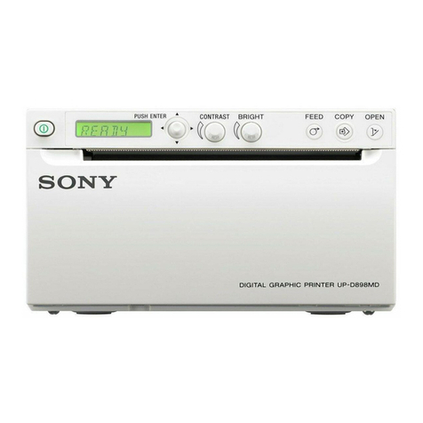
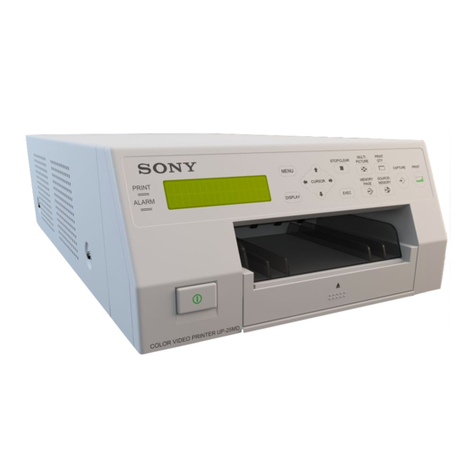
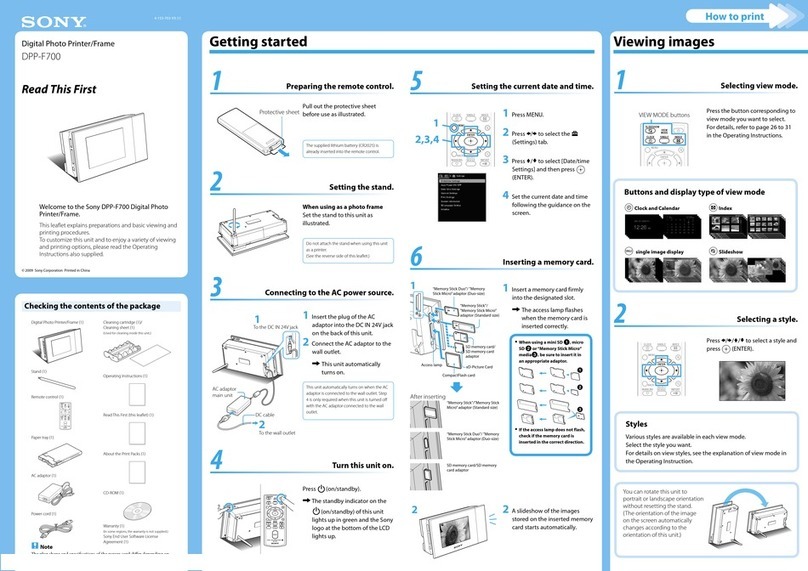
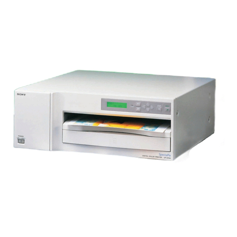
Sony OEP-4 User manual

COLOR VIDEO PRINTER
OEP-4
SERVICE MANUAL
Volume 1 1st Edition

OEP-4
!WARNING
This manual is intended for qualified service personnel only.
To reduce the risk of electric shock, fire or injury, do not perform any servicing other than that
contained in the operating instructions unless you are qualified to do so. Refer all servicing to
qualified service personnel.
!WARNUNG
Die Anleitung ist nur für qualifiziertes Fachpersonal bestimmt.
Alle Wartungsarbeiten dürfen nur von qualifiziertem Fachpersonal ausgeführt werden. Um die
Gefahr eines elektrischen Schlages, Feuergefahr und Verletzungen zu vermeiden, sind bei
Wartungsarbeiten strikt die Angaben in der Anleitung zu befolgen.Andere als die angegeben
Wartungsarbeiten dürfen nur von Personen ausgeführt werden, die eine spezielle Befähigung
dazu besitzen.
!AVERTISSEMENT
Ce manual est destiné uniquement aux personnes compétentes en charge de l’entretien.Afin
de réduire les risques de décharge électrique, d’incendie ou de blessure n’effectuer que les
réparations indiquées dans le mode d’emploi à moins d’être qualifié pour en effectuer d’autres.
Pour toute réparation faire appel à une personne compétente uniquement.

1
OEP-4
Table of Contents
Manual Structure
Purpose of this manual ................................................................. 3
Related manuals ........................................................................... 3
Trademarks ................................................................................... 3
1. Service Overview
1-1. Board Location ...............................................................1-1
1-2. Main Parts Location........................................................1-1
1-3. Removing/Installing the Cabinet ....................................1-2
1-3-1. Top Cover..............................................................1-2
1-3-2. Front Panel Assembly ...........................................1-2
1-3-3. Rear Panel Assembly ............................................1-2
1-4. Replacing the Board .......................................................1-3
1-4-1. MA-142G Board ...................................................1-3
1-4-2. MEC-24G Board ...................................................1-3
1-4-3. KY-582G Board/DP-407G Board/
SE-756 Board ........................................................1-4
1-4-4. SE-747 Board/SE-750 Board/SE-752 Board ........1-5
1-4-5. IF-990G Board/IF-989G Board.............................1-6
1-4-6. IF-988G Board ......................................................1-6
1-5. Replacing the Main Parts ................................................1-7
1-5-1. Switching Regulator ..............................................1-7
1-5-2. Mechanical Main Unit Assembly..........................1-7
1-5-3. Stepping Motor......................................................1-8
1-5-4. Ribbon Drive Assembly ......................................1-10
1-5-5. Center Stay Assembly .........................................1-11
1-5-6. Paper Feed Guide Assembly ...............................1-12
1-5-7. DC Fan (Head Unit) ............................................1-13
1-5-8. Thermal Head ......................................................1-13
1-5-9. Pinch Roller .........................................................1-14
1-5-10. Capstan Roller/Platen Roller ...............................1-15
1-5-11. Cam Gear (L)/Cam Gear (R)...............................1-16
1-5-12. Interlock Switch ..................................................1-19
1-6. Unleaded Solder............................................................1-19
2. Electrical Alignment
2-1. Service Mode ..................................................................2-1
2-1-1. Startup Procedure ..................................................2-1
2-2. Adjustment Menu ...........................................................2-1
2-2-1. Button Operation in Menu.....................................2-1
2-2-2. Description of Each Menu.....................................2-1
2-3. Thermal Head Replacement Procedure ..........................2-4
2-3-1. Test Pattern Print ...................................................2-4
2-3-2. Density Check and Adjustment .............................2-5
2-3-3. Printing Position Check and Adjustment ..............2-5
2-3-4. Head Total Count Reset ........................................2-5
2-4. Master Reset (Initialization) ...........................................2-5
2-5. Version Upgrade .............................................................2-6
2-5-1. Version Upgrade ...................................................2-6
2-5-2. Restoration of This Unit ........................................2-7
3. Troubleshooting
3-1. MECHA JIGU MODE ...................................................3-1
3-1-1. Startup Procedure ..................................................3-1
3-1-2. Button Operation in Menu.....................................3-1
3-1-3. Menu Description ..................................................3-1
3-2. Saving Function to Memory Stick ..................................3-2
3-3. Error Code Table ............................................................3-3
3-4. Operating Mode (Status).................................................3-5
3-5. Troubleshooting ..............................................................3-5
4. Location and Functions of Sensors,
Motors, and Mechanical Parts
4-1. Sensors and Motors.........................................................4-2
4-2. Mechanical Parts.............................................................4-2

2OEP-4
5. Circuit Description
5-1. Outline of Operation .......................................................5-1
5-2. Outline of MA-142G Board............................................5-1
5-2-1. Video Signal Processing Block .............................5-1
5-2-2. System Control, Mechanism, and
Print Control Block ...............................................5-3
5-2-3. SOC (IC103) Block ...............................................5-3
5-2-4. Printer-Dedicated Circuit (IC301).........................5-5
5-2-5. Mechanical Control Block ....................................5-8
5-2-6. Head Control Block...............................................5-8
5-2-7. IC-TAG Control Block..........................................5-8
5-2-8. Key Input and Liquid-Crystal
Display Control Block...........................................5-9
5-2-9. Fan Control............................................................5-9
5-2-10. Power Circuit Block ..............................................5-9
5-3. Outline of KY-582G Board ............................................5-9
5-4. Outline of DP-407G Board .............................................5-9
5-5. Mechanical Control Block ............................................5-10
5-5-1. Outline of Motor Driving Function Blocks .........5-10
5-5-2. Sensor Detection Circuits ....................................5-13

3
OEP-4
Purpose of this manual This manual is the service manual Vol. 1 of Color Video Printer OEP-4.
This manual describes the information on maintenance and the service information
such as service overview, electrical alignment, troubleshooting, and location and
functions of sensors, motors, and mechanical parts.
Related manuals In addition to this “Service Manual Vol. 1”, this unit is provided with the manual
below.
..
..
.Service Manual Vol. 2 (Not supplied for products.)
Part No.: 9-879-991-1X
This manual describes the spare parts, block diagrams, schematic diagrams, and
board layouts of this unit.
..
..
.Operating Instruction (Supplied for products.)
Part No.: 2-638-113-1X
These manuals describes the information required for the actual management and
operation of this unit.
..
..
.“Semiconductor Pin Assignments” CD-ROM (Available on request)
This “Semiconductor Pin Assignments” CD-ROM allows you to search for
semiconductors used in Broadcast and Professional equipment.
Part number: 9-968-546-XX
Trademarks Trademarks and registered trademarks used in this manual are follows.
.Memory Stick is a registered trademark of SONY Corporation.
Other system names, product names, and company names appearing in this manual
are trademarks or registered trademarks of their respective holders.
Manual Structure


1-1
OEP-4
Section 1
Service Overview
Switching regulator
Thermal head
Mechanical main unit assembly DC fans (Head unit)
DC fan (For inside)
Stepping motor
DC motors (Head)
DC motors (Ribbon)
Ribbon drive assembly
SW-1200 board IF-990G board
IF-989G board
MA-142G board
SE-746 board
SE-756 board
EX-970 board
SE-762 board
SE-752 board
SE-751 board
SE-747 board
MEC-24G board
KY-582G board
DP-407G board
SE-755 board
CCM-53G board
SU-86 board
SU-84 board
SU-85 board
SU-87 board
SE-748 board
SE-754 board
SE-750 board
SE-753 board
SE-749 board
IF-988G board
1-1. Board Location
1-2. Main Parts Location

1-2 OEP-4
Top cover
M3 case securing
screws
M3 case
securing
screws
PSW3 x6
BVTT
2.6 x5
CN805
CN601 CN602
B M2.5
EG GRIP
Hook
Hooks Hook
MA-142G board
Harness
Flexible flat cables
Front panel assembly
IF-990G board
IF-989G
board
MA-142G
board BVTT
2.6 x5
BVTT
2.6 x5
CN201
CN108
AC inlet
Rear panel
assembly
Harnesses
Flexible flat cables
1-3. Removing/Installing the Cabinet
1-3-1. Top Cover
1. Remove the four M3 case securing screws and the
screw (PSW3 x6), then remove the top cover.
2. Attach the top cover in the reverse order.
1-3-2. Front Panel Assembly
1. Remove the top cover. (Refer to Section 1-3-1.)
2. Remove the three screws (BVTT2.6 x5) and the
screw (B M2.5 EG GRIP).
3. Disconnect the harness and two flexible flat cables
from the connectors (CN805, CN601 and CN602) on
the MA-142G board.
4. Remove the four hooks, then remove the front panel
assembly.
5. Attach the front panel assembly in the reverse order of
steps 1 to 4.
1-3-3. Rear Panel Assembly
1. Remove the top cover. (Refer to Section 1-3-1.)
2. Remove the four screws, then remove the rear panel
assembly.
3. Disconnect the flexible flat cable from the connector
(CN201) on the IF-990G board.
4. Disconnect the flexible flat cable from the connector
(CN108) on the IF-989G board.
5. Disconnect the three harnesses from the AC inlet of
the rear panel assembly.
6. Attach the rear panel assembly in the reverse order of
steps 1 to 5.

1-3
OEP-4
BVTT
2.6 x5
MA-142G
board
Core holder (L)Ferrite bead
CN805
CN601
CN803
CN802
CN801
CN602
CN202 CN804
CN1001
CN1901
CN201
CN1458 CN301
CN203
CN904
MA-142G board (Side A)
Flexible flat cables
Flexible flat
cables
Harnesses
Harnesses
Harness
W2.3
Flexible flat
cables
Harnesses
Harnesses
Harnesses
MEC-24G board (Side A)
BVTT
2.6 x5
MEC-24G board
CN203 CN110 CN201 CN202
CN101
CN104
CN106
CN105
CN107
CN204
CN103
1-4. Replacing the Board
1-4-1. MA-142G Board
n
After replacing the MA-142G board or IC910 on the MA-
142G board, perform the CPU version upgrade.
For procedure, refer to Section 2-5.
1. Remove the top cover. (Refer to Section 1-3-1.)
2. Disconnect the six harnesses from the connectors
(CN201, CN202, CN203, CN804, CN805 and 1901)
on the MA-142G board.
3. Disconnect the nine flexible flat cables from the connectors
(CN301, CN601, CN602, CN801, CN802, CN803,
CN904, 1001 and 1458) on the MA-142G board.
4. Remove the six screws (BVTT2.6 x5), then remove
the MA-142G board.
5. Remove the ferrite bead and core holder (L) on the
MA-142G board.
6. Install the MA-142G board in the reverse order of
steps 1 to 5.
1-4-2. MEC-24G Board
1. Remove the top cover. (Refer to Section 1-3-1.)
2. Remove the front panel assembly.
(Refer to Section 1-3-2.)
3. Remove the rear panel assembly.
(Refer to Section 1-3-3.)
4. Remove the switching regulator.
(Refer to Section 1-5-1.)
5. Remove the mechanical main unit assembly.
(Refer to Section 1-5-2.)
6. Disconnect the nine harnesses from the connectors
(CN103 to CN107, CN110, CN201, CN203 and
CN204) and two flexible flat cables from the connectors
(CN101 and CN202) on the MEC-24G board.
7. Remove the four screws and the retaining ring, then
remove the MEC-24G board.
8. Install the MEC-24G board in the reverse order of
steps 1 to 7.

1-4 OEP-4
PSW
2.6 x8
BVTT
2 x10
BVTP2.6 x6
PSW
2.6 x8
SE-756
board
Protection
plate
Spring (B)
SW mounting
plate
Ribbon door assembly
Front panel
Switch plate
Harness
M2 x5
BVTP
2.6 x6
BVTP
2.6 x6
BVTP
2.6 x6
BVTP
2.6 x6
CN501
CN401
KY-582G
board
DP-407G
board
Ribbon door
assembly
Door cover
assembly
Reinforcing
plate (door)
Flexible flat
cable
Flexible flat
cable
Hooks
Hook
Spring
(KEY)
Spring
(LCD)
1-4-3. KY-582G Board/DP-407G Board/SE-
756 Board
1. Remove the top cover. (Refer to Section 1-3-1.)
2. Remove the front panel assembly.
(Refer to Section 1-3-2.)
3. Remove the screw (BVTP2.6 x6), then remove the
SW mounting plate.
4. Remove the screw (BVTT2 x10), then remove the
SE-756 board and switch plate.
5. Disconnect the harness from the connector on the SE-
756 board.
6. Remove the two screws (PSW2.6 x8), protection
plate and spring (B), then remove the ribbon door
assembly.
7. Remove the three screws (M2 x5) and six hooks of
the ribbon door assembly, then remove the door cover
assembly.
8. Remove the six screws (BVTP2.6 x6), then remove
the reinforcing plate (door).
9. Remove the nine screws (BVTP2.6 x6), then remove
the spring (KEY) and KY-582G board.
10. Disconnect the flexible flat cable from the connector
(CN501) on the KY-582G board.
11. Remove the two screws (BVTP2.6 x6), then remove
the spring (LCD) and DP-407G board.
12. Disconnect the flexible flat cable from the connector
(CN407) on the DP-407G board.
13. Install the KY-582G board, DP-407G board and SE-
756 board in the reverse order of steps 1 to 12.

1-5
OEP-4
A
B
E
D
C
SE-752
board
Harness
Harness
Harness
BVTT
2.6 x5
Ribbon sensor (R) cover
Hooks [A]
Hook [D]
Hook [D]
Projection
Paper center
guide
Center stay
SE-747 board
SE-750 board
Hook [C]
Hook [B]
SE-747 board
SE-750 board
BTP
2.6 x6
1-4-4. SE-747 Board/SE-750 Board/SE-752
Board
1. Remove the top cover. (Refer to Section 1-3-1.)
2. Remove the front panel assembly.
(Refer to Section 1-3-2.)
3. Remove the MA-142G board. (Refer to Section 1-4-1.)
4. Remove the mechanical main unit assembly.
(Refer to Section 1-5-2.)
5. Remove the MEC-24G board.
(Refer to Section 1-4-2.)
6. Remove the stepping motor. (Refer to Section 1-5-3.)
7. Remove the ribbon drive assembly.
(Refer to Section 1-5-4.)
8. Remove the center stay assembly.
(Refer to Section 1-5-5.)
9. Remove the screw (BVTT2.6 x5) and disconnect the
harness from the connector on the SE-752 board, then
remove the SE-752 board.
10. Remove the two hooks [A], then remove the ribbon
sensor (R) cover.
11. Remove the two screws (BTP2.6 x6) and two hooks
[D] while pushing the projection of paper center guide,
then remove the center stay in the direction of the
arrow E.
12. Remove the hook [B] in the direction of the arrow A,
then remove the SE-747 board in the direction of the
arrow B.
13. Disconnect the harness from the connector on the SE-
747 board.
14. Remove the hook [C] in the direction of the arrow C,
then remove the SE-750 board in the direction of the
arrow D.
15. Disconnect the harness from the connector on the SE-
750 board.
16. Install the SE-747 board, SE-750 board and SE-752
board in the reverse order of steps 1 to 15.

1-6 OEP-4
Memory
Stick
IF-988G board
CN301
BVTT
2.6 x5
BVTT
2.6 x5
MS bracket
Flexible flat
cable
IF-990G
board
IF-989G board
CN108
CN201
BVTP
3 x8
BVTP
3 x8
BVTT
2.6 x5
BVTT
2.6 x5
Remote bracket
Connector screws
Flexible flat cable
Flexible flat
cable
1-4-6. IF-988G Board
1. Remove the top cover. (Refer to Section 1-3-1.)
2. Remove the front panel assembly.
(Refer to Section 1-3-2.)
3. Remove the MA-142G board. (Refer to Section 1-4-1.)
4. Remove the chassis stay.
(Refer to step 4 in Section 1-5-2.)
5. Remove the Memory Stick from the IF-988G board.
6. Remove the three screws, then remove the MS bracket
in the direction of the arrow.
7. Disconnect the flexible flat cable from the connector
(CN301) on the IF-988G board.
8. Remove the four screws, then remove the IF-988G
board.
9. Install the IF-988G board in the reverse order of steps
1 to 8.
1-4-5. IF-990G Board/IF-989G Board
1. Remove the top cover. (Refer to Section 1-3-1.)
2. Remove the front panel assembly.
(Refer to Section 1-3-2.)
3. Remove the rear panel assembly.
(Refer to Section 1-3-3.)
4. Remove the two screws (BVTT2.6 x5), then remove
the remote bracket.
5. Disconnect the flexible flat cable from the connector
(CN201) on the IF-990G board.
6. Remove the two screws (BVTT2.6 x5) and two
connector screws, then remove the IF-990G board.
7. Disconnect the flexible flat cable from the connector
(CN108) on the IF-989G board.
8. Remove the ten screws (BVTP3 x8), then remove the
IF-989G board.
9. Install the IF-990G and IF-989G boards in the reverse
order of steps 1 to 8.

1-7
OEP-4
PS3 x6
PS3 x6
PS3 x6
PS
3 x6
90 mm or more
Required driver
Shield plate (A)
Protector
sheet (A)
Switching
regulator
Harness
Harnesses
BVTT
2.6 x5
BVTT
2.6 x5
BVTT
2.6 x5
BVTT
2.6 x5
Chassis stay Top stay (R)
1-5. Replacing the Main Parts
1-5-1. Switching Regulator
1. Remove the top cover. (Refer to Section 1-3-1.)
2. Remove the front panel assembly.
(Refer to Section 1-3-2.)
3. Remove the rear panel assembly.
(Refer to Section 1-3-3.)
4. Remove the MA-142G board. (Refer to Section 1-4-1.)
5. Remove the two screws, then remove the shield plate
(A) and protector sheet (A).
6. Disconnect the three harnesses from the connectors on
the switching regulator.
7. Remove the four screws, then remove the switching
regulator.
8. Attach the switching regulator in the reverse order of
steps 1 to 7.
1-5-2. Mechanical Main Unit Assembly
1. Remove the top cover. (Refer to Section 1-3-1.)
2. Remove the front panel assembly.
(Refer to Section 1-3-2.)
3. Remove the MA-142G board. (Refer to Section 1-4-1.)
4. Remove the four screws, then remove the chassis stay.
5. Remove the four screws, then remove the top stay (R).

1-8 OEP-4
BVTT
2.6 x5
BVTT
2.6 x5
BVTT2.6 x5 BVTT2.6 x5
BVTT
2.6 x5
BVTT
2.6 x5
BVTT
2.6 x5
MA shield plate
Mechanical
main unit
assembly
Harnesses
Bottom
stay (L)
Bottom
stay (R)
Switching
regulator
W2.3
W2.3
Pick-up belt
Sensor gear
Tension arm (S) subassembly
Helical extension
spring
Helical extension
spring
Pick-up belt gear
Tension arm
assembly
6. Remove the four screws, then remove the MA shield
plate.
7. Disconnect the two harnesses from the switching
regulator.
8. Remove the six screws, then remove the mechanical
main unit assembly.
9. Remove the four screws, then remove the bottom stay
(L) and bottom stay (R).
10. Attach the mechanical main unit assembly in the
reverse order of steps 1 to 9.
1-5-3. Stepping Motor
Removal
1. Remove the top cover. (Refer to Section 1-3-1.)
2. Remove the front panel assembly.
(Refer to Section 1-3-2.)
3. Remove the MA-142G board. (Refer to Section 1-4-1.)
4. Remove the mechanical main unit assembly.
(Refer to Section 1-5-2.)
5. Remove the MEC-24G board.
(Refer to Section 1-4-2.)
6. Remove the retaining ring, then remove the sensor
gear.
7. Remove the helical extension spring from the tension
arm assembly.
8. Remove the helical extension spring from the tension
arm (S) subassembly.
9. Remove the retaining ring, then remove the pick-up
belt gear and pick-up belt.

1-9
OEP-4
E4.0
PS3 x4
BVTT
2.6 x5
BVTT
2.6 x5 Stepping motor belt
Capstan belt
Stepping motor Stepping motor bracket
Capstan pulley
W2.3
Sensor gear
Stepping motor belt
Pick-up belt
Capstan belt
Stepping motor
Sensor gear
Cam gear (L)
Shaft
Oblong hole
Oblong hole of
chassis Hole of cam
gear (L)
Visually align the
position of holes.
50 mm or more
ø2
Shaft
10. Remove the retaining ring, then remove the capstan
pulley and parallel pin.
11. Remove the four screws (BVTT2.6 x5), then remove
the stepping motor bracket.
12. Remove the two screws (PS3 x4), then remove the
stepping motor, stepping motor belt and capstan belt.
Installation
13. Attach the stepping motor in the reverse order of steps
7 to 12.
14. Insert the shaft (ø2, length: 50 mm or more) from the
oblong hole of the sensor gear, or visually align the
oblong holes of the sensor gear and chassis, and the
hole of cam gear (L).
15. Attach the retaining ring to the sensor gear.
16. Assemble this unit in the reverse order of steps 1 to 5.

1-10 OEP-4
Mechanical main
unit assembly
BVTT
2.6 x5
BVTT
2.6 x5
Ribbon drive assembly
SU-87 board
Harnesses
SU-86 board
PS3 x4
Ribbon lock
Ribbon lock
Ribbon lock
spring
Supply
lock
Supply lock
Supply lock
spring
W2.3
W2.3
W2.3
W3
W3
W2.3
Ribbon gear
Ribbon gear
Idler gear (R)
Idler gear (R)
Worm wheel (R)
Worm wheel (R)
Limiter (S)
assembly
Limiter (T)
assembly
Limiter (S) assembly
Limiter (T)
assembly
DC motor (ribbon)
subassemblies
DC motor (ribbon) subassemblies
1-5-4. Ribbon Drive Assembly
1. Remove the top cover. (Refer to Section 1-3-1.)
2. Remove the front panel assembly.
(Refer to Section 1-3-2.)
3. Remove the MA-142G board. (Refer to Section 1-4-1.)
4. Remove the mechanical main unit assembly.
(Refer to Section 1-5-2.)
5. Remove the four screws, then remove the ribbon drive
assembly.
6. Disconnect the two harnesses from the connectors on
the SU-86 board and SU-87 board.
7. Remove the two retaining rings (W2.3) and the
retaining ring (W3.0), then remove the idler gear (R),
worm wheel (R) and limiter (S) assembly.
8. Remove the four screws, then remove the two DC
motor (ribbon) subassemblies.
9. Remove the retaining ring (W2.3), then remove the
ribbon lock and ribbon lock spring.
10. Remove the retaining ring (W2.3), then remove the
supply lock and supply lock spring.
11. Remove the retaining ring (W3.0), then remove the
ribbon gear.
12. Remove the retaining ring (W2.3), then remove the
limiter (T) assembly.
13. Attach the ribbon drive assembly in the reverse order
of steps 1 to 12.

1-11
OEP-4
A
B
C
D
EFG
AC
D
EFG
HI
J
KLM
N
H
I
J
K
L
M
N
B
Portion A
Portion B
BVTT
2.6 x5
BVTT
2.6 x5
Front corner stay
Ribbon rail (L)
Ribbon rail (R)
CCM-53G board
BVTT
2.6 x5
BVTT
2.6 x5
Center stay assembly
Harnesses
Hole
Shaft of pendulum arm
1-5-5. Center Stay Assembly
n
When removing the center stay, be careful not to damage
the harness.
1. Remove the top cover. (Refer to Section 1-3-1.)
2. Remove the front panel assembly.
(Refer to Section 1-3-2.)
3. Remove the MA-142G board. (Refer to Section 1-4-1.)
4. Remove the mechanical main unit assembly.
(Refer to Section 1-5-2.)
5. Remove the MEC-24G board.
(Refer to Section 1-4-2.)
6. Remove the stepping motor. (Refer to Section 1-5-3.)
7. Remove the four screws, then remove the front corner
stay.
8. Remove the seven hooks (A to G) while pushing the
portion A of the ribbon rail (L) from outside of the
main chassis, then remove the ribbon rail (L) in the
direction shown by the arrow.
9. Remove the two screws, then remove the CCM-53G
board.
10. Remove the seven hooks (H to N) while pushing the
portion B of the ribbon rail (R) from outside of the
main chassis, then remove the ribbon rail (R) in the
direction shown by the arrow.
11. Remove the three screws, then remove the center stay
assembly.
12. Attach the center stay assembly in the reverse order of
steps 1 to 11.
n
Be sure to securely attach the shaft of the pendulum
arm to the hole of the center stay assembly.

1-12 OEP-4
W3.0
W3.0
Pick-up gear
Bearing (850)
Helical
extension
spring
Helical extension
spring
BVTT
2.6 x5
Pick-up arm (L) subassembly
Pick-up arm (R)
subassembly
Bearing
(850)
Tray rail (L)
Tray rail (R)
A
B
Pick-up roller
Main chassis
Paper feed guide assembly
Harness
BVTT
2.6 x5
Portions A
Portions B
1-5-6. Paper Feed Guide Assembly
n
When removing the paper feed guide assembly, be careful
not to damage the harness.
1. Remove the top cover. (Refer to Section 1-3-1.)
2. Remove the front panel assembly.
(Refer to Section 1-3-2.)
3. Remove the MA-142G board. (Refer to Section 1-4-1.)
4. Remove the mechanical main unit assembly.
(Refer to Section 1-5-2.)
5. Remove the MEC-24G board.
(Refer to Section 1-4-2.)
6. Remove the stepping motor. (Refer to Section 1-5-3.)
7. Remove the ribbon drive assembly.
(Refer to Section 1-5-4.)
8. Remove the center stay assembly.
(Refer to Section 1-5-5.)
9. Remove the retaining ring, then remove the pick-up
gear and bearing (850).
10. Remove the retaining ring, then remove the bearing
(850).
11. Remove the two helical extension springs from the
pick-up arm (L) subassembly and pick-up arm (R)
subassembly.
12. Remove the two screws, then remove the tray rail (L)
and tray rail (R).
13. Remove the pick-up roller in the directions shown by
the arrows A and B.
14. Remove the two screws, then remove the paper feed
guide assembly.
15. Attach the paper feed guide assembly in the reverse
order of steps 1 to 14.
n
When attaching the paper feed guide assembly, be sure
to securely insert the portions A of the paper feed
guide assembly into the portions B of the main chassis.

1-13
OEP-4
BVTT
2.6 x5
BVTT
3 x14
Rear corner stay
DC fans
CN303 EX-970 board
CN302
Fan mounting plate
Harnesses BVTT
2.6 x5
Mechanical main
unit assembly
1-5-7. DC Fan (Head Unit)
1. Remove the top cover. (Refer to Section 1-3-1.)
2. Remove the front panel assembly.
(Refer to Section 1-3-2.)
3. Remove the MA-142G board. (Refer to Section 1-4-1.)
4. Remove the mechanical main unit assembly.
(Refer to Section 1-5-2.)
5. Remove the two screws (BVTT2.6 x5), then remove
the rear corner stay.
6. Remove the two screws (BVTT2.6 x5), then remove
the fan mounting plate.
7. Disconnect the two harnesses from the connectors
(CN302 and CN303) on the EX-970 board.
8. Remove the four screws (BVTT3 x14), then remove
the two DC fans.
9. Attach the two DC fans in the reverse order of steps 1
to 8.
1-5-8. Thermal Head
n
After replacing the thermal head, the adjustment is required.
Be sure to print a sample as a reference before replacing
the thermal head. For details, refer to Section 2-3.
1. Remove the top cover. (Refer to Section 1-3-1.)
2. Remove the front panel assembly.
(Refer to Section 1-3-2.)
3. Remove the MA-142G board. (Refer to Section 1-4-1.)
4. Remove the top chassis stay, top stay (R) and MA
shield plate. (Refer to steps 4 to 6 in Section 1-5-2.)
5. Remove the two screws (BVTT2.6 x5), then remove
the top stay.
6. Remove the screw (PSW2.6 x5), then remove the
ribbon sensor mounting plate.
7. Disconnect the harness from the thermal head.
8. Remove the two precision screws (P2.6 x5) and two
screws (PSW2.6 x12), then ribbon guide (T) and two
eccentric pins.
n
At that time, hold the head with your hand so that it
does not drop off.
9. Slightly pull out the thermal head, and then disconnect
the flexible flat cable.
BVTT
2.6 x5
PSW
2.6 x12 PSW
2.6 x5
Top stay
Ribbon guide (T)
Ribbon sensor
mounting plate
Harness
Thermal
head
Flexible
flat cable
Eccentric
pins
Precision
screws
P2.6 x5

1-14 OEP-4
E2.3
E3.0
E3.0
E2.3
Pinch roller
Pinch roller assembly
Bearing flange
Bearing flange
Bearing
Bearing
Helical
extension
spring
Helical
extension
spring
1-5-9. Pinch Roller
1. Remove the top cover. (Refer to Section 1-3-1.)
2. Remove the front panel assembly.
(Refer to Section 1-3-2.)
3. Remove the MA-142G board. (Refer to Section 1-4-1.)
4. Remove the mechanical main unit assembly.
(Refer to Section 1-5-2.)
5. Remove the MEC-24G board.
(Refer to Section 1-4-2.)
6. Remove the stepping motor. (Refer to Section 1-5-3.)
7. Remove the ribbon drive assembly.
(Refer to Section 1-5-4.)
8. Remove the center stay assembly.
(Refer to Section 1-5-5.)
9. Remove the paper feed guide assembly.
(Refer to Section 1-5-6.)
10. Remove the two retaining rings (E3.0) and two helical
extension springs, then remove the pinch roller
assembly.
11. Remove the two retaining rings (E2.3), two bearing
flanges and two bearings, then remove the pinch roller.
12. Attach the pinch roller in the reverse order of steps 10
and 11.
13. Clean the pinch roller with alcohol.
14. Assemble this unit in the reverse order of steps 1 to 9.
10. Attach the thermal head in the reverse order of steps 1
to 9.
n
.Check that the eccentric pin is inserted in the hole of
thermal head.
(If not, the eccentric pin floats.)
.Insert the projection of ribbon guide (T) into the
groove of eccentric pin, and then position the ribbon
guide (T) using the dowel and secure it with the two
screws.
PSW
2.6 x12
Thermal head
Heat sink
Ribbon guide (T)
Ribbon guide (T)
Dowels
Eccentric pins
Eccentric
pin
Groove Groove
Projection Projection
Eccentric
pin
Hole
Hole
Default position
of eccentric pin
Front side
Other manuals for OEP-4
1
Table of contents
Other Sony Printer manuals

Sony
Sony UP-970AD User manual

Sony
Sony UP-991AD User manual

Sony
Sony UPA-PC105 User manual

Sony
Sony UP-CR25L User manual

Sony
Sony UP-970AD User manual

Sony
Sony UP-D71XR User manual

Sony
Sony UP-897MD User manual

Sony
Sony DSC-T70HDPR User manual

Sony
Sony DPP-MS300 Marketing User manual

Sony
Sony UP-DR80MD User manual

Sony
Sony DPP-M55 Marketing User manual

Sony
Sony UPX-DP10 User manual

Sony
Sony UP-DR150 User manual

Sony
Sony DPP-F700 - Digital Photo Printer/frame Manual

Sony
Sony UP-D2600 User manual

Sony
Sony DPP-FPHD1 Instruction Manual (Photo Printer) User manual

Sony
Sony UP-910 User manual

Sony
Sony DPP-MP1 User manual

Sony
Sony DPP-EX50 User manual

Sony
Sony UP-CX2 User manual