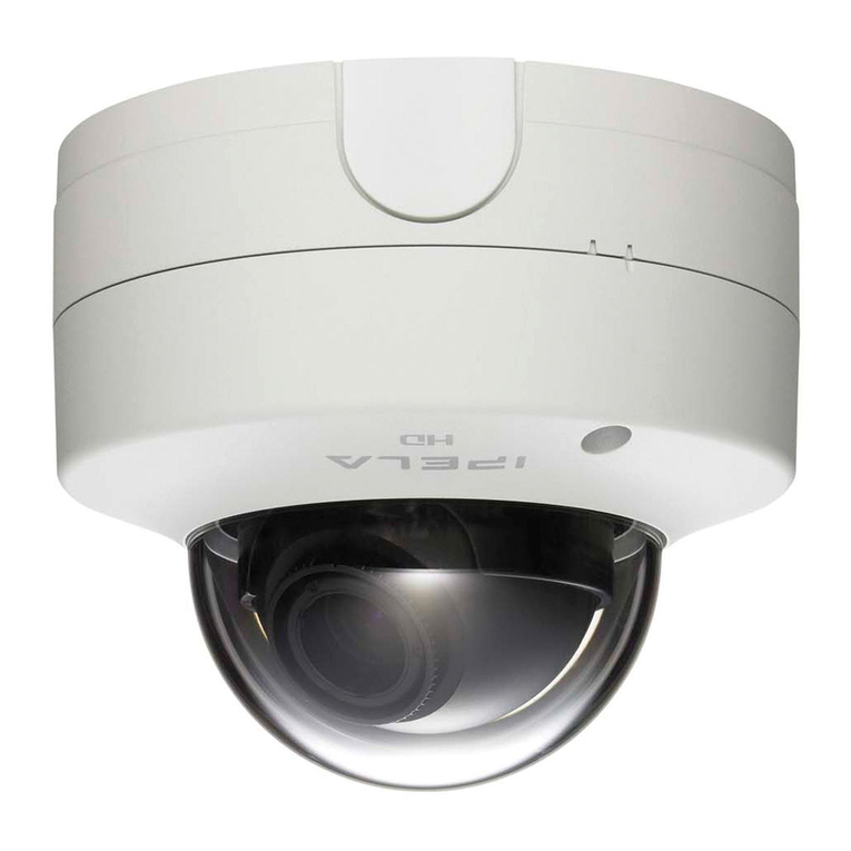
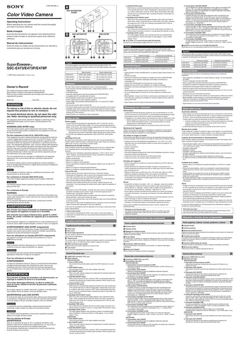
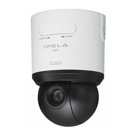
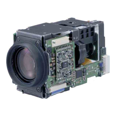
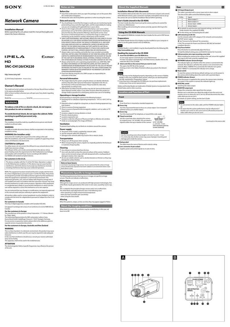
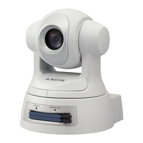
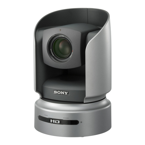
Sony SNC-CS11 - IPELA Network Camera User manual

NETWORK CAMERA
SNC-CS11
SNC-CS10
SERVICE MANUAL
1st Edition

SNC-CS10/CS11
!WARNING
This manual is intended for qualified service personnel only.
To reduce the risk of electric shock, fire or injury, do not perform any servicing other than that
contained in the operating instructions unless you are qualified to do so. Refer all servicing to
qualified service personnel.
!WARNUNG
Die Anleitung ist nur für qualifiziertes Fachpersonal bestimmt.
Alle Wartungsarbeiten dürfen nur von qualifiziertem Fachpersonal ausgeführt werden. Um die
Gefahr eines elektrischen Schlages, Feuergefahr und Verletzungen zu vermeiden, sind bei
Wartungsarbeiten strikt die Angaben in der Anleitung zu befolgen.Andere als die angegeben
Wartungsarbeiten dürfen nur von Personen ausgeführt werden, die eine spezielle Befähigung
dazu besitzen.
!AVERTISSEMENT
Ce manual est destiné uniquement aux personnes compétentes en charge de l’entretien.Afin
de réduire les risques de décharge électrique, d’incendie ou de blessure n’effectuer que les
réparations indiquées dans le mode d’emploi à moins d’être qualifié pour en effectuer d’autres.
Pour toute réparation faire appel à une personne compétente uniquement.
WARNING
This unit has no power switch.
When installing the unit, incorporate a readily
accessible disconnect device in the fixed wiring, so that
the user can turn off the power in case a fault should
occur.
WARNUNG
Dieses Gerät hat keinen Netzschalter.
Beim Einbau des Geräts ist daher im Festkabel ein leicht
zugänglicher Unterbrecher einzufügen, damit sich bei
einer Funktionsstörung die Stromversorgung zum Gerät
jederzeit unterbrechen lä
ß
t.
When using a modular jack cable:
For safety, do not connect to the connector for peripheral
device wiring that might have excessive voltage.

1
SNC-CS10/CS11
Table of Contents
Manual Structure
Purpose of this manual ................................................................. 3
Related manuals ........................................................................... 3
Trademarks ................................................................................... 3
1. Service Overview
1-1. Board Location ...............................................................1-1
1-2. Unleaded Solder..............................................................1-1
1-3. Removing/Installing the Lens.........................................1-1
1-4. Removing/Installing the Cabinet ....................................1-2
1-4-1. Upper Case Assembly ...........................................1-2
1-4-2. Rear Assembly ......................................................1-2
1-4-3. Front Assembly .....................................................1-2
1-5. Removing/Installing the Board .......................................1-3
1-5-1. SY-339 Board........................................................1-3
1-5-2. PR-297 Board ........................................................1-3
1-5-3. PS-720 Board ........................................................1-4
1-5-4. CN-2861 Board .....................................................1-4
1-6. Replacing the Optical Filter Block .................................1-5
1-7. Replacing the Electrolytic Capacitor ..............................1-5
2. Adjustment
2-1. Preparation ......................................................................2-1
2-1-1. Required Equipment..............................................2-1
2-1-2. Connection Diagram .............................................2-2
2-1-3. Starting a PR Board Adjustment Software............2-3
2-2. Adjustment......................................................................2-3
2-2-1. Initialization of EEPROM .....................................2-3
2-2-2. CCD Defect Correction .........................................2-3
2-2-3. White Balance Adjustment....................................2-5
2-2-4. Color Reproduction Adjustment ...........................2-6
2-2-5. Procedure after Completion of Overall
Adjustment ............................................................2-6
2-3. Check of SY-339 Board..................................................2-7
2-3-1. Starting an SY Board Check Software ..................2-7
2-3-2. LED Operation Check ...........................................2-8
2-3-3. Sensor Operation Check ........................................2-8
2-3-4. Alarm OUT Operation Check ...............................2-9
2-3-5. Audio IN/OUT Operation Check ..........................2-9
2-3-6. Auto Iris Lens Check...........................................2-10
2-3-7. Procedure after Operation Check ........................2-10
2-4. RTC Adjustment ...........................................................2-11
3. Circuit Description
3-1. Processing Block of Video and Audio Data ...................3-1
3-1-1. Processing Block of Video Data ...........................3-1
3-1-2. Processing Block of Audio Data ...........................3-1
3-2. Boards .............................................................................3-1
3-2-1. SE-849 Board ........................................................3-1
3-2-2. PR-297 Board ........................................................3-1
3-2-3. SY-339 Board........................................................3-2
3-2-4. CN-2861 Board .....................................................3-2
3-2-5. PS-720 Board ........................................................3-2
4. Semiconductor Pin Assignments
5. Spare Parts
5-1. Notes on Repair Parts .....................................................5-1
5-2. Exploded Views ..............................................................5-2
5-3. Electrical Parts List.........................................................5-4
5-4. Packing Materials & Supplied Accessories ..................5-10
6. Overall Block Diagrams
(including Frame Wiring)
Overall ............................................................................6-1
7. Schematic Diagrams
CN-2861 .........................................................................7-1
PR-297 ............................................................................7-2
PS-720.............................................................................7-3
SE-849 ............................................................................7-5
SY-339 ............................................................................7-6
8. Board Layouts
CN-2861 .........................................................................8-1
PR-297 ............................................................................8-2
SE-849 ............................................................................8-2
PS-720.............................................................................8-3
SY-339 ............................................................................8-4

3
SNC-CS10/CS11
Purpose of this manual This manual is the Service Manual of the Network Camera SNC-CS10/CS11.
This manual contains the service overview, adjustments, circuit description,
semiconductor pin assignments, spare parts, overall block diagrams (including frame
wiring), schematic diagrams, and board layouts.
Related manuals In addition to this Service Manual, the following manuals are provided.
..
..
.Installation Manual (Supplied with SNC-CS10/CS11)
Part number: 2-687-967-1X (English, French)
2-687-967-2X (German, Italian)
2-687-967-3X (Spanish, Chinese)
This manual describes the information on installing the SNC-CS10/CS11.
..
..
.“User’s Guide” CD-ROM (Supplied with SNC-CS10/CS11)
Part number: 2-687-965-0X
This manual describes the information required for the proper operation and
application of this unit.
..
..
.“Semiconductor Pin Assignments” CD-ROM (Available on request)
This “Semiconductor Pin Assignments” CD-ROM allows you to search for
semiconductors used in Broadcast and Professional equipment.
This manual contains a complete list of semiconductors and their ID Nos., and
thus should be used together with the CD-ROM.
Part number: 9-968-546-XX
Trademarks Trademarks and registered trademarks used in this manual are follows.
.Windows is a registered trademark of Microsoft Corporation
in the United States and other countries.
Other system names, product names, and company names appearing in this manual
are trademarks or registered trademarks of their respective holders.
Manual Structure


1-1
SNC-CS10/CS11
Section 1
Service Overview
1-1. Board Location
1-2. Unleaded Solder
Boards requiring use of unleaded solder are printed with a
lead free mark (LF) indicating the solder contains no lead.
(Caution: Some printed circuit boards may not come
printed with the lead free mark due to their particular size.)
: LEAD FREE MARK
m
.Be sure to use the unleaded solder for the printed circuit
board printed with the lead free mark.
.The unleaded solder melts at a temperature about 40 dC
higher than the ordinary solder, therefore, it is recom-
mended to use the soldering iron having a temperature
regulator.
.The ordinary soldering iron can be used but the iron tip
has to be applied to the solder joint for a slightly longer
time. The printed pattern (copper foil) may peel away if
the heated tip is applied for too long, so be careful.
1-3. Removing/Installing the Lens
1. When the supplied vari-focal lens (SNC-CS11) or the
auto iris lens (DC control type) is attached, disconnect
the lens cable from the lens terminal.
n
This is not required when the manual iris lens is
attached.
2. Remove the lens by rotating it in the direction of the
arrow.
3. Attach the lens in the reverse order of steps 1 and 2.
CN-2861 board
SY-339 board
PR-297 board
PS-720 board
SE-849 board
Lens terminal
Lens cable
Vari-focal lens

1-2 SNC-CS10/CS11
1-4. Removing/Installing the Cabinet
1-4-1. Upper Case Assembly
Removal
1. Remove the lens. (Refer to Section 1-3.)
2. Remove the seven screws, then remove the upper case
assembly.
Installation
3. Attach the upper case assembly.
4. Attach the three screws 1.
5. Attach the four screws 2.
1-4-2. Rear Assembly
1. Remove the lens. (Refer to Section 1-3.)
2. Remove the upper case assembly.
(Refer to Section 1-4-1.)
3. Remove the three screws.
4. Disconnect the harness from the connector (CN901)
on the CN-2861 board, then remove the rear assembly.
5. Attach the rear assembly in the reverse order of steps 1
to 4.
1-4-3. Front Assembly
1. Remove the lens. (Refer to Section 1-3.)
2. Remove the upper case assembly.
(Refer to Section 1-4-1.)
3. Remove the screw, then remove the harness (with lug
terminal) from the lower case assembly.
4. Remove the four screws.
5. Remove the dowel Aof the front chassis from the
hole Aof the SY-339 board, then remove the front
assembly in the direction of the arrow.
6. Disconnect the flexible flat cable from the connector
(CN101) on the SE-849 board.
7. Attach the front assembly in the reverse order of steps
1 to 6.
2BSW M2 x 5
1BSW M2 x 5
1BSW M2 x 5
2BSW M2 x 5
Upper case
assembly
BSW M2 x 5
CN901
BSW M2 x 5
Rear assembly
Harness
CN-2861 board
Flexible flat cable
Front chassis
Hole A
Dowel A
BSW
M2 x 5
BSW
M2 x 5
CN101
SE-849 board
SY-339 board
Lower case
assembly
Harness
(with lug terminal)
Front assembly
BSW M2 x 5

1-3
SNC-CS10/CS11
1-5. Removing/Installing the Board
1-5-1. SY-339 Board
n
When replacing the SY-339 board, replace the MAC
address label attached to the bottom of the rear panel with
the new one supplied with the SY-339 board.
Removal
1. Remove the lens. (Refer to Section 1-3.)
2. Remove the upper case assembly.
(Refer to Section 1-4-1.)
3. Remove the four screws.
4. Disconnect the flexible flat cable from the connector
(CN503) and the two harnesses from the connectors
(CN403 and CN404) on the SY-339 board, then
remove the SY-339 board.
Installation
5. Connect the flexible flat cable to the connector
(CN503) and the two harnesses to the connectors
(CN403 and CN404) on the SY-339 board.
6. Insert the two projections Aof the PR-297 board into
the two holes Aof the SY-339 board.
7. Install the SY-339 board, then align the dowel Bof
the front chassis with the hole Bof the SY-339 board.
8. Attach the four screws in the order of 1, 2, 3and 4.
9. Assemble this unit in the reverse order of steps 1 and 2.
1-5-2. PR-297 Board
Removal
1. Remove the lens. (Refer to Section 1-3.)
2. Remove the upper case assembly.
(Refer to Section 1-4-1.)
3. Remove the rear assembly. (Refer to Section 1-4-2.)
4. Remove the SY-339 board. (Refer to Section 1-5-1.)
5. Disconnect the harness from the connector (CN203)
on the PR-297 board.
6. Remove the two screws, then remove the PR-297 board.
7. Disconnect the two flexible flat cables from the
connectors (CN205 and CN206) on the PR-297 board.
Installation
8. Connect the two flexible flat cables to the connectors
(CN205 and CN206) on the PR-297 board.
9. Insert the projection of the PR-297 board into the hole
of the PS-720 board.
10. Install the PR-297 board, then align the dowel Aof the
lower chassis with the hole Aof the PR-297 board.
11. Attach the two screws in the order of 1and 2.
12. Assemble this unit in the reverse order of steps 1 to 5.
CN403
CN404
CN503
SY-339 board
PR-297 board
Projections A
Hole B
Harnesses
BSW
M2 x 5
BSW
M2 x 5
Flexible flat cable
Front chassis
Hole A
12
34
SY-339 board (Side A)
Dowel B
CN206
CN203
CN205
PR-297 board
PS-720 board
BSW M2 x 5Harness
Projection
Lower
chassis
Flexible flat cables
Hole
Hole A
Dowel A
PR-297 board (Side A)
1
2

1-4 SNC-CS10/CS11
1-5-3. PS-720 Board
Removal
1. Remove the lens. (Refer to Section 1-3.)
2. Remove the upper case assembly.
(Refer to Section 1-4-1.)
3. Remove the rear assembly. (Refer to Section 1-4-2.)
4. Remove the SY-339 board. (Refer to Section 1-5-1.)
5. Disconnect the harness (with lug terminal).
(Refer to step 4 of Section 1-4-3.)
6. Remove the PR-297 board. (Refer to Section 1-5-2.)
7. Remove the four screws, then remove the PS-720
board in the direction of the arrow.
8. Disconnect the two harnesses from the connectors
(CN801 and CN802) on the PS-720 board.
Installation
9. Connect the two harnesses to the connectors (CN801
and CN802) on the PS-720 board.
10. Install the PS-720 board, then align the dowel Aof the
lower chassis with the hole Aof the PS-720 board.
11. Attach the four screws in the order of 1, 2, 3and 4.
12. Assemble this unit in the reverse order of steps 1 to 5.
1-5-4. CN-2861 Board
1. Remove the lens. (Refer to Section 1-3.)
2. Remove the upper case assembly.
(Refer to Section 1-4-1.)
3. Remove the rear assembly. (Refer to Section 1-4-2.)
4. Remove the two screws.
5. Remove the two hooks of the rear panel assembly,
then remove the CN-2861 board.
6. Install the CN-2861 board in the reverse order of steps
1 to 5.
n
Check that the two bosses of the rear panel assembly
are securely inserted into the two holes of the CN-
2861 board, then attach the two screws.
PS-720 board
Harnesses
BSW
M2 x 5
CN801
CN802
Hole A
Dowel A
PS-720 board (Side A)
21
43
Lower chassis
BTP2.6 x 6
Rear panel assembly
Boss
Hooks
CN-2861 board
Hole
Hole
Boss

1-5
SNC-CS10/CS11
PTP2 x4
Filter block
Pins
Optical filter block
Seal rubber
CCD assembl
y
Holes
Achroma Blue
Front assembly
Front side
1-7. Replacing the Electrolytic Capacitor
The electrolytic capacitor used in this unit needs to be
replaced periodically.
When a service for repair or maintenance is provided, and
if the unit has been used for a long period of time, it is
recommended that the following electrolytic capacitor (or
assembled part that include it) to be replaced at once after
having consent from the customer.
n
The length of the operating life varies depending on the
environment and conditions of how the part has been used.
Make note that the part is not guaranteed for the number of
years described below. It is served as a guide for
replacement.
Board name Ref. Part No. Average length of
operating life
PS-720 C858 1-165-755-31 7 years
C864 1-128-536-21 7 years
C868 1-165-730-11 7 years
1-6. Replacing the Optical Filter Block
1. Remove the lens. (Refer to Section 1-3.)
2. Remove the upper case assembly.
(Refer to Section 1-4-1.)
3. Remove the rear assembly. (Refer to Section 1-4-2.)
4. Remove the SY-339 board. (Refer to Section 1-5-1.)
5. Remove the front assembly. (Refer to Section 1-4-3.)
6. Remove the three screws, then remove the CCD
assembly.
7. Remove the seal rubber and optical filter block from
the CCD assembly.
8. Attach the optical filter block in the reverse order of
steps 1 to 7.
m
.Do not handle the optical filter block with bare
hands.
.When attaching the optical filter block, be sure that
it is correctly oriented.
.When attaching the CCD assembly, securely insert
the two pins of the filter block into the two holes of
the CCD assembly.


2-1
SNC-CS10/CS11
RMG
GCY
B
R-Y
B-Y
YL
J-6433-540-A
WGC
Y
YI M
g
RB
m
.Be sure to perform adjustment, confirmation, and defect correction referring to this section when the
board of this unit is repaired and replaced.
2-1. Preparation
2-1-1. Required Equipment
J-6029-140-B: Pattern box PTB-500 or
J-6431-850-A: Pattern box PTB-700
.Used for the light source of an adjustment chart.
J-6433-540-A: Vectorscope scale
.Used for color reproduction adjustment. (This scale is
printed in a back cover.)
J-6020-250-A: Color-bar chart (for PTB-500) or
J-6027-100-A: Color-bar chart (for PTB-700)
.Used for color reproducibility adjustment.
m
.There are no characters on the color-bar chart.
.The above figure is for PTB-500.
J-6433-100-A: Alarm and serial IF tool board
J-6080-058-A: Color temperature correction filter C14
.Clear chart: J-6080-621-A
.Software for PR board adjustment: J-6433-610-A
(Camera adjustment.exe)
.Software for SY board check: J-6433-620-A
.Personal computer (PC)
OS: Windows 2000/XP
CPU: Pentium series
Memory: 32 MB or more
Empty capacity of HDD: 100 MB or more
.Waveform monitor
.Color monitor
.Vectorscope
.Power supply for SNC-CS10/CS11
Section 2
Adjustment

2-2 SNC-CS10/CS11
2-1-2. Connection Diagram
Pattern box (PTB-700/500)
Camera
Speakers
Waveform
monitor
Personal computer
VIDEO
OUT
AUDIO
OUT
RJ45
DC 12 V
Color monitor
75 Zterminator
Vectorscope
UTP cable
(CAT5)
(*):The illustration indicates SNC-CS11.
4 wires
Camera (*)
Power supply
DC 5 V
GND
Alarm and serial IF tool board
(J-6433-100-A)
Alarm and serial IF
tool board
(J-6433-100-A)
SNC-CS10/CS11
I/O port 1
2
3
4
10
9
8
7
6
2
1
CN1
Sensor input 1 +
Sensor input 1 _(GND)
Alarm output 1 +
Alarm output 1 _
Power
supply
AC 24 V/
DC 12 V
IF-954
5
3
4

2-3
SNC-CS10/CS11
2-1-3. Starting a PR Board Adjustment
Software
1. Installation of PR board adjustment software
(1) Start PC.
Copy executable file “Camera adjustment.exe” from
CD-ROM of an PR board adjustment software to any
folder of PC.
(2) Create the shortcut “Camera adjustment.exe” in a
desktop.
2. Connection
Connect each equipment referring to the connection
diagram in Section 2-1-2.
3. Setting of camera
(1) Turn on the power of each equipment.
(2) Start a “Camera adjustment.exe”.
(3) Check that the IP address of “Enter IP address of SNC-
CS10/11” in the upper left of the adjustment window
is “192.168.0.100”. If not, type the IP address
(192.168.0.100).
(4) Click the [Connect] button on the adjustment
window.
2-2. Adjustment
n
Perform the adjustment in Sections 2-2-1 to 2-2-5
continuously.
2-2-1. Initialization of EEPROM
1. Display the adjustment window referring to Section 2-
1-3.
2. Click the [EEPROM|initialize] button.
3. Check that “EEPROM Initialize OK” is displayed in
the state display message box.
If not, quit the PR board adjustment software and
perform the procedure from step 1 again.
2-2-2. CCD Defect Correction
1. Close the lens iris.
2. Click the [White|noise|compensation] button.
“White noise compensation finished” is displayed in
the state display message box. (It takes approx. 2
minutes before the message is displayed.)

2-4 SNC-CS10/CS11
3. Turn the power of this unit off and on again.
The monitor is displayed and the Network LED
flashes.
4. Start up the web browser on PC.
n
Set the proxy setting of the web browser to “No
proxy”.
5. Access the following URL using the Web browser to
display the welcome page.
http://192.168.0.100
6. Click the [Setting] button.
12 LINE
12 LINE
14 PIXELS
28 PIXELS 28 PIXELS
58 PIXELS 58 PIXELS
142 PIXELS 142 PIXELSZONE 0
ZONE
ZONE
ZONE ’
ZONE
142 PIXELS
16 LINE
16 LINE
24 LINE
24 LINE
72 LINE
72 LINE
248 LINE
14 PIXELS
7. Click the “Camera”tab on the Setting menu, then click
the “Picture”tab.
8. Set “Gain up”to 0 dB.
9. Click the [OK] button.
10. Set the lens iris to 65IRE.
11. Shoot a clear chart using this unit.
12 Check that the black spot appears on the monitor and
adjust so that the following specification is satisfied.
n
If the specification is not satisfied, replace the camera
block.

2-5
SNC-CS10/CS11
2-2-3. White Balance Adjustment
Indoor
1. Click the [Tungsten|bulb|adjustment] button.
2. Set the lens iris to 65IRE.
3. Check the position of the luminescent spot using the
vectorscope, and adjust the value of “F-88, 89-”and
“F-8A, 8B”so that the luminescent spot is in the
center of the color reproduction frame.
n
The position of the luminescent spot after the value is
changed can be checked by clicking the [Send]
button.
F-88, 89- data
Moves upward when the value is increased.
F-8A, 8B data
Moves right when the value is increased.
Outdoor
1. Put a color temperature correction filter C14.
2. Click the [ aylight|adjustment] button.
Movable by F-88 and 89-.
Moves upward when the value is increased.
Movable by F-8A and 8B.
Moves ri
g
ht when the value is increased.
3. Set the lens iris to 65IRE.
4. Check the position of the luminescent spot using the
vectorscope, and adjust the value of “F-8C, 8D-”and
“F-8E, 8F”so that the each luminescent spot is entered
in the color reproduction frame.
n
The position of the luminescent spot after the value is
changed can be checked by clicking the [Send]
button.
F-8C, 8D- data
Moves upward when the value is increased.
F-8E, 8F data
Moves right when the value is increased.
Procedure after white balance adjustment
1. Put a color temperature correction filter C14.
2. Set the lens iris to 65IRE.
3. Check that the position of the luminescent spot is in
the center of the color reproduction frame using the
vectorscope.
n
If the position of the luminescent spot is not in the
center of the color reproduction frame, perform the
white balance adjustment again.
4. Remove a color temperature correction filter C14.
5. Set the lens iris to 65IRE.
Movable by F-8C and 8D-.
Moves upward when the value is increased.
Movable by F-8E and 8F.
Moves right when the value is increased.

2-6 SNC-CS10/CS11
F-92: Right half, up and down
F-93: Left half, up and down
F-94: Upper half,
left and right
F-95: Lower half, left and right
F-90: Widening in the up and
down directions
F-91: Widening in the left and
right directions
3. Set the lens iris to 65IRE.
4. Check the position of the luminescent spot using the
vectorscope, and adjust the value of “F-90 to 95”so
that the luminescent spot is in the center of the color
reproduction frame.
.F-90: Adjust the widening in the up and down
directions.
.F-91: Adjust the widening in the left and right
directions.
.F-92: Move the right half portion up and down.
.F-93: Move the left half portion up and down.
.F-94: Move the upper half portion left and right.
.F-95: Move the lower half portion left and right.
n
The position of the luminescent spot after the value is
changed can be checked by clicking the [Send]
button.
5. After completing the adjustment, click the
[Finish|color|reproduction] button.
2-2-5. Procedure after Completion of Overall
Adjustment
1. Click the [OK] button on the adjustment window, then
quit the adjustment program.
2. Disconnect each device from this unit.
The luminescent spot has to
cover the center of the color
reproduction frame.
6. Check that the position of the luminescent spot is in
the center of the color reproduction frame using the
vectorscope.
n
If the position of the luminescent spot is not in the
center of the color reproduction frame, perform the
white balance adjustment again.
2-2-4. Color Reproduction Adjustment
1. Shoot a color-bar chart using this unit.
2. Click the [Start|color|reproduction] button.

2-7
SNC-CS10/CS11
2-3. Check of SY-339 Board
Perform the procedures to check if there is any
abnormal state in the SY-339 board.
When the SY-339 board is normal, all procedures in
this section can be performed without problem.
2-3-1. Starting an SY Board Check Software
1. Installation of SY board check software
(1) Start PC.
Copy executable file “SYCheckApplication.exe”from
CD-ROM of an SY board check software to any folder
of PC.
(2) Create the shortcut “SYCheckApplication.exe”in a
desktop.
2. Connection
Connect each equipment referring to the connection
diagram in Section 2-1-2.
n
When using SNC-CS10, attach the vari-focal lens (SNC-
CS11 standard equipment).
3. Setting of camera
(1) Turn on the power of each equipment.
(2) Set the switch (S901) on the rear panel to “NTSC”.
(3) Start the “SYCheckApplication.exe”using PC.
The check window is displayed.
(4) Click the [Connect] button on the check window.
(5) Check that the model name is displayed correctly.
When using SNC-CS11: SNC-CS11N
When using SNC-CS10: SNC-CS10N
n
If the model name is not displayed correctly, perform
the procedure from step (1) again.

2-8 SNC-CS10/CS11
2-3-2. LED Operation Check
1. Click the LED [Check] button on the check window.
2. Check that the LED’s on the rear panel of this unit
change as follows.
Power LED:
ON → OFF → ON → OFF → ...
Network LED:
Amber → Red → Green → Amber → Red → Green
→ ...
3. Check that “Finish”is displayed on the right side of
the LED [Check] button.
n
When the LED does not flash, check that 9 to 11 pins of
CN901 on the CN-2861 board repeat H 5 L.
OK (repeated):
Check the operation of D905, D906 and Q902, and then
replace the defective parts.
NG (not repeated):
.Check the harness of CN901 on the CN-2861 board to
CN403 on the SY-339 board, and if there is any
defective harness, replace it.
.Check the pattern of IC101 from 9 to 11 pins of CN403
on the SY-339 board, and then replace the defective
parts or IC101.
2-3-3. Sensor Operation Check
1. Click the Sensor1 [Check] button on the check
window.
2. Check that “OFF”is displayed on the right side of the
Sensor1 [Check] button.
3. Click the Sensor1 [Check] button on the check
window while pressing the switch on the alarm and
serial IF tool board.
4. Check that “ON”is displayed on the right side of the
Sensor1 [Check] button.
n
If the displayed OFF/ON is not switched, turn the switch
ON and OFF again and check that 14 pin of CN901 on the
CN-2861 board changes from H to L.
Changed:
Check the signal from CN901 to IC101 on the SY-339
board, and then replace the defective parts.
Not changed:
Check the control signal of PH901, and then replace
PH901 or the peripheral defective parts.
Switch
This manual suits for next models
1
Table of contents
Other Sony Security Camera manuals

Sony
Sony NTSC/PAL Manual

Sony
Sony Ipela SNC-DH240T User manual

Sony
Sony XCHR90 User manual

Sony
Sony Ipela SNC-CH280 User manual

Sony
Sony SNC-CX600W Manual

Sony
Sony Super HAD CCD SSC-DC132P User manual

Sony
Sony CD39ZM-4N1-STA User manual

Sony
Sony Ipela SNC-VB632D User manual

Sony
Sony SNC-DH280 User manual

Sony
Sony XCI-SX1 User manual

Sony
Sony Ipela SNT-RS1U User manual

Sony
Sony EVI-HD1 User manual

Sony
Sony SNC-CX600W User manual

Sony
Sony XC-HR50 User manual

Sony
Sony XC-003 User manual

Sony
Sony CD35H User manual

Sony
Sony SRG 300 User manual

Sony
Sony SuperExwave SSC-E453P User manual

Sony
Sony CM260IR-4N1A User manual

Sony
Sony SSC-C354 User manual