Sony HCD-RG121 User manual

SERVICE MANUAL
Sony Corporation
Home Audio Company
Published by Sony Engineering Corporation
AEP Model
UK Model
E Model
Australian Model
MINI HI-FI COMPONENT SYSTEM
9-877-658-01
2004D1679-1
© 2004.04
Ver 1.0 2004.04
SPECIFICATIONS
HCD-RG121
•HCD-RG121 is the tuner, deck, CD and
amplifier section in MHC-RG121.
Amplifier section
AUDIO POWER SPECIFICATIONS
D
IN power output (rated): 50 + 50 watts (6 ohms at
1kHz, DIN)
C
ontinuous RMS power output (reference):
65 + 65 watts (6 ohms at
1kHz, 10% THD)
M
usic power output (reference):
130 + 130 watts (6 ohms at
1kHz, 10% THD)
T
he following measured at AC 120, 127, 220, 240 V
5
0/60 Hz
D
IN power output (rated): 50 + 50 watts (6 ohms at
1kHz, DIN)
C
ontinuous RMS power output (reference):
60 + 60 watts (6 ohms at
1kHz, 10% THD)
CD player section
S
ystem Compact disc and digital
audio system
L
aser Semiconductor laser
(λ=780 nm)
Emission duration:
continuous
F
requency response 2 Hz – 20 kHz (±0.5 dB)
W
avelength 780 – 790 nm
S
ignal-to-noise ratio More than 90 dB
D
ynamic range More than 90 dB
Tuner section
FM stereo, FM/AM superheterodyne tuner
FM tuner section
Tuning range
North American model: 87.5 – 108.0 MHz
(100-kHz step)
Russian model: 65.0 – 74.0 MHz
(There is no stereo effec
t.
10-kHz step)
87.5 – 108.0 MHz
(50-kHz step)
Other models: 87.5 – 108.0 MHz
(50-kHz step)
Antenna FM lead antenna
Antenna terminals 75 ohms unbalanced
Intermediate frequency 10.7 MHz
Tape deck section
Recording system 4-track 2-channel, stereo
Frequency response 50 – 13,000 Hz (±3 dB),
using Sony TYPE I
cassettes
Model Name Using Similar Mechanism New
CD CD Mechanism Type CDM74-K6BD80
Section
Optical Pick-up Name KSM-213DCP/Z-NP
Tape deck Model Name Using Similar Mechanism New
Section Tape Transport Mechanism Type CWM43FF-05
– Continued on next page –
w
w
w
.
x
i
a
o
y
u
1
6
3
.
c
o
m
Q
Q
3
7
6
3
1
5
1
5
0
9
9
2
8
9
4
2
9
8
T
E
L
1
3
9
4
2
2
9
6
5
1
3
9
9
2
8
9
4
2
9
8
0
5
1
5
1
3
6
7
3
Q
Q
TEL 13942296513 QQ 376315150 892498299
http://www.xiaoyu163.com

2
HCD-RG121
SAFETY-RELATED COMPONENT WARNING!!
COMPONENTS IDENTIFIED BY MARK 0OR DOTTED LINEWITH
MARK 0ON THE SCHEMATIC DIAGRAMS AND IN THE PARTS
LIST ARE CRITICAL TO SAFE OPERATION. REPLACE THESE
COMPONENTS WITH SONY PARTS WHOSE PART NUMBERS
APPEAR AS SHOWN IN THIS MANUAL OR IN SUPPLEMENTS
PUBLISHED BY SONY.
General
P
ower requirements
E
uropean and Russian models:
110 watts
0.25 watts (at the Power
Saving Mode)
O
ther models: 110 watts
D
imensions (w/h/d) incl. projecting parts and contro
ls
A
mplifier/Tuner/Tape/CD section:
Approx. 280 ×327 ×
425 mm
M
ass
E
uropean and Russian models:
Approx. 8.5 kg
O
ther models:
D
esign and specifications are subject to change
w
ithout notice.
Approx. 8.5 kg
AM tuner section
T
uning range
P
an-American models: 530 – 1,710 kHz
(with the tuning interval
set at 10 kHz)
531 – 1,710 kHz
(with the tuning interval
set at 9 kHz)
E
uropean, Russian and Saudi Arabian models:
531 – 1,602 kHz (with th
e
tuning interval set at
9kHz)
O
ther models: 530 – 1,710 kHz
(with the tuning interval
set at 10 kHz)
531 – 1,602 kHz
(with the tuning interval
set at 9 kHz)
A
ntenna AM loop antenna
A
ntenna terminals External antenna termina
l
I
ntermediate frequency 450 kHz
The release method of a CD disc tray LOCK function
There is a disc lock function for the disc theft prevention for a
demonstration at a shop front in this machine.
Procedue:
1. Press the ?/1 button to turn the set on.
2. Press two buttons of xand Z(EJECT) simultaneously for
five seconds.
3. The message “LOCKED” is displayed and the tray is locked.
(Even if exiting from this mode, the tray is still locked.)
4. Press two buttons of xand Z(EJECT) simultaneously for
five seconds again.
5. The message “UNLOCKED” is displayed and the tray is
unlocked.
6. To exit from this mode, press the ?/1 button to turn the set
off.
This appliance is classified as a CLASS 1 LASER product. The
CLASS 1 LASER PRODUCT MARKING is located on the rear
exterior.
Notes on chip component replacement
•Never reuse a disconnected chip component.
•Notice that the minus side of a tantalum capacitor may be
damaged by heat.
Flexible Circuit Board Repairing
•Keep the temperature of soldering iron around 270˚C
during repairing.
•Do not touch the soldering iron on the same conductor of the
circuit board (within 3 times).
•Be careful not to apply force on the conductor when soldering
or unsoldering.
NOTES ON HANDLING THE OPTICAL PICK-UP
BLOCK OR BASE UNIT
The laser diode in the optical pick-up block may suffer electrostatic
break-down because of the potential difference generated by the
charged electrostatic load, etc. on clothing and the human body.
During repair, pay attention to electrostatic break-down and also
use the procedure in the printed matter which is included in the
repair parts.
The flexible board is easily damaged and should be handled with
care.
NOTES ON LASER DIODE EMISSION CHECK
The laser beam on this model is concentrated so as to be focused on
the disc reflective surface by the objective lens in the optical pick-
up block. Therefore, when checking the laser diode emission,
observe from more than 30 cm away from the objective lens.
CAUTION
Use of controls or adjustments or performance of procedures
otherthanthose specifiedhereinmayresult in hazardous radiation
exposure.
Laser component in this product is capable
of emitting radiation exceeding the limit for
Class 1.
w
w
w
.
x
i
a
o
y
u
1
6
3
.
c
o
m
Q
Q
3
7
6
3
1
5
1
5
0
9
9
2
8
9
4
2
9
8
T
E
L
1
3
9
4
2
2
9
6
5
1
3
9
9
2
8
9
4
2
9
8
0
5
1
5
1
3
6
7
3
Q
Q
TEL 13942296513 QQ 376315150 892498299
http://www.xiaoyu163.com

3
HCD-RG121
TABLE OF CONTENTS
1. SERVICE POSITION ............................................... 4
2. GENERAL ................................................................... 6
3. DISASSEMBLY
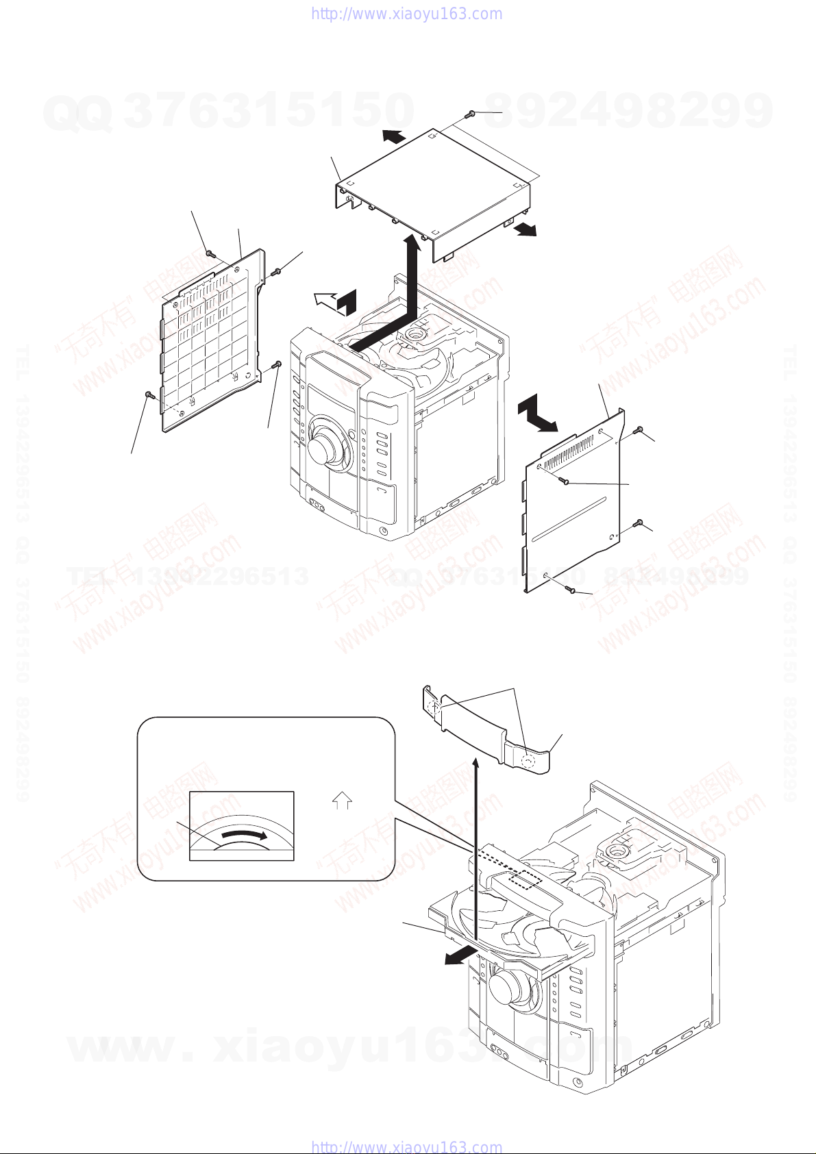
3-1. Cover (Top) ........................................................... 9
3-2. CD Door ................................................................ 9
3-3. Front Panel Section ............................................... 10
3-4. CD Mechanism Deck (CDM74-K6BD80)............ 10
3-5. Tape Mechanism Deck, GAME JACK Board ....... 11
3-6. PANEL Board........................................................ 11
3-7. Back Panel Section, SUB-TRANS Board............. 12
3-8. Power Transformer ................................................ 12
3-9. MAIN Board ......................................................... 13
3-10. AMP Board ........................................................... 13
3-11. BD80A Board........................................................ 14
3-12. CONNECT Board ................................................. 14
3-13. DRIVER Board, SW Board .................................. 15
3-14. Optical PICK-UP (KSM-213DCP/Z-NP) ............. 15
3-15. SENSOR Board ..................................................... 16
3-16. MOTOR (TB) Board ............................................. 16
3-17. MOTOR (LD) Board ............................................. 17
4. TEST MODE ............................................................... 18
5. DIAGRAMS
5-1. Block Diagram – PANEL Section – ...................... 22
5-2. Block Diagrams – MAIN Section – ...................... 23
5-3. Block Diagrams – BD/DRIVER Section – ........... 24
5-4. Printed Wiring Board – BD80A Section – ............ 25
5-5. Schematic Diagram – BD80A Section –............... 26
5-6. Printed Wiring Board
– CD MECHANISM Section – ............................. 27
5-7. Schematic Diagram
– CD MECHANISM Section – ............................. 28
5-8. Printed Wiring Board – MAIN Section –.............. 29
5-9. Schematic Diagram – MAIN Section (1/2) – ........ 30
5-10. Schematic Diagram – MAIN Section (2/2) – ........ 31
5-11. Printed Wiring Board
– PANEL COMB Section –................................... 32
5-12. Schematic Diagram
– PANEL COMB Section –................................... 33
5-13. Printed Wiring Board – PANEL Section – ............ 34
5-14. Schematic – PANEL Section (1/2) – ..................... 35
5-15. Schematic – PANEL Section (2/2) – ..................... 36
5-16. Printed Wiring Board – TRANS Section – ........... 37
5-17. Printed Wiring Board – AMP Section – ................ 38
5-18. Schematic Diagram – AMP POWER Section – .... 39
5-19. IC Pin Function Description.................................. 42
6. EXPLODED VIEWS
6-1. MAIN Section ....................................................... 48
6-2. Front Panel Section ............................................... 49
6-3. MAIN Board Section ............................................ 50
6-4. CD Mechanism Deck Section-1
(CDM74-K6BD80) ............................................... 51
6-5. CD Mechanism Deck Section-2
(CDM74-K6BD80) ............................................... 52
7. ELECTRICAL PARTS LIST .................................. 53
Unleaded solder
Boards requiring use of unleaded solder are printed with the lead-
free mark (LF) indicating the solder contains no lead.
(Caution: Some printed circuit boards may not come printed with
the lead free mark due to their particular size.)
: LEAD FREE MARK
Unleaded solder has the following characteristics.
•Unleaded solder melts at a temperature about 40°C higher than
ordinary solder.
Ordinary soldering irons can be used but the iron tip has to be
applied to the solder joint for a slightly longer time.
Soldering irons using a temperature regulator should be set to
about 350°C.
Caution: The printed pattern (copper foil) may peel away if the
heated tip is applied for too long, so be careful!
•Strong viscosity
Unleaded solder is more viscous (sticky, less prone to flow) than
ordinary solder so use caution not to let solder bridges occur
such as on IC pins, etc.
•Usable with ordinary solder
It is best to use only unleaded solder but unleaded solder may
also be added to ordinary solder.
w
w
w
.
x
i
a
o
y
u
1
6
3
.
c
o
m
Q
Q
3
7
6
3
1
5
1
5
0
9
9
2
8
9
4
2
9
8
T
E
L
1
3
9
4
2
2
9
6
5
1
3
9
9
2
8
9
4
2
9
8
0
5
1
5
1
3
6
7
3
Q
Q
TEL 13942296513 QQ 376315150 892498299
http://www.xiaoyu163.com

4
HCD-RG121
SECTION 1
SERVICE POSITION
•SERVICE POSITION-1 (AMP BOARD)
To inspect the AMP board, turn both of the front panel and the
CD mechanism deck so that the left side of the product faces
down.
front panel
CD mechanism deck
AMP boar
d
w
w
w
.
x
i
a
o
y
u
1
6
3
.
c
o
m
Q
Q
3
7
6
3
1
5
1
5
0
9
9
2
8
9
4
2
9
8
T
E
L
1
3
9
4
2
2
9
6
5
1
3
9
9
2
8
9
4
2
9
8
0
5
1
5
1
3
6
7
3
Q
Q
TEL 13942296513 QQ 376315150 892498299
http://www.xiaoyu163.com

5
HCD-RG121
•SERVICE POSITION-2 (BD80A BOARD)
Remove the CD mechanism deck and place it on top of the
pedestal as shown.
Inspect the BD80A bard in this set up.
BD80A board
CD mechanism dec
k
w
w
w
.
x
i
a
o
y
u
1
6
3
.
c
o
m
Q
Q
3
7
6
3
1
5
1
5
0
9
9
2
8
9
4
2
9
8
T
E
L
1
3
9
4
2
2
9
6
5
1
3
9
9
2
8
9
4
2
9
8
0
5
1
5
1
3
6
7
3
Q
Q
TEL 13942296513 QQ 376315150 892498299
http://www.xiaoyu163.com

6
HCD-RG121
SECTION 2
GENERAL
This section is extracted
from instruction manual.
Main unit
A
LBUM +1) qh (12, 14, 19)
A
LBUM –1) wg (12, 14, 19)
C
D eg (9, 11, 14, 19, 20)
C
D SYNC wj (19)
D
eck A wk (18)
D
eck B qj (18, 19, 20, 24)
D
ISC 1 – 3 q; (12, 14, 35)
D
ISC SKIP/EX-CHANGE qs
(11, 12, 14, 19)
D
isc tray 9(11)
D
ISPLAY 2(17, 27, 28)
D
isplay window 5
E
FFECT ON/OFF 8(22)
E
NTER qa (14, 15, 22)
E
Q BAND 7(22)
G
AME es (20, 23, 30)
G
AME INPUT AUDIO L/R jacks
wd (20, 29)
G
AME INPUT VIDEO jack wf
(29)
G
AME MIXING wh (23)
G
ROOVE 8(21)
I
LLUMINATION2) 3(28)
M
IC jack3) ws (24)
M
IC LEVEL3) wa (24)
O
peration Dial
(– EQ +/l L) 6(12,
14, 19, 22)
P FILE qd (22)
PHONES jack ql
PLAY MODE wl (12, 14, 18, 19,
20, 35)
Power illuminator2) qk (28)
PRESET EQ qd (22)
REC PAUSE/START wj (19, 20,
23, 24)
Remote sensor 4
SURROUND 8(23)
TAPE A/B ed (18, 19, 20, 24)
TUNER/BAND ef (15, 16, 20)
TUNING MODE wl (15, 16, 35)
TUNING + qh (15, 16)
TUNING – wg (15, 16)
VIDEO/MD3) ea (20, 30)
VOLUME control w; (21)
WIRELESS4) ea (32)
?/1 (power)1(8,16,27, 30, 33,
35)
X(pause) wg (12, 19)
Z(eject) qf (11)
PUSH Z(deck B) (eject) qg (18)
x(stop) wg (12, 19, 24, 35)
M(fast forward) qh (12, 19)
Hor hH3) (play) qh (12, 18,
19)
m(rewind) wg (12, 19)
ZPUSH (deck A) (eject) e; (18)
1) MHC-GX750/GX450/RG555/
RG551S/RG444S/RG441/
RG333/RG222/RG221/RX550
only
2) MHC-GX750/GX450/RG555/
RG551S/RG444S/RG441/
RG333/RX550 only
3) MHC-RG555 only
4) MHC-GX750 only
List of button locations and reference pages
How to use this page
Use this page to find the location of buttons and other
parts of the system that are mentioned in the text.
Ill
us
t
ra
ti
on num
b
er
r
TAPE A/B ed (18, 19, 20, 24)
RR
Name of button/part Reference page
ALPHABETICAL ORDER
A – O P – Z
BUTTON DESCRIPTIONS
ALBUM
ALBUM
TUNING TUNING
J
H
h
S
j
s
wd
12345 6 78 9
q;
qf
qa
qs
qd
w;
ql
waws
qg
qh
qk
wfwg
wh
wk
wj
wl
es
ea
ef
ed
eg
e;
qj
w
w
w
.
x
i
a
o
y
u
1
6
3
.
c
o
m
Q
Q
3
7
6
3
1
5
1
5
0
9
9
2
8
9
4
2
9
8
T
E
L
1
3
9
4
2
2
9
6
5
1
3
9
9
2
8
9
4
2
9
8
0
5
1
5
1
3
6
7
3
Q
Q
TEL 13942296513 QQ 376315150 892498299
http://www.xiaoyu163.com

7
HCD-RG121
Remote control
A
LBUM –* qd (12, 14)
A
LBUM +* qa (12, 14)
C
D qk (11, 14)
C
LEAR qg (14)
C
LOCK/TIMER SELECT 2
(26, 27)
C
LOCK/TIMER SET 3(10, 25,
26)
D
ISC SKIP q; (12, 14)
D
ISPLAY wa (17, 27, 28)
E
NTER 9(10, 14, 15, 25, 26)
E
Q qf (22)
FM MODE 4(17)
FUNCTION 6(11, 14, 15, 16)
PLAY MODE w; (12, 14, 18)
REPEAT 4(13)
SLEEP ws (25)
TAPE qj
TUNER BAND 5(15, 16)
TUNER MEMORY ql (15)
TUNING MODE w; (15, 16)
VOLUME +/– qs (21, 25)
?/1 (power) 1(8, 26)
m/M (rewind/fast forward)
7(12, 19)
–/+ (tuning) qh (15)
./> (go back/go forward
)
qh (10, 12, 19)
N(play) 8(12, 18)
X(pause) 8(12, 19)
x(stop) 8(12, 19)
*MHC-GX750/GX450/RG555
/
RG551S/RG444S/RG441/
RG333/RG222/RG221/RX55
0
only
ALPHABETICAL ORDER
A – E F – Z
BUTTON DESCRIPTIONS
4
5
6
7
8
9
q;
ws 1
qd
qg
qf
wa
w;
ql
qk
qj
qh
qa
qs
3
2
U
se buttons on the remote for the operation.
1
Press ?/1 to turn on the system.
2
Press CLOCK/TIMER SET.
3
Press .or >repeatedly to set the
hour.
4
Press ENTER.
5
Press .or >repeatedly to set the
minute.
6
Press ENTER.
The clock starts working.
To adjust the clock
1
Press CLOCK/TIMER SET.
2
Press .or >repeatedly to select
“CLOCK SET”, then press ENTER.
3
Do the same procedures as step 3 to 6
above.
Notes
The clock settings are canceled when you disconnec
t
the power cord or if a power failure occurs.
Setting the clock
w
w
w
.
x
i
a
o
y
u
1
6
3
.
c
o
m
Q
Q
3
7
6
3
1
5
1
5
0
9
9
2
8
9
4
2
9
8
T
E
L
1
3
9
4
2
2
9
6
5
1
3
9
9
2
8
9
4
2
9
8
0
5
1
5
1
3
6
7
3
Q
Q
TEL 13942296513 QQ 376315150 892498299
http://www.xiaoyu163.com

8
HCD-RG121
SECTION 3
DISASSEMBLY
3-1.COVER (TOP)
(Page 9)
3-2.CD DOOR
(Page 9)
3-3.FRONT PANEL SECTION
(Page 10)
3-8.POWER TRANSFORMER
(Page 12)
3-7.BACK PANEL SECTION,
SUB-TRANS BOARD
(Page 12)
3-4.CD MECHANISM DECK
(CDM74-K6BD80)
(Page 10)
3-14.OPTICAL PICK-UP
(KSM-213DCP/Z-NP)
(Page 15)
3-5.TAPE MECHANISM DECK,
GAME JACK BOARD
(Page 11)
3-13.DRIVER BOARD,
SW BOARD
(Page 15)
3-16.MOTOR (TB) BOARD
(Page 16)
3-17.MOTOR (LD) BOARD
(Page 17)
3-15.SENSOR BOARD
(Page 16)
3-11.BD80A BOARD
(Page 14)
3-6.PANEL BOARD
(Page 11)
3-9.MAIN BOARD
(Page 13)
3-10.AMP BOARD
(Page 13)
3-12.CONNECT BOARD
(Page 14)
SET
Note: Disassemble the unit in the order as shown below.
w
w
w
.
x
i
a
o
y
u
1
6
3
.
c
o
m
Q
Q
3
7
6
3
1
5
1
5
0
9
9
2
8
9
4
2
9
8
T
E
L
1
3
9
4
2
2
9
6
5
1
3
9
9
2
8
9
4
2
9
8
0
5
1
5
1
3
6
7
3
Q
Q
TEL 13942296513 QQ 376315150 892498299
http://www.xiaoyu163.com

9
HCD-RG121
3-1. COVER (TOP)
cover
(Side-R)
cover
(Side-L)
5
qd
qs
qs
q;
qf
cover
(top)
6
two screws (Case 3 TP2)
8
screw
(+BVTP 3
×
10
)
3
screw
(+BVTP 3
×
10
)
9
screw
(+BVTP 3
×
10
)
4
screw
(+BVTP 3
×
10
)
1
two screws
(case 3 TP2)
qa
two
screws (+BVTP 3
×
10)
7
screw (case 3 TP2)
2
screw (Case 3 TP2)
3-2. CD DOOR
2
Pull-out the disc tray.
1
Turn the pulley to the direction of arrow.
3
two claws
4
CD door
pulley
Front panel side
CD mechanism deck (CDM74B)
w
w
w
.
x
i
a
o
y
u
1
6
3
.
c
o
m
Q
Q
3
7
6
3
1
5
1
5
0
9
9
2
8
9
4
2
9
8
T
E
L
1
3
9
4
2
2
9
6
5
1
3
9
9
2
8
9
4
2
9
8
0
5
1
5
1
3
6
7
3
Q
Q
TEL 13942296513 QQ 376315150 892498299
http://www.xiaoyu163.com

10
HCD-RG121
3-3. FRONT PANEL SECTION
1
three screws (+BVTP 3
×
8
)
qd
front panel section
7
wire (flat type) 31 core (CN302)
8
wire (flat type) 7 core (CN253)
9
connector 5p (CN309)
qs
connector 8p (CN103)
3
screw (+BVTP 3
×
10)
2
screw (+BVTP 3
×
10)
4
screw (+BVTP 3
×
8
)
5
screw (+BVTP 3
×
8
)
0
connector 3p (CN314C)
qa
connector 3p (CN112)
6
connector 2p (CN805)
3-4. CD MECHANISM DECK (CDM74-K6BD80)
2
connector 12p (CN701)
3
connector 9p (CN254)
4
CD mechanism deck (CDM74-K6BD80)
1
three
screws (+BVTP 3
×
10
)
w
w
w
.
x
i
a
o
y
u
1
6
3
.
c
o
m
Q
Q
3
7
6
3
1
5
1
5
0
9
9
2
8
9
4
2
9
8
T
E
L
1
3
9
4
2
2
9
6
5
1
3
9
9
2
8
9
4
2
9
8
0
5
1
5
1
3
6
7
3
Q
Q
TEL 13942296513 QQ 376315150 892498299
http://www.xiaoyu163.com

11
HCD-RG121
3-5. TAPE MECHANISM DECK, GAME JACK BOARD
2
six
screws
(+BVTP 2.6
×
8)
6
GAME JACK board
3
TRANSRATION board
5
two
screws
(+BVTP 2.6
×
8)
4
tape mechanism deck
1
wire (flat type) 13 core (CN602)
3-6. PANEL BOARD
1
ten
screws
(+BVTP 2.6
×
8
)
5
PANEL board
4
connector 6p (CN604)
2
seven
claws
3
wire (flat type) 13 core (CN602)
w
w
w
.
x
i
a
o
y
u
1
6
3
.
c
o
m
Q
Q
3
7
6
3
1
5
1
5
0
9
9
2
8
9
4
2
9
8
T
E
L
1
3
9
4
2
2
9
6
5
1
3
9
9
2
8
9
4
2
9
8
0
5
1
5
1
3
6
7
3
Q
Q
TEL 13942296513 QQ 376315150 892498299
http://www.xiaoyu163.com

12
HCD-RG121
3-7. BACK PANEL SECTION, SUB-TRANS BOARD
1
connector
2p (CN904)
2
connector
2p (CN906)
7
connector
2p (CN901)
8
SUB-TRANS board
4
two
screws
(+BVTP 3
×
10
)
5
two
screws
(+BVTT 3
×
10)
6
two
screws
(+BVTT 3
×
10
)
9
back panel section
3
wire (flat type)
15 core (CN101)
3-8. POWER TRANSFORMER
1
connector
3p (CN905)
2
connector
10p (CN907)
4
earth wire
5
four
screws
(+ITC 4
×
8
)
3
screw
(+BVIT 3
×
8R)
6
power transforme
r
w
w
w
.
x
i
a
o
y
u
1
6
3
.
c
o
m
Q
Q
3
7
6
3
1
5
1
5
0
9
9
2
8
9
4
2
9
8
T
E
L
1
3
9
4
2
2
9
6
5
1
3
9
9
2
8
9
4
2
9
8
0
5
1
5
1
3
6
7
3
Q
Q
TEL 13942296513 QQ 376315150 892498299
http://www.xiaoyu163.com

13
HCD-RG121
3-9. MAIN BOARD
4
MAIN
boar
d
2
two
screws
(+BVTP 3
×
8
)
1
connector
10p (CN907)
3
connector
13p (CN441)
Main board
3-10. AMP BOARD
6
AMP
board
2
screw
(+BVTP 3
×
14)
4
two
screws
(transistor)
3
two
screws
(+BVIT 3
×
8R
)
1
two
screws
(+BVTT 3
×
8
)
5
heat sink
w
w
w
.
x
i
a
o
y
u
1
6
3
.
c
o
m
Q
Q
3
7
6
3
1
5
1
5
0
9
9
2
8
9
4
2
9
8
T
E
L
1
3
9
4
2
2
9
6
5
1
3
9
9
2
8
9
4
2
9
8
0
5
1
5
1
3
6
7
3
Q
Q
TEL 13942296513 QQ 376315150 892498299
http://www.xiaoyu163.com

14
HCD-RG121
3-11. BD80A BOARD
5
BD80A
board
3
screw
(+BVTP 2.6
×
8
)
1
wire (flat type) 17 core (CN201)
4
Remove soldering from the four points.
2
wire (flat type) 16 core (CN101
)
speacer
3-12. CONNECT BOARD
3
CONNECT
board
2
two
screws
(+BVTP 2.6
×
8
)
1
wire (flat type) 17 core (CN201)
w
w
w
.
x
i
a
o
y
u
1
6
3
.
c
o
m
Q
Q
3
7
6
3
1
5
1
5
0
9
9
2
8
9
4
2
9
8
T
E
L
1
3
9
4
2
2
9
6
5
1
3
9
9
2
8
9
4
2
9
8
0
5
1
5
1
3
6
7
3
Q
Q
TEL 13942296513 QQ 376315150 892498299
http://www.xiaoyu163.com

15
HCD-RG121
3-13. DRIVER BOARD, SW BOARD
3
connector
4p (CN703)
4
DRIVER
board
6
SW board
2
wire (flat type) 5p (CN702)
1
two
screws
(+BTTP (M2.6))
5
screw
(+BTTP (M2.6))
3-14. OPTICAL PICK-UP (KSM-213DCP/Z-NP)
5
two
coil springs
(insulator)
9
two
coil springs
(insulator)
6
two
insulators
0
two
insulators
qs
s
crew (+BVTP 2.6x 8)
7
t
wo screws
(BVTT M2.6)
3
screw
(BVTT M2.6)
2
h
older (213) ASSY
8
t
wo stoppers (BU)
qd
Remove the four solderings of motor.
qf
CN101 (flat type)
qg
B
D80A board
qh
optical pick-up
(KSM-213DCP/Z-NP)
1
floating
screw
(+PTPWH M2.6)
4
floating
screw
(+PTPWH M2.6)
qa
w
w
w
.
x
i
a
o
y
u
1
6
3
.
c
o
m
Q
Q
3
7
6
3
1
5
1
5
0
9
9
2
8
9
4
2
9
8
T
E
L
1
3
9
4
2
2
9
6
5
1
3
9
9
2
8
9
4
2
9
8
0
5
1
5
1
3
6
7
3
Q
Q
TEL 13942296513 QQ 376315150 892498299
http://www.xiaoyu163.com

16
HCD-RG121
3-15. SENSOR BOARD
2
t
ray
3
b
elt (table)
5
p
ulley (table)
8
s
crew
(+BTTP (M2.6))
0
SENSOR board
7
g
ear (geneva)
9
connector
(
CN731)
1
floating
screw
(+PTPWH M2.6)
6
floating
screw
(+PTPWH M2.6)
4
foating
screw
(+PTPWH M2.6)
3-16. MOTOR (TB) BOARD
6
Remove the two solderings of motor.
7
MOTOR (TB) board
5
t
able motor assy (M741)
5
two
screws
(+BTTP (M2.6))
4
3
wire (flat type) 5 core (CN742)
1
stopper
2
stopper
w
w
w
.
x
i
a
o
y
u
1
6
3
.
c
o
m
Q
Q
3
7
6
3
1
5
1
5
0
9
9
2
8
9
4
2
9
8
T
E
L
1
3
9
4
2
2
9
6
5
1
3
9
9
2
8
9
4
2
9
8
0
5
1
5
1
3
6
7
3
Q
Q
TEL 13942296513 QQ 376315150 892498299
http://www.xiaoyu163.com

17
HCD-RG121
3-17. MOTOR (LD) BOARD
4
Remove the two solderings of motor.
3
MOTOR (LD) board
1
b
elt (loading)
5
l
oading motor assy (M751)
2
two
screws
(+BTTP (M2.6))
w
w
w
.
x
i
a
o
y
u
1
6
3
.
c
o
m
Q
Q
3
7
6
3
1
5
1
5
0
9
9
2
8
9
4
2
9
8
T
E
L
1
3
9
4
2
2
9
6
5
1
3
9
9
2
8
9
4
2
9
8
0
5
1
5
1
3
6
7
3
Q
Q
TEL 13942296513 QQ 376315150 892498299
http://www.xiaoyu163.com

18
HCD-RG121
SECTION 4
TEST MODE
Step
1
2
3
4
5
6
7
8
9
10
11
12
Operation
Rewind the TAPE A
Rewind the TAPE B
Play the TAPE A (1 minute)
Stop the TAPE A (1 second)
Play the TAPE A (3 minutes)
Rewind(AMS) the TAPE A
F.F.(AMS) the TAPE A
Play the TAPE B (1 minute)
Stop the TAPE B (1 second)
Record the TAPE B (3 minutes)
Rewind(AMS) the TAPE B
F.F.(AMS) the TAPE B
Display
TAPE AAG-1
TAPE BAG-2
TAPE AAG-2
TAPE AAG-3
TAPE AAG-4
TAPE AAG-5
TAPE AAG-6
TAPE BAG-2
TAPE BAG-3
TAPE BAG-4
TAPE BAG-5
TAPE BAG-6
Disc error
Display Error
E00D01022 Focus error (No disc)
E00D02022 Sub Q error (Focus is good)
E00D02023 TOC reading error
E00D02014 Access error (Unable within regular time)
Mechanism error
Display Error
E00M__E_0 Error during opening tray
E00M__C_2 EX-CHANGE disc error
E00M__D_0 Error during closing tray
E00M__F_3 EX-OPEN error
E00M__D_5 EX-CLOSE error
E00M__C_2 Chuck-up error
E00M__C_3 Unchucking error
2) Error display
•If error occurred, the display remains like “TAPE BAG-2”.
4. Exiting from the aging mode
•Be sure to perform Cold Reset to exit from the aging mode.
[Change-over of AM Tuner Step between 9 kHz and
10 kHz]
•Astep ofAM channels can be changed over between 9 kHz and
10 kHz.
Procedure:
1. Press ?/1button to turn the set ON.
2. Select the function “TUNER”, and press TUNER/BAND
button to select the BAND “AM”.
3. Press ?/1button to turn the set OFF.
4. Press TUNER/BAND and ?/1buttons simultaneously, and
the display of fluorescent indicator tube changes to “AM 9 k
STEP”or “AM 10 kSTEP”, and thus thechannel step ischanged
over.
[Cold Reset]
•The cold reset clears all data including preset data stored in the
RAM to initial conditions. Execute this mode when returning
the set to the customer.
Procedure:
1. Press three buttons x, PLAY MODE/TUNING MODE ,
and DISC1 simultaneously.
2. The fluorescent indicator tube displays “COLD RESET” and
the set is reset.
[Aging Mode]
This mode can be used for operation check of CD section and tape
deck section.
•If an error occurred:
The aging operation stops and is displayed status.
•If no error occurs:
The aging operation continues repeatedly.
1. Operating method of Aging Mode
Turn on the main power and select “CD” of the function.
1) Set three discs in tray. SelectALL DISCS, and REPEAT OFF.
2) Load the tapes recording use into both decks.
3) Press three buttons x, PLAY MODE/TUNING MODE ,
and EX-CHANGE simultaneously.
4) Aging operations of CD and tape are started at the same time.
5) To exit the aging mode, perform [Cold Reset].
2. Aging mode in CD section
1) Operation during aging mode
•In the agining mode ,the program is excuted in the following
sequence.
(1) The disc tray opens and closes.
(2) The disc tray turns to select a disc 3.
(3) The pick-up accesses to the first track, and plays 3 seconds.
(4) The pick-up accesses to the last track, and plays 3 seconds.
(5) The disc tray opens and closes.
(6) The disc tray turns to select a disc 1.
(7) The same operation starts like step (3).
(8) After a disc 1 aging operation, a disc 2 is selected.
(9) When an aging operation of a disc 3 is completed, the display
“AGING ∗∗∗∗” value increases.
(10) If no error occurs, the aging operation continues repeatedly.
2) Error display
3. Aging mode in Tape Deck section
1) Operation during aging mode
•In the agining mode, the program is excuted in the following
sequence.
w
w
w
.
x
i
a
o
y
u
1
6
3
.
c
o
m
Q
Q
3
7
6
3
1
5
1
5
0
9
9
2
8
9
4
2
9
8
T
E
L
1
3
9
4
2
2
9
6
5
1
3
9
9
2
8
9
4
2
9
8
0
5
1
5
1
3
6
7
3
Q
Q
TEL 13942296513 QQ 376315150 892498299
http://www.xiaoyu163.com

19
HCD-RG121
[MC Test Mode]
•This mode is used to test the function of the equalizer.
Procedure:
1. Press ?/1button to turn the set ON.
2. To enter the test mode, press the three buttons x ,
PLAY MODE/TUNING MODE and DISC 3 simultaneously.
3. Press the EQ+ button.
The function of the equalizer is set to “MIN”.
4. Press the EQ– button.
The function of the equalizer is set to “MAX”.
5. Press the PRESET EQ button.
The function of the equalizer is set to “EQ FLAT”.
6. MASTER VOLUME up and down.
“VOLUME MIN”, “VOLUME 16”, “VOLUME MAX” is
displayed.
7. Press GROOVE button.
The message “VACS OFF” on “VACS ON” is dislayed.
8. To exit from this mode, press ?/1button to turn the set OFF.
[CD Ship Mode (LOCK) ]
•This mode moves the pick-up to the position durable to vibra-
tion. Use this mode when returning the set to the customer after
repair.
Procedure:
1. Press ?/1button to turn the set ON.
2. Select the function “CD”.
3. Press ?/1button to turn the set OFF.
4. Press CD button and ?/1button simultaneously.
5. The “STANDBY” display blinks instantaneously, and the CD
ship mode is set.
[CD Ship (LOCK) & COLD RESET MODE]
Procedure:
1. Press ?/1button to turn the set ON.
2. Select the function “CD”.
3. Press ?/1button to turn the set OFF.
4. Press three buttons x, CD and DISPLAY simultaneously.
5. The “STANDBY” display blinks instantaneously and CD ship
mode is set.
6. The fluorescent indicator tube displays “COLD RESET” and
the set is reset.
[Disc Tray Lock]
Procedure:
1. Press the ?/1 button to turn the set ON.
2. Presstwobuttonsof xand Zsimultaneouslyforfive seconds.
3. The message “LOCKED” is displayed and the tray is locked.
(Even if exiting from this mode, the tray is still locked.)
4. Presstwobuttonsof xand Zsimultaneouslyforfiveseconds
again.
5. The message “UNLOCKED” is displayed and the tray is
unlocked.
6. To exit from this mode, press the ?/1 button to turn the set
OFF.
[PANEL Test Mode]
•All fluorecent segments and LEDs are tested.
•Keyboard check.
Procedure:
1. Press ?/1button to turn the set ON.
2. To enter the test mode, press the three buttons x ,
PLAY MODE/TUNINGMODE and ENTER simultaneously.
3. All segments and LEDs (without STANDBY LED) are turned
on.
4. Press Xand ENTER buttons simultaneously, and the key
check mode is activated.
5. The message “KEY 0 0 0” is displayed.
Each time a button is pressed, the key code number is displayed.
6. Press Xand ENTER buttons simultaneously, and the key
count mode is activated.
7. The message “KEYCNT 0” is displayed.
Each time a button is pressed, “KEYCNT 0” value increased.
However, once a button is pressed, it is no longer taken into
account.
8. Press Xand ENTER buttons simultaneously, and the head
phone detect mode is activated.
9. The message “H_P OFF” is displayed when a headphone jack
is not inserted.
“H_P ON ” is displayed when a headphone jack is inserted.
10. Press Xand ENTER buttons simultaneously, and the volume
control detect mode is activated.
11. The message “VOLUME FLAT” is displayed.
“VOLUME UP” is displayed if rotating MASTER VOLUME
knob clockwise, or “VOLUME DOWN” is displayed if rotating
counterclockwise.
12. To exit from the GC test mode after the head phone detect mode,
press Xand ENTER buttons simultaneously.
[Version and Destination Display Mode]
•The version or destination is displayed.
Procedure:
1. Press ?/1button to turn the set ON.
2. To enter the test mode, press the three buttons x ,
PLAY MODE/TUNING MODE and DISC2 simultaneously.
3. The destination is displayed.
4. Press DISPLAY buttons simultaneously.
5. The version is displayed.
6. To exit from this mode, press ?/1button to turn the set OFF.
[CD Service Mode]
•This mode can run the CD sled motor freely. Use this mode, for
instance, when cleaning the pick-up.
Procedure:
1. Press ?/1button to turn the set ON.
2. Select the function “CD”.
3. To enter the test mode, press three buttons x,
PLAY MODE/TUNING MODE , and Zsimultaneously.
4. The CD service mode is selected.
5. With the CD in stop status, press M button to move the pick-
up to outside track, or press m button to inside track.
6. To exit from this mode, perform as follows:
1) Move the pick-up to the most inside track.
2) Press ?/1button to turn the set OFF.
Note: • Always move the pick-up to most inside track when exiting from
this mode. Otherwise, a disc will not be unloaded.
•Do not run the sled motor excessively, otherwise the gear can be
chipped.
w
w
w
.
x
i
a
o
y
u
1
6
3
.
c
o
m
Q
Q
3
7
6
3
1
5
1
5
0
9
9
2
8
9
4
2
9
8
T
E
L
1
3
9
4
2
2
9
6
5
1
3
9
9
2
8
9
4
2
9
8
0
5
1
5
1
3
6
7
3
Q
Q
TEL 13942296513 QQ 376315150 892498299
http://www.xiaoyu163.com

20
HCD-RG121
[CD Repeat 5 Times Limit Release Mode]
Procedure:
1. Press ?/1button to turn the set ON.
2. Select the function “CD”.
3. Press three buttons x, CD and ENTER simultaneously.
4. The message “LIMIT OFF” is displayed.
5. Press ?/1button the set OFF.
[AMP TEST MODE]
Procedure:
1. Press ?/1button to turn the set ON.
2. To enter the test mode, press the three buttons x,
PLAY MODE/TUNING MODE and ENTER simultaneously.
3. Press the DISPLAY button.
The message “V0 0 0” “ 000” is displayed.
4. Press the GROOVE button.
The message “DBFB ON” “DBFB OFF” is displayed.
5. Press the SURROUND button.
The message “SURROUND ON” “SURROUND OFF” is
displayed.
6. Press the EQ BAND button.
The message “LOW” “MID” “HIGH” is displayed.
7. Press ?/1button to turn the set OFF.
w
w
w
.
x
i
a
o
y
u
1
6
3
.
c
o
m
Q
Q
3
7
6
3
1
5
1
5
0
9
9
2
8
9
4
2
9
8
T
E
L
1
3
9
4
2
2
9
6
5
1
3
9
9
2
8
9
4
2
9
8
0
5
1
5
1
3
6
7
3
Q
Q
TEL 13942296513 QQ 376315150 892498299
http://www.xiaoyu163.com
Other manuals for HCD-RG121
1
Table of contents
Other Sony Stereo System manuals

Sony
Sony HCD-GT22 Quick start guide

Sony
Sony LBT-V3500 User manual

Sony
Sony XDR-DS16iPN User manual

Sony
Sony PMC-D407L User manual

Sony
Sony CMT-GS10 User manual

Sony
Sony H.ear go SRS-HG1 User manual

Sony
Sony HCD-VX3A User manual

Sony
Sony HCD-EC55 - Receiver System User manual

Sony
Sony LBT-XGR88 User manual

Sony
Sony FST-ZX6 User manual