7
Basic Setups
When the monitor is connected via the DVI-I OUT connector
1
Perform steps 1to 4of “When the monitor is connected via the AUX1
connector.”
2
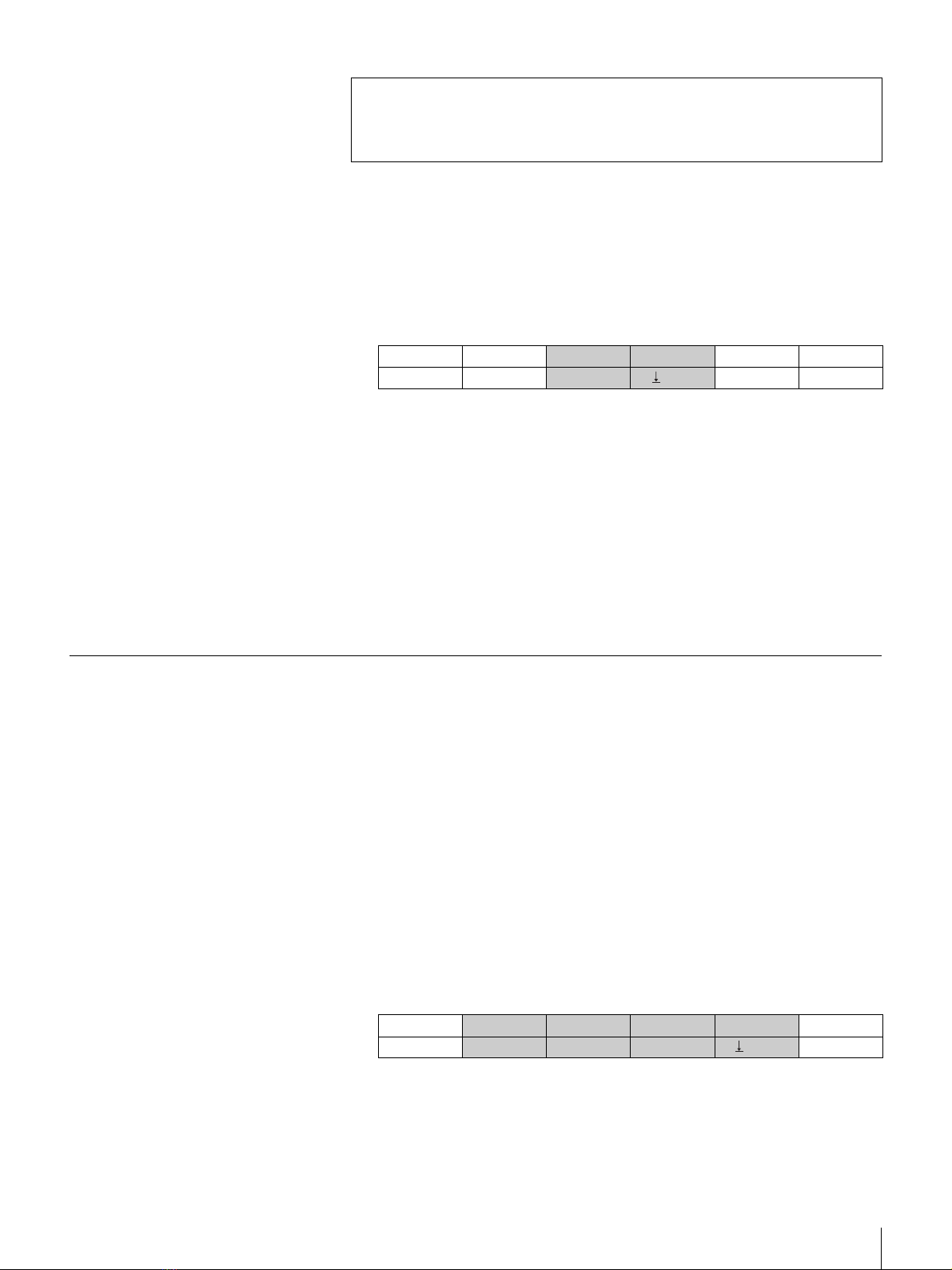
Display menu page 932 by pressing buttons MENU t9 t. (dot) t
3 t2 in order.
3
Turn the F2 control to select “AUX1” under “BUSSEL.”
In AUX1 position, the video signal output from the DVI-I OUT connector
becomes the same as that from the AUX1 connector.
4
Turn the F3 control to select the resolution of the output signal under
“RESO” then press the F3 control.
You can select the resolution from among “XGA,” “WXGA,” and
“SXGA.”
When “FORMAT” is “HD,” “HD 59.94” (or “HD 50”) and “WUXGA” are
also available.
Setting Up the VISCA Camera
Set the VISCA communication mode to control the camera with the switcher.
This section explains how to set it to RS-232C according to the premised system
configuration.
To confirm the settings on the camera
Check that the following settings have been made on the camera.
– VISCA communication mode: RS-232C
– Communication baud rate: 9600 bps or 38400 bps
– Camera address selector: position 0 (automatic assignment)
To set the VISCA communication mode
1
Display menu page 911 by pressing buttons MENU t9 t. (dot) t
1 t1 in order.
2
Set the VISCA communication mode and the baud rate to the same
settings as those on the camera, by turning the F1 and F2 controls.
CONTROL: RS-232C
BAUD: 9600 or 38400
When you press the SW mode button, the message “Save setup data? [PAGE]
(yes) or [EXIT] (no)” may appear on the display panel. Press the PAGE button.
The changed setting will be saved, and the switcher will enter the SW
(switcher) mode.
OUTPUT BOARD BUSSEL RESO 2/6
DVI STD PGM XGA 932
CAMERA CONTROL BAUD MODEL APPLY 1/8
VISCA RS-232C 9600 Auto Exec 911