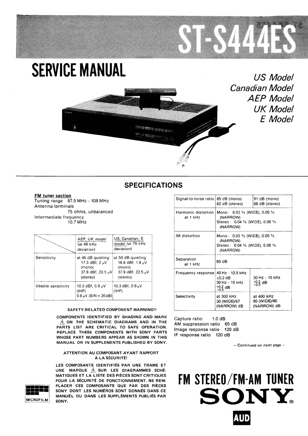
Sony ST-S444ES User manual

>
FM
tuner
section
: : :
—s]
Tuning
range
87.5
MHz
-
108
MHz
Signal-to-noise
ratio
5
is
el
ns
Gene
Antenna
terminals
Pe
75
ohms,
unbalanced
Harmonic
distortion
|Mono:
0.03
%
(WIDE),
0.05
%
Intermediate
frequency
at
1
kHz
(NARROW)
10.7
MHz
Stereo:
0.04
%
(WIDE),
0.06
%
(NARROW)
;
IM
distortion
Mono:
0.03
%
(WIDE),
0.05
%
AEP,
UK
model
|
US,
Canadian,
€
Nesdon
Re
(at
40
kHz
model
(at
75
kHz
|
Stereo:
0.04
%
(WIDE),
0.06
%
deviation)
deviation)
|
(NARROW)
|
é
Sensitivity
at
46
dB
quieting
|at50
dB
quieting
|
Separation
17.3
dBf,
2
uV
16.8
dBf,
1.8
pV
at
1
kHz
60
dB
(mono)
(mono)
37.9
dBf,
22.5
yV|
37.9
dB,
22.5
pV
Frequency
response
|
40
Hz
-
12.5
kHz
(stereo)
(stereo)
+0.2
dB
30
Hz
-
15
KHz
r
30
Hz
-
15
kHz
+0.2
dB
Usable
sensitivity
|10.3
dBf,0.9yV
|
10.3
dBf,
0.94V
+0.2
dB
ve
(IHF)
(IHF)
~0.5
0.8
pV
(S/N
=
26
dB)
Selectivity
at
300
kHz
at
400
kHz
30
(WIDE)/57
60
(WIDEV90
_
(NARROW)
dB
(NARROW)
dB
MICROFILM
}
SAFETY-RELATED
COMPONENT
WARNING!!
COMPONENTS
IDENTIFIED
BY
SHADING
AND
MARK
A
ON
THE
SCHEMATIC
DIAGRAMS
AND
IN
THE
PARTS
LIST
ARE
CRITICAL
TO
SAFE
OPERATION.
REPLACE
THESE
COMPONENTS
WITH
SONY
PARTS
WHOSE
PART
NUMBERS
APPEAR
AS
SHOWN
IN
THIS
MANUAL
OR
IN
SUPPLEMENTS
PUBLISHED
BY
SONY.
ATTENTION
AU
COMPOSANT
AYANT
RAPPORT
A
LA
SECURITE!
LES
COMPOSANTS
IDENTIFIES
PAR
UNE
TRAME
ET
UNE
MARQUE
A
SUR
LES
DIAGRAMMES
SCHE-
MATIQUES
ET
LA
LISTE
DES
PIECES
SONT
CRITIQUES
POUR
LA
SECURITE
DE
FONCTIONNEMENT.
NE
REM-
PLACER
CES
COMPOSANTS
QUE
PAR
DES
PIECES
SONY
DONT
LES
NUMEROS
SONT
DONNES
DANS
CE
MANUEL
OU
DANS
LES
SUPPLEMENTS
PUBLIES
PAR
SONY.
US
Model
Canadian
Model
AEP
Model
UK
Model
E
Model
Capture
ratio
1.0
dB
AM
suppression
ratio
65
dB
Image
response
ratio
120
dB
IF
response
ratio
120
dB
—
Continued
on
next
page
—
FM
STEREO
/FM-AM
TUNER
ON
Y.

ST-S444ES
Spurious
response
ratio
120
dB
RF
intermodulation
88
dB
(IHF)
Muting
threshold
Approx.
29
dBf,
8uV
Auto
tuning
threshold
Approx.
29
dBf,
8uV
Output
level/impedance
at
75
kHz
deviation
750
mV,
620
ohms
Cal
tone
400
Hz,
50
%
mod
AM
tuner
section
Tuning
range
AEP,
UK,
E
model:
531
-
1,602
kHz
US,
Canadian,
E
model:
531
-
1,602
kHz
(with
the
AM
channel
plan
selector
set
at
9
kHz)
530
-
1,610
kHz(with
the
AM
channel
plan
selector
set
at
10
kHz)
LAYOUT-FREE
AM
antenna
External
antenna
terminal
Intermediate
frequency
450
kHz
Usable
sensitivity
LAYOUT-FREE
AM
antenna
300
pV/m
(at
999
or
1,000
kHz)
External
antenna
30
uV
(at
999
or
1,000
kHz)
Signal-to-noise-ratio
Antenna
54dB
Harmonic
distortion
0.3
%
Selectivity
AEP,
UK
model:
35
dB
US,
Canadian,
E
model:
35
dB
(9
kHz),
38
dB
(10
kHz)
Image
response
ratio
42
dB
(at
999
or
1,000
kHz)
Auto-tuning
threshold
Approx.
1mV/m
General
System
PLL
quartz-locked
digital
synthesizer
system
FM
stereo,
FM/AM
super-heterodyne
tuner.
Power
requirements
AEP
model:
220
V
ac
(or
240
V
ac
adjustable
by
authorized
Sony
personnel),
50/60
Hz
UK
model:
240
V
ac
(or
220
V
ac
adjustable
by
authorized
Sony
personnel),
50
Hz
US,
Canadian
model:
120
V
ac,
60
Hz
E
model:
120,
220
or
240
V
ac
adjustable,
50/60
Hz
Power
consumption
18
watts
Dimensions
Approx.
430
x
80
x
340
mm
(w/h/d)
(17
x
34/4
x
134/2
inches)
including
projecting
parts
and
controls
Weight
Approx.
4.4
kg
(12
Ibs
21
02)
net
While
the
information
given
is
true
at
the
time
of
print-
ing,
small
production
changes
in
the
course
of
our
com-
pany’s
policy
of
improvement
through
research
and
design
might
not
necessarily
be
indicated
in
the
specifications.
We
would
ask
you
to
check
with
your
ap-
pointed
Sony
dealer
if
clarification
on
any
point
is
required.
PDP
PL
PL
LL
LLL
LL DL
LDL
DL
DL
DL
DOLL
DLL
LLL
LL
LDL
PDO
DOLL
DL
DL
LLLP
DL
LDS
LDL
DL
LL
POLL
DLL LOL
LLL ODL
OEP
DO
OE
OL
OE
OOD LOL
OCOCOOOR
OOD
~
MODEL
IDENTIFICATION
—
(Specification
Label)
SONY:
FM
STEREO/FM-AM
TUNER
MODEL
NO,
ST-S444ES
US
model:
AC120V
60Hz
18W
Canadian
model:
AC120V
60Hz
18W
AEP
model:
AC
220V~
50/60Hz
18W
UK
model:
AC
240V~
50/60Hz
18W
E
model:
AC
120/220/240V
~
50/60Hz
18W

SAFETY
CHECK-OUT
(US
Model)
After
correcting
the
original
service
problem,
perform
the
following
safety
check
before
releasing
the
set
to
the
customer:
Check
the
antenna
terminals,
metal
trim,
‘“‘metallized”
knobs,
screws,
and
all
other
exposed
metal
parts
for
AC
leakage.
Check
leakage
as
described
below.
LEAKAGE
TEST
The
AC
leakage
from
any
exposed
metal
part
to
earth
ground
and
from
all
exposed
metal
parts
to
any
exposed
metal
part
having
a
return
to
chassis,
must
not
exceed
0.5mA
(500
microamperes).
Leakage
current
can
be
measured
by
any
one
of
three
methods.
1.
N
Fig.
A.
Using
an
AC
voltmeter
to
check
AC
leakage.
A
commercial
leakage
tester,
such
as
the
Simpson
229
or
RCA
WT-540A.
Follow
the
manufacturers’
instructions
to
use
these
instru-
ments.
A
battery-operated
AC
milliammeter.
The
Data
Precision
245
digital
multimeter
is
suitable
for
this
job.
Measuring
the
voltage
drop
across
a
resistor
by
means
of
a
VOM
or
battery-operated
AC
volt-
meter.
The
“limit”
indication
is
0.75
V,
so
analog
meters
must
have
an
accurate
low-
voltage
scale.
The
Simpson
250
and
Sanwa
SH-63Trd
are
examples
of
a
passive
VOM
that
is
suitable.
Nearly
all
battery
operated
digital
multimeters
that
have
a
2V AC
range
are
(See
Fig.
A)
suitable.
To
Exposed
Metal
Parts
on
Set
AC
voltmeter
0.15
uF
°
(0.75
V)
ie
5kQ
ae
+
Earth
Ground
ST-S444ES
FEATURES
PLL-CIRCUIT
EMPLOYING
DIRECT
COMPARATOR
TECHNOLOGY
The
ST-S444ES
with
its
refined
Phase
Locked
Loop
(PLL)
circuit
can
tune
to
a
frequency
with
extraordinary
precision.
An
IC
developed
by
Sony
allows
the
comparison
fre-
quency
to
be
as
high
as
the
50
kHz
channel
spacing
fre-
quency,
thus
eliminating
the
tendency
of
a
low
com-
parison
frequency,
which
was
formerly
generally
em-
ployed,
to
slip
into
the
audio
range
and
degrade
the
signal-to-noise
ratio.
The
local
oscillator
output
can
therefore
be
directly
supplied
to
the
programmable
divider
section
without
an
additional
pre-scaler.
We
call
this
PLL-circuit
technology
the
Direct
Comparator
meth-
od.
The
result
is
almost
rippleless
local
oscillation,
greatly
reduced
spurious
radiation,
and
an
extremely
high
signal-to-noise
ratio.
STATE
OF
THE
ART
Every
element
of
the
ST-S444ES
is
chosen
with
an
eye
to
optimum
reception.
Dual-gate
MOS
FETs
in
the
RF
amplifier,
and
five
varactors
in
the
front-end
block
in-
sure
high
sensitivity
and
an
excellent
spurious
response
ratio.
Four
uni-phase
filters
in
the
IF
amplifier
provide
high
selectivity.
The
PLL
multiplex
decoder
with
a
pilot
canceler
insures
a
flat
frequency
response,
clear
sepa-
ration
and
very
low
distortion.
EFFORTLESS
TUNING
Tuning
is
easy
using
the
digital
frequency
readout
in
the
frequency
display
window.
Three
methods
of
tuning
are
available
:
Automatic
tuning,
in
which
the
entire
AM
or
FM
band
is
scanned
automatically
until
a
signal
is
received.
Manual
tuning,
in
which
the
AM
or
FM
band
can
be
scanned
either
rapidly
or
step-by-step.
Memory
preset
tuning,
in
which
the
frequencies
of
up
to
eight
stations
can
be
stored.
In
this
mode,
this
infor-
mation
will
be
retained
when
the
power
is
turned
off
so
that
you
can
tune
in
your
favorite
station
with
the
push
of
a
button.
Various
conditions
can
also
be
memorized
for
each
individual
station
to
permit
one-touch
reception.
All
the
memorized
settings
are
displayed
in
the
FL
display
window.
The
SCAN/READ
button
allows
you
to
scan
automa-
tically
the
preset
stations
only,
listening
to
each
one
for
a
few
seconds
to
check
if
there
is
anything
you
would
like
to
listen
to.

ST-S444ES
A.C.T.
(AUDIO
CURRENT
TRANSFER)
CIRCUIT
This
tuner
employs
the
A.C.T.
technique
developed
for
Sony
integrated
amplifiers.
The
A.C.T.
circuit
design
vir-
tually
eliminates
the
problems
which
the
conventional
voltage
transfer
design
had:
electrical
interference
be-
tween
the
left
and
right
channels,
decreased
sound
quality,
distortion,
noise,
etc.
caused
by
the
fact
that
both
the
signal
source
current
and
the
power
supply
cur-
rent
flow
through
the
same
ground.
This
technique
insures
the
tuner’s
high-quality
recep-
tion
performance.
PROGRAM
FUNCTION
Using
the
Program
Function,
you
can
automatically
tune
in
to
up
to
four
stations
which
have
been
memoriz-
ed
in
any
sequence
you
want.
Stations
will
be
received
one
by
one
as
the
power
is
turned
on
and
off
by
an
op-
tional
timer.
This
Program
Function
enables
timer-
activated
reception
or
recording
of
a
number
of
stations
as
compared
to
the
single
station
capability
of
conven-
tional
tuners.
OTHER
REFINEMENTS
The
HI-BLEND
switch
reduces
noise
in
FM
stereo
rece-
tion.
The
ten-step
SIGNAL
indicator
shows
the
strength
of
the
tuned
signal.
The
CAL
(CALibration)
TONE
button
produces
a
400
Hz,
50
%
mod.
signal
(equivalent
to
37.5
kHz
deviation),
which
is
useful
for
calibrating
the
recording
level
on
a
tape
deck.
The
two-pole
beat-cut
filter
is
positioned
before
the
multi-
plex
circuit
to
assure
better
FM
stereo
reception.
OPERATING
VOLTAGE
Before
connecting
the
unit
to
the
power
source,
check
that
the
operating
voltage
of
your
unit
is
the
same
as
the
local
power
line
voltage.
AEP
mode!
operates
on
220
V
ac
(or
240
V
ac
adjustable
by
authorized
Sony
personnel).
.
UK
model
operates
on
240
V
ac
(or
220
V
ac
adjustable
by
authorized
Sony
personnel).
The
USA
and
Canada
models
operate
only
on
120
V
ac.
The
E
model
operates
on
either
120,
220
or
240
V
ac.
The
voltage
selector
is
located
on
the
rear
panel.
If
the
selector
must
be
reset,
disconnect
the
ac
power
cord
and
turn
the
selector
with
a
coin
so
that
the
arrow
mark
of
the
selector
points
to
the
proper
voltage
figure.
PRECAUTIONS
On
safety
eBefore
operating
the
unit,
be
sure
that
the
operating
voltage
of
your
unit
is
identical
with
that
of
your
local
power
supply.
eShould
any
liquid
or
soild
object
fall
into
the
cabinet,
unplug
the
unit
and
have
it
checked
by
qualified
person-
nel
before
operating
it
any
further.
e
Unplug
the
unit
from
the
wall
outlet
if it
is
not
to
be
used
for
an
extended
period
of
time.
To
disconnect
the
cord,
pull
it
out
by
grasping
the
plug.
Never
pull
it
out
by
the
cord.
On
installation
eDo
not
install
the
unit
in
a
location
near
heat
sources
such
as
radiators
or
air
ducts,
or
in
a
place
subject
to
direct
sunlight,
excessive
dust,
mechanical
vibration
or
shock.
eGood
air
circulation
is
essential
to
prevent
internal
heat
build-up
in
the
unit.
Place
the
unit
in
a
location
with
adequate
air
circulation.
On
operation
eWhen
the
unit
is
not
in
use,
turn
the
power
off
to
con-
serve
energy
and
to
extend
the
useful
life
of
your
unit.
eSet
the
PROGRAM
switch
to
OFF
when
the
Program
Function
is
not
being
used.
If
this
is
not
done,
you
can-
not
tune
with
the
TUNING
or
station
preset
buttons.
On
cleaning
Clean
the
cabinet,
front
and
rear
panels
periodically
with
a
soft
dry
cloth.
If
the
stains
are
difficult
to
remove,
use
a
cloth
moistened
with
a
mild
detergent
solution.
Do
not
use
solvents
such
as
alcohol,
benzine
or
thinner,
since
they
will
damage
the
finish.
On
repacking
Do
not
throw
away
the
carton
and
the
packing
material.
It
makes
an
ideal
container
to
transport
the
unit
in.
When
shipping
the
unit
for
repair
work
or
to
another
location,
repack
it
as
illustrated
on
the
carton
box.
For
the
customers
in
the
USA
For
detailed
safety
precautions,
see
the
leaflet
“IMPOR-
TANT
SAFEGUARDS”.
Note
about
the
AM
channel!
plan
selector
This
tuner
has
a
two-position
AM
channel
plan
selector
underneath
the
right
front
corner.
To
tune
in
AM
sta-
tions
correctly,
the
selector
should
be
correctly
set
ac-
cording
to
the
AM
frequency
allocation
system
of
your
country.
9kHz:
for
countries
where
the
frequencies
are
allo-
cated
at
intervals
of
9
kHz.
10
kHz:
for
countries
where
the
frequencies
are
allo-
cated
at
intervals
of
10
kHz,
for
example,
the
USA
and
Canada.
This
selector
is
factory
preset.
If
the
AM
frequencies
are
not
allocated
at
intervals
in
your
country,
the
selector
setting
should
be
changed.
Be
sure
to
turn
off
the
power
before
changing
the
position
of
the
selector.

SECTION
1
ST-S444ES
OUTLINE
1-1.
FUNCTION
OF
CONTROLS
Each
number
in
the
text
is
keyed
to
that
of
the
photo
above.
@
POWER
switch
Depress
to
turn
on
the
power.
To
turn
the
power
off,
press
the
switch
again.
@
TUNE
MODE
button
To
tune
in
a
station
with
the
automatic
tuning
system,
press
this
button
so
that
the
TUNING
AUTO
indicator
lights
up.
When
you
want
to
tune
with
manual
tuning
system,
press
the
button
again
so
that
the
TUNING
MANUAL
in-
dicator
lights
up.
AM
(FY
EI
TT)
kHz
FM
Li
Li,
|
MHz
STEREO
12345678910
HI-BLENDe
ON
leds
MUTING
e
ON.
lelag
le]8]
3
e
STEREO
MONO
|
TUNING
«
AUTO
MANUAL
SIGNAL
PROGRAMM
1.20314)
iF
BAND
*
WIDE
NARROW
“wl
|
©
MUTING/MODE
button
This
button
serves
a
dual
purpose:
it
is
a
muting
switch
and
FM
mode
selector.
To
tune
in
a
strong
FM
station,
press
the
button
so
that
the
MUTING
ON
and
MODE
STEREO
indicators
light
up.
In
this
mode,
the
muting
circuit
will
pe
activated
to
eliminate
interstation
noise
while
tuning
and
the
FM
station
will
be
received
in
stereo
mode.
When
you
want
to
tune
in
a
very
weak
FM
staion,
press
the
button
again
so
that
the
MUTING
OFF
and
MODE
MONO
indicators
light
up.
The
muting
circuit
will
be
deactivated
and
the
FM
station
is
received
in
monaural
mode.
In
this
mode,
keep
the
amplifier
volume
down
to
avoid
speaker
damage
caused
by
interstation
noise
dur-
ing
tuning.
—5—
ST-S444ES
©
FM/AM
selector
button
Selects
the
desired
band:
FM
or
AM.
The
selected
band
wili
be
indicated
in
the
display
window.
©
!F
BAND
button
Normally
press
this
button
so
that
the
IF
BAND
WIDE
in-
dicator
lights
up.
Low-distortion,
hi-fi
FM
broadcasting
sound
can
be
obtained.
When
there
is
interference
by
adjacent
stations,
press
the
button
so
that
the
IF
BAND
NARROW
indicator
lights
up.
The
higher
selectivity
will
improve
the
reception.
@
HI-BLEND
button
When
FM
stereo
signals
are
weak
and
noisy,
press
this
button
so
that
the
HI-BLEND
ON
indicator
lights
up.
This
will
provide
better
reception,
although
the
stereo
effect
at
high
frequencies
is
slightly
reduced.
To
deactivate
the
high-biend
circuit,
press
the
button
again.
The
HI-BLEND
OFF
indicator
will
light
up.
@
CAL
TONE
button
Normally
press
this
button
so
that
the
CAL
TONE
in-
dicator
is
not
lit.
To
obtain
a
400
Hz,
50
%
modulated
signal
for
adjusting
the
recording
level
on
a
cassette
deck,
press
the
button.
The
CAL
TONE
indicator
will
light
up.
Generally,
on
cassette
decks,
adjust
the
recording
level
so
that
the
peak
meters
to
—4dB,
and
on
reel-to-reel
tape
decks
the
peak
level
meters
deflect
as
close
as
possible
to
0dB.
However,
depending
on
the
broadcast
programs
or
the
tapes
you
use,
some
further
ad-
justments
may
be
necessary.
You
can
determine
the
most
appropriate
recording
level
for
your
tape
deck
after
several
trials,
using
the
suggested
levels
as
a
star-
ting
point.
To
deactivate
the
cal
tone
circuit,
press
the
CAL
TONE
button
again.
@
TUNING
button
Press
either
side
of
this
button
to
change
the
frequency.
Press
the
left
side
(
-
)
to
go
to
a
lower
frequency
and
the
right
side
(
+
)
to
go
to
a
higher.
During
automatic
tuning:
Press
to
start
automatic
fre-
quency
scanning.
The
frequencies
below
or
above
that
shown
on
the
display
window
will
be
scanned
automa-
tically
until
a
signal
is
received.
To
resume
scanning,
press
the
button
again.
During
manual
tuning:
Press
and
keep
the
TUNING
button
depressed
to
change
the
frequency
continuously
until
the
figures
in
the
frequency
display
window
ap-
proach
the
desired
frequency.
The
frequency
figures
will
change
rapidly.
To
change
the
frequency
slowly
(in
0.05
MHz
steps)
to
tune
in
a
station
accurately,
press
the
button
and
release
immediately.
When
the
frequency
figures
reach
the
end
of
the
tuning
range,
the
frequency
will
then
be
scanned
from
the
op-
posite
end
of
the
tuning
range.
©
Station
preset
buttons
and
station
identification
windows
To
call
up
a
memorized
station,
press
the
appropriate
button.
Station
labels
(supplied)
identifying
memorized
stations
can
be
placed
in
the
station
identification
windows
above
the
buttons.
@
SCAN/READ
button
This
button
has
a
dual
purpose.
With
the
PROGRAM
switch
set
to
OFF,
it
works
as
a
memory
SCAN
button
and
with
the
PROGRAM
switch
set
to
ON,
as
a
program
READ
button.
SCAN
button:
Press
to
automatically
scan
the
sta-
tions
memorized
on
the
station
preset
buttons.
READ
button:
By
pushing
this
button,
the
programmed
station
order
can
be
checked.
@
MEMORY/SET
button
This
button
has
a
dual
purpose.
With
the
PROGRAM
switch
set
to
OFF,
it
works
as
a
MEMORY
button
and
with
the
PROGRAM
switch
set
to
ON,
as
a
program
SET
button.
MEMORY
button:
Press
to
memorize
the
tuned
station
to
a
station
preset
button.
The
MEMORY
indicator
will
appear
in
the
frequency
display
window
for
a
few
seconds
indicating
that
the
preset
memory
circuit
is
standing
by.
SET
button:
Press
to
program
the
preset
stations
in
the
desired
order.
The
MEMORY
indicator
will
appear
in-
dicating
that
the
program
circuit
is
standing
by.
@®
PROGRAM
switch
To
use
the
program
function,
set
this
switch
to
ON.
For
ordinary
use,
be
sure
to
keep
the
switch
in
the
OFF
position.
Display
window
®
IF
BAND
indicator
Indicates
the
setting
of
the
IF
BAND
button.
@®
HI-BLEND
indicator
Indicates
the
setting
of
the
HI-BLEND
button.
®
MUTING
indicator
Indicates
the
setting
of
the
MUTING/MODE
button.
@
MODE
indicator
Indicates
the
setting
of
the
MUTING/MODE
button.
@
TUNING
indicator
The
AUTO
indicator
shows
the
automatic
tuning
mode,
and
the
MANUAL
indicator,
the
manual
tuning
mode
set
with
the
TUNE
MODE
button.
®
CAL
TONE
indicator
Lights
up
to
show
that
a
400
Hz
calibrating
tone
signal
is
provided
by
the
CAL
TONE
button.
®
ME
Whe
will
a
ry
cirg
@
Ba
The
q
here.
@
ST
This
i
suffia
MUTI
@
SIG
Indica
unt
o
mean
dicatd
ante
The
|
tical
@®
PR
With
progr
disple

T-S444ES
ST-S444ES
g
switch
1sS0
that
light
up.
vated
to
the
FM
nN,
press
d
MODE
t
will
be
1ONaural
down
to
dise
dur-
©
FM/AM
selector
button
Selects
the
desired
band:
FM
or
AM.
The
selected
band
will
be
indicated
in
the
display
window.
@
IF
BAND
button
Normally
press
this
button
so
that
the
IF
BAND
WIDE
in-
dicator
lights
up.
Low-distortion,
hi-fi
FM
broadcasting
sound
can
be
obtained.
When
there
is
interference
by
adjacent
stations,
press
the
button
so
that
the
IF
BAND
NARROW
indicator
lights
up.
The
higher
selectivity
will
improve
the
reception.
©
HI-BLEND
button
When
FM
stereo
signals
are
weak
and
noisy,
press
this
button
so
that
the
HI-BLEND
ON
indicator
lights
up.
This
will
provide
better
reception,
although
the
stereo
effect
at
high
frequencies
is
slightly
reduced.
To
deactivate
the
high-blend
circuit,
press
the
button
again.
The
HI-BLEND
OFF
indicator
will
tight
up.
@
CAL
TONE
button
Normally
press
this
button
so
that
the
CAL
TONE
in-
dicator
is
not
lit.
To
obtain
a
400
Hz,
50
%
modulated
signal
for
adjusting
the
recording
levei
on
a
cassette
deck,
press
the
button.
The
CAL
TONE
indicator
will
light
up.
Generally,
on
cassette
decks,
adjust
the
recording
level
so
that
the
peak
meters
to
—4dB,
and
on
reel-to-reel
tape
decks
the
peak
level
meters
deflect
as
close
as
possible
to
0
dB.
However,
depending
on
the
broadcast
programs
or
the
tapes
you
use,
some
further
ad-
justments
may
be
necessary.
You
can
determine
the
most
appropriate
recording
level
for
your
tape
deck
after
several
trials,
using
the
suggested
levels
as
a
star-
ting
point.
To
deactivate
the
cal
tone
circuit,
press
the
CAL
TONE
button
again.
©
TUNING
button
Press
either
side
of
this
button
to
change
the
frequency.
Press
the
left
side
(
-
)
to
go
to
a
lower
frequency
and
the
right
side
(
+
)
to
go
to
a
higher.
During
automatic
tuning:
Press
to
start
automatic
fre-
quency
scanning.
The
frequencies
below
or
above
that
shown
on
the
display
window
will
be
scanned
automa-
tically
until
a
signal
is
received.
To
resume
scanning,
press
the
button
again.
During
manual
tuning:
Press
and
keep
the
TUNING
button
depressed
to
change
the
frequency
continuously
until
the
figures
in
the
frequency
display
window
ap-
proach
the
desired
frequency.
The
frequency
figures
will
change
rapidly.
To
change
the
frequency
slowly
(in
0.05
MHz
steps)
to
tune
in
a
station
accurately,
press
the
button
and
release
immediately.
When
the
frequency
figures
reach
the
end
of
the
tuning
range,
the
frequency
will
then
be
scanned
from
the
op-
posite
end
of
the
tuning
range.
@
Station
preset
buttons
and
station
identification
windows
To
call
up
a
memorized
station,
press
the
appropriate
button.
Station
labels
(supplied)
identifying
memorized
stations
can
be
placed
in
the
station
identification
windows
above
the
buttons.
@
SCAN/READ
button
This
button
has
a
dual
purpose.
With
the
PROGRAM
switch
set
to
OFF,
it
works
as
a
memory
SCAN
button
and
with
the
PROGRAM
switch
set
to
ON,
as
a
program
READ
button.
SCAN
button:
Press
to
automatically
scan
the
sta-
tions
memorized
on
the
station
preset
buttons.
READ
button:
By
pushing
this
button,
the
programmed
station
order
can
be
checked.
@
MEMORYISET
button
This
button
has
a
dual
purpose.
With
the
PROGRAM
switch
set
to
OFF,
it
works
as
a
MEMORY
button
and
with
the
PROGRAM
switch
set
to
ON,
as
a
program
SET
button.
MEMORY
button:
Press
to
memorize
the
tuned
station
to
a
station
preset
button.
The
MEMORY
indicator
will
appear
in
the
frequency
display
window
for
a
few
seconds
indicating
that
the
preset
memory
circuit
is
standing
by.
SET
button:
Press
to
program
the
preset
stations
in
the
desired
order.
The
MEMORY
indicator
will
appear
in-
dicating
that
the
program
circuit
is
standing
by.
@
PROGRAM
switch
To
use
the
program
function,
set
this
switch
to
ON.
For
ordinary
use,
be
sure
to
keep
the
switch
in
the
OFF
position.
Display
window
@®
IF
BAND
indicator
Indicates
the
setting
of
the
IF
BAND
button.
@
HI-BLEND
indicator
Indicates
the
setting
of
the
HI-BLEND
button.
®
MUTING
indicator
Indicates
the
setting
of
the
MUTING/MODE
button.
@
MODE
indicator
Indicates
the
setting
of
the
MUTING/MODE
button.
@®
TUNING
indicator
The
AUTO
indicator
shows
the
automatic
tuning
mode,
and
the
MANUAL
indicator,
the
manual
tuning
mode
set
with
the
TUNE
MODE
button.
®
CAL
TONE
indicator
Lights
up
to
show
that
a
400
Hz
calibrating
tone
signal
is
provided
by
the
CAL
TONE
button.
:
@®
MEMORY
indicator
When
the
MEMORY/SET
button
is
pressed,
“MEMORY”
will
appear
for
a
few
seconds
indicating
that
the.memo-
ry
circuit
is
standing
by..
@
Band/frequency
display
The
band
and
frequency
being
received
is
displayed
here.
@
STEREO
indicator
This
indicator
will
light
when
an
FM
stereo
program
of
sufficient
signal
strength
is
tuned
in
with
the
MUTING/MODE
button
set
to
STEREO.
@®
SIGNAL
indicator
Indicates
the
strength
of
the
tuned
signal
by
the
amo-
unt
of
indicator
illumination.
The
fullest
illumination
means
the
antenna
input
signal
is
strong.
When
the
in-
dicator
illuminates
only
at
the
low
end,
it
means
the
antenna
input
signal
is
weak.
The
lines
tracing
the
upper
and
lower
ends
of
the
ver-
tical
bars
indicate
the
signal-to-noise
ratio
curves.
@®
PROGRAM
indicator
With
the
PROGRAM
switch
set
to
ON,
the
order
in
the
programmed
sequence
of
the
station
being
received
is
displayed
here.
ST-S444ES

ST-S444ES
1-2.
BLOCK
AM
©
eaeeees
FILTER
AMP
O60,
0602,
603,
AM
SWITCHING
FM
STEREO
DEMODULATION
RT20!
PILOT
CANCEL
ST-S444ES
ST-S44
:
s
SWITCH
1C202
:
MUTING
RT603
Q207
0257
CAL
TONE
Q305
SWITCHING
Q304
0201
pio!
FM
IF
AMP
DETECTOR
COMOPSITE
FM
LF
AMP
MIF
AMP
BUFFER
DETECTOR
FM
FRONT-END
DRIVE
SIGNAL
AMP
LPFIOI
Qi01
-
104
Q05
-a106
|
|
®
C103
|
0103,
0106
FO
IC103
©
~
'
|
por
DO
7)
®
acc
|
_
SWITCHING
-
ais!
Q108
if
O15!
RTIO2
FM
SWITCHING
;
MUTE
030!
9303
Bt
SWITCHING
SWITCHING
.
NAR
RT252
[tie
ai!
p19
alt
ute
SEPARATION
|
ae
tJ
wive
ar202
Sere
RL
AM
RF
ANP
AM
IF
AMP
SEPARATION
CONV
DET
eid
A
z
BA
At
ais
Smarac
IC3OILI/2)
1302/2)
|
_
i.
MUTING
|
|
D62!
D620:
cabana
FL
DRIVE
Q206
Bre
METER
DRIVE
1C602
12-12,
14-16
[3]
[4
_
3810
Tuning
|
+
mn
fe
|
5809
[Tunine
|
ane
eee
S8l2
1
Ht
[5
[6]
(7]
[8]
S81
|
TUNE
+
|
|
MODE
5813
sei4
‘hoe
|
fem
|
BLEND
|‘
BAND
AM
per
END
ak
S85
«S816
sai?
i
CAL
|
[MUTING!
{SCAN
TONE
move
|
|
READ
_
$818
[MEMORY
|
KEY
BOARD
SWITCH
|
US,
CND,
£2,€3
(SOME
UNITS)
1C603
LED
DRIVE
080!
—
D8I8
ho
MICRO-
COMPUTER
!C605
$902
[PROGRAM
SWITCHING
FL
DRIVE
1C604
DISPLAY
DRIVE
623
,
625,
0627,
Q628
,Q63!
Q633
,
0635,
0642
,
2644,
0646
Q648
,
Q650
,
0652
,
0654
MUTING
}
Q204
D615
D616
FLUORESCENT
DISPLAY
TUBE
FLO!
7-13,17,18,71,72
24-28,
4,
42-44
O58
52,
54-60,62—68,70
19-21,
23-29,
31-34,
40
i
Q62!
STATIC
ORIVE
ic801
-2
eH
VOL
REG
0503
Bel
VOL
REG
“IBY
Q50!
0502
B+2
15.7V
ee
VOL
REG
6.4V
(3)
1C501
6v
RESET
(6)
B+I
29.5y
——{(8)

ST-S444ES
ST-S444ES
DETECTOR
DRIVE
(2)
G3)
LPFIOI
EME
STEREO
(0)
LPF
201
ea
@
C103
DEMODUL
ATION
SWITCH
ve!
CONVERTER
MUTING
=
[
0208
,0258
LPF
251
G)
C204)
—s
[ouTPUT
|
MUTING
RTIO2
a6
MUTE
SWITCHING
{|
NAR
eee
Q109
-
Qi!
RTIO1
oR
MUTE
SEPARATION
MUTING
RT603
SWITCHING
tJ
RT201
CAL
Wi
:
OE
RT202
PILOT
$
eile
TONE
R=L
CANCEL
SEPARATION
=,
2
ee
eee
3
{
4
Pare
oe
MUTING
3
Shes
062!
0620
0305
SWITCHING
0639
CHING
SWITCHING
FL
DRIVE
aes
MUTING
;
04
0202
0206
;
0205
i
>
a
aieanteact
t
+
I
———_
—-
—-
=
!
eee
Palit
hee
a
Be
ies
;
Hh
Ess
MUTING
|
0204
D6!5,
D616
|
——
cl
Be
oats
3
ae
re
J
MICRO-
COMPUTER
fe
Aye
{
1C605
Hd
ea
|
_—
7
anrwete
ce
ia
4
$902
LPROGRAM
|
FLUORESCENT
FL
DRIVE
DISPLAY
TUBE
1C604
FL8OI
LED
ORIVE
C603
DISPLAY
DRIVE
Q623
,
0625
,
2627,
0628
,
063!
Q633,,
0635,
0642
,
0644,
0646
0648
,
650,
Q652
,
Q654
7-
13,17,
18,
71,72
-—X_
24-28,
4,
42-44
IO
=52
,
54~60,62—68,70
-X
19-21,
23-29,
31-34,
40
i}
ny
PT9OI
0-@
VOL
REG
Q501
,Q502
RECT
D501
,0502
B+2
15.7V
SWITCHING
Q62I
RECT
0503
,0504
VOL
REG
8+3
STATIC
6.4V
DRIVE
'c8ol
0505,
D506
iC50}
6V
RESET
B+!
29.5
RECT
0507
,0508
a
gta
J

ST-S444ES
ST-S444ES
SECTION
2
DISASSEMBLY
PANEL
ASSY
DISPLAY
BOARD
CASE
REMOVAL
Remove
four
case
screws.
+BVTT3
x
6
(6
pes)
BVTT3
x
6
(2
pes)
BOTTOM
PLATE
Remove
screws
at
both
top
and
bottom
sides.
TERMINAL
BOARD
jack
plate
+BVTP3
x
8,
tapping
BVTTS3
x
6
(7
pes)
Tuner
board
can
be
checked
by
removing
the
bottom
plate.

SECTION
3
ADJUSTMENTS
FM
SECTION
Setting:
Band:
FM
1
CAL
TONE
Level
Adjustment
Setting:
VTVM
(dc
range)
button.
OV
reading
on
VOM.
OUTPUT
should
be
made.
Procedure:
1.
Press
CAL
TONE
switch.
RT603
2.
Adjust
RT603
for
—6dB
(0.39V)
reading
on
VTVM.
STANDARD
SIGNALS
FOR
ADJUSTMENT:
FM
rf
Monaural
Signal
Carrier
frequency:
98MHz
Modulation:
400Hz,
75kHz
deviation
(100%)
US,
Canadian,
E
Model
FM
rf
Stereo
Signal
Carrier
frequency:
98MHz
Modulation:
Audio
400Hz,
33.75kHz
deviation
(45%)
Subchannel
33.75kHz
deviation
(45%)
Pilot
19kHz
7,5kHz
deviation
(10%)
AEP,
UK
Model
FM
rf
Stereo
Signal
FM
rf
Monaural
Signal
Carrier
frequency:
98MHz
Carrier
frequency:
98MHz
Modulation:
Audio
400Hz
Modulation:
400Hz,
40kHz
deviation
(100%)
16.25kHz
deviation
(40%)
Subchannel
16.25kHz
deviation
(40%)
Pilot
19kHz
7,5kHz
deviation
(19%)
Discriminator
Adjustment
A)
Primary
Side
(NULL)
@
Procedure
VOM
{dc
range)
@
Procedure:
-Detune
the
set
by
pushing
the
TUNING
(+,
—)
Turn
the
core
(secondary
side:
Red)
of
IFT102
for
3.
Turn
the
core
(primary
side:
Black)
of
IFT103
for
Note:
Repeat
both
secondary
and
primary
sides
adjustments
Note:
When
the
ceramic
filter
is
replaced,
these
adjustments
ST-S444ES
ST-S444ES
Muting
Width
Adjustment
Setting:
MUTING/MODE
switch:
ON
B)
Secondary
Side
(DISTORTION)
IF
BAND:
WIDE
MODE:
MONO
FM
rf
signal
distortion
generator
meter
Procedure:
FM
rf
signal
generator
VTVM
o.o1uF
LL
aS
page
SR
lL
set
|
j
test
point
SS
4
1
FM
ANTENNA
terminal
OUTPUT
FM
rf
Monaural
signal
FM
ANTENNA
ouTPUT
pee
rmina
R145
Output
level:
1mV
(60dB)
terminal
(752)
Carrier
frequency:
Q98MHz
(US,
Canadian)
+40
—
+65kHz
*(AEP,
G-AEP,
UK,
E)
+25
—+40kHz
ImV
(60dB)
minimum
distortion
reading
on
the
distortion
meter.
Output
level:
.
Receive
98MHz
signal.
2.
With
a
carrier
frequency
of
98MHz
'+40
to.
+6
5kHz
+
adjust
IFT101
so
that
output
signal
is
os
—
-
several
times.
Confirm
minimum
distortion
for
NARROW
IF
BAND.
IFT101
IFT102
.
When
necessary,
repeat
above
steps
so
that
output
signal
is
obtained
at
same
frequency
detuning
point
to
both
plus
and
minus
directions
within
10kHz.
FM
Muting
Level
Adjustment
Setting:
IF
BAND:
WIDE
FM
rf
signal
generator
oscilloscope
FM
ANTENNA
terminal
OUTPUT
(75Q)
FM
rf
Monaural
signal
Output
level:
12.6uV
(220B)
Procedure:
1.
Mode:
MUTING
ON
2.
Tune
the
set
to
98MHz
by
pressing
the
TUNING
button
(+,
—)
and
adjust
the
output
level
of
signal
generator
at
22dB
(12.6uV).
3.
Turn
RT101
(WIDE)
at
the
position
where
the
waveform
suddenly
appears
on
the
oscilloscope.
4,
Mode:
MUTING
OFF
5.
Turn
RT102
(NARROW)
at
the
position
where
the
waveform
suddenly
appears
on
the
oscillo-
scope.
test
point
Gate
Voltage
Adjustment
VTVM
(dc
range)
Adjust
RT601
so
that
gate
voltage
of
Q601
is
1.8V
(+0.1V)
at
87.5MHz.

ST-S444ES
ST-S444ES
FM
SECTION
Pilot
Cancel
Adjustment
AGC
Adjustment
Setting:
FM
rf
signal
generator
Procedure:
Servicing
Precaution
FM
rf
stereo
1.
Tune
the
set
to
83MHz
by
pressing
the
TUNING
The
front-end
section
has
been
carefully
adjusted
at
signal
(+,
—)
button
and
turn
OFF
the
audio
modulation
of
the
FM
stereo
signal
generator.
2.
Adjust
RV201
and
L201
for
minimum
reading
on
the
VIVM.
Output
level
of
both
channels
should
be
well
balanced.
the
factory.
When
it
is
worn
out,
be
sure
to
exchange
it
all
with
new
section,
because
it
is
difficult
to
VTVM
generator
(de
range)
FM
rf
Monaural
signal
eng
ANTENNA
terminal
(752)
Set
the
output
of
FM
signal
generator
to
80dB
(10mV).
Adjust
RT151
for
3.6V
+0.1V
reading
on
the
VTVM.
C152
R153
:
Signal
Meter
Level
Adjustment
Setting:
repair.
FM
rf
stereo
signal
FM
ANTENNA
OUTPUT
terminal
(75Q)
TPS
test
point
FM
rf
signal
generator
Stereo
Separation
Adjustment
O0.01uF
Procedure:
IF
BAND:
WIDE
E
Is
set
FM
rf
Monaural
signal
FM
ANTENNA
terminal
(75Q)
1.
Set
the
output
of
FM
signal
generator
to
80dB
(10mV),
2.
Adjust
RT152
so
that
the
1
—
10
indication
bars
light
up
on
the
signal
meter.
[WHEN
IC151
IS
REPLACED]
FM
rf
stereo
signal
generator
FM
ANTENNA
guTPUT
FM
rf
stereo
signal
terminal
(752)
Continue
as
follows,
A
or
B.
pies
payee
:
oC
eo
18)
A.
3.
Snip
off
the
adjustment
jumper
when
the
signal
indicator
goes
on
without
any
FM
input
signal.
(High-gain
IC)
Mode:
Stereo
FM
stereo
VTVM VTVM
4.
Perform
Steps
1
and
2
above.
sonal
generator
connection
reading
(dB)
output
channel!
or,
@
B.
3.
Reconnect
the
adjustment
jumper
when
it
has
®
been
snipped
off
at
the
factory
and
when
the
Adjust
signal
indicator
does
not
go
on
at
an
input-
R-CH
L-CH
RT202
for
test
point
signal
level
below
the
muting
threshold.
minimum
(Low-gain
IC)
reading:
Veo
een
4.
Perform
Steps
1
and
2
above.
=
set
c
Seve:
—
Adjustment
Location
—
®
FM
rf
signal
generator
frequency
counter
Adjust
L-CH
R-CH
RT252
for
minimum
reading.
:
FM
ANTENNA
test
point
L-CH
Stereo
separation:
®
-
®B
Carrier
frequency:
98MHz
terminal
(752)
R-CH
Stereo
separation:
=
Modulation:
no
modulation
P
©
©
Output
level:
imV
(60dB)
The
separations
of
both
channels
should
be
:
equal.
Procedure:
R210
R208
R207
Adjust
RT203
for
76kHz
+30Hz
on
the
counter.
adjustment
jumper
wire
—15—
oe
pee

ST-S444ES
ST-S444ES
AM
SECTION
AM
IF
Alignment
Note:
Perform
this
adjustment
together
with
the
AM
Setting:
TRACKING
ADJUSTMENT.
Band:
AM
Procedure:
vou
AM
rf
signal
generator
(range:
0.5~5V
ac}
AM
TRACKING
ADJUSTMENT
Setup:
Adjust
for
a
maximum
reading
on
VOM.
L301
(US,
Canadian,
E)
...
600kHz
AM
rf
signal
(AEP,
UK)
...
603kHz
t
generator
pieces
7
CT301
(US,
Canadian,
E)
...
1400kHz
sntenne
clase
20
AM
antenna
termina
OUTPUT
(AEP,
UK)
...
1395kHz
the
ferrite-ro
Carrier
frequency:
1,400kHz
or
1,395kHz
antenna.
30%
amplitude
modulation
J
by
400Hz
signal
30%
amplitude
Output
level:
as
low
as
possible
pests
1.
Tune
the
set
to
1,400kHz
or
1,395kHz
and
adjust
IFT301
for
a
maximum
reading
on
VOM.
VOM
2.
Repeat
the
procedure
in
adjustment
several
times.
CT301
(range:
0.5—5V
ac)
/FT301
ferrite-rod
AM
FREQUENCY
COVERAGE
ADJUSTMENT
antenna
OUTPUT
(US,
Canadian,
E);(US,
Canadian,
E)
sete
at
enti
ate
1600kHz
|.....
530kHz
Repeat
the
procedures
in
each
adjustment
Presuency
Replay
(AEP,
UK)
(AEP,
UK)
several
times,
and
the
frequency
coverage
and
a
‘
~
~
f
2S
:
Ht
aoe
~~
,;2797
+|
(|
Jeaeee
1602kHz
|.....
tracking
adjustments
should
be
finally
done
by
a
;
PN
Voltage
at
R301
20V
L.8V
the
trimmer
capacitors.
Adjustment
Parts
CT302
L302
AM
Auto
Stop
Level
Adjustment
Procedure:
VOM
{de
range)
loop
antenna
AM
rf
signal
generator
S903
9k/10k
switch:
9k
(AEP,
G-AEP,
UK)
10k
(US,
Canadian,
E)
ferrite-rod
Carrier
frequency:
999kHz
or
1000kHz
antenna
Modulation:
400Hz,
30%
modulation
Output
level:
84dB
1.
Set
AM
rf
signal
generator
so
that
the
AM
antenna
input
level
becomes
58dB/m.
2.
Adjust
RT602
for
OV
dc
reading
on
the
VOM.
VOM
(dc
range)
Signal
Indicator
Adjustment
Procedure:
loop
antenna
AM
rf
signal
generator
l
Tune
the
set
to
999kHz
or
1000kHz
by
pressing
the
MANUAL
TUNING
switches
and
adjust
RT301
so
that
all
signal
elements
1
—
10
light
up.
De
1,
sip
Q608
Q607
Q609
(*)
TP4
Note:
Interrupt
with
each
other.
Repeat
these
adjustments
several
times
at
a
time.
“TN
ferrite-rod
Carrier
frequency:
1,000kHz
or
999kHz
antenna
30%
amplitude
modulation
by
400Hz
signal
Output
level:
94d0B

ll
Note:
Circled
T.P.
No.’s
coincide
with
those
in
mounting
and
schematic
diagrams.
TEST
POINTS,
WAVEFORMS
AND
OPERATING
VOLTAGES
ST-S444ES
ST-S444ES
=
T.P.
Waveform
or
Voltages
TP.
Waveform
or
Voltages
TP.
Waveform
or
Voltages
No.
No. No.
MUTING
MODE
FM/AM
5V
P-P
oO
WV
|
@
15V.
ON
@
a
[vy
-3V
OFF
|
13V
AM
Jae
saat
“OV
®
Nf)
5V
PP
IF
BAND
bj
20ms
(3)
——15V
(WIDE)
OV
(NAR)
eA
IF
BAND
UU
from
HI-BLEND
8)
Zh
HI-BLEND
(FM)
TUNE
MODE
18ms
{_
i
15V
ON
@9)
——-——0V_
OFF
UY
Tomy
JULIL
feav
(4)
ae
b—+
18ms
CAL
1ms
|
(5)
15V
ON
UU
“Tisomv
I—ov
ore
m
6)
bi
a
TUNE
MODE
18ms
TUNE
MODE
CAL
MODE
TUNING
(=)
MODE
15V
AUTO
|
MUTING
MODE
UVu
_[24omv
-1V
MANUAL
HI-BLEND
MODE
©
loin
TUNING
@)
MODE
IF
BAND
MODE
a
|
SCAN
READ
MODE
@
——15V
ON
300mV
@
UVUAE
2
ae
OFF
G2)
18ms
I
I
I
|
|46v
|
ALL
MODE
3.1ms
UUU
_[340mv
paren
4
ba}
18ms
ov
-
@
button
kept
pressed
HI-BLEND
UUY
“aomv
@
on.
———15V
OFF
IF
BAND
MODE
OV
ON
SCAN
MODE
UU
Js20mv
@
EMA
fm
Oe
a
Qi)
i
5
2V
P-P
IF
BAND
EM/AM
4ms
2
a)
—15V
(NAR)
13V.
AM
6ms
“
@)
0.2V
FM
———
OV
(WIDE)
OV
IF
BAND
button
kept
pressed
TEST
POINTS,
WAVEFORMS
AND
OPERATING
VOLTAGE
TP.
TP.
|
Waveform
or
Voltages
No.
Waveform
or
Voltages
|
1C605
PIN
No.
23
IC601
PIN
No.
5
|
[sav
P-P
i
MW
eevee
0.22ms
name]
0.14
us
TUNING
button
kept
pressed
j—__|
IC
605
PIN
No.
22
IC601
PIN
No.
6
CAL
TONE
sv
ov
|@]
NVf\f\y
leovne
he
ay
OFF
Pl
0.14
ps
IC605
PIN
No,
25
+——
FRONT
END
(FM)
CV.
4V
P-P
2.5ms
Se
27V
108.0MHz
————
8V
ss
87,
5SMHz
1C605
PIN
No.
31
—
0.25ms
IC
605 PIN
No.
34
VAVAN
[40m
V
P-P
aia
0.25
us
IC
605
PIN
No.
35
a
ee
<OV
1C601
PIN
No.
13
WW
7
us
640mV
P-P
1,602
kHz
|
0.5
us
810mV
P-P
531kHz
Tavs
Vea
V
P-P
4+
+>
0.25
us
a4
1C605
PIN
No.
32
NP
leov
er
cal
0.25
ps
1C601
PIN
No.
11
1.1V
P-P
(87.5MHz)
a]
0.1
us
1.1V
P-P
(108.0MHz)
b+
0.08
us
T.P.
No.
Waveform
or
Voltages

ST-S444ES
ST-S444ES
AND
OPERATING
VOLTAGE
or
Voltages
Waveform
or
Voltages
NV
No.
5
|
nev
ee
|
No.
6
|
[4.av
PP
———
ND
(FM)
Cv.
27V
=
108.0MHz
8V
87.5MHz
OV
No.
13
810mV
P-P
531
kHz
|
640mV
P-P
1,602
kHz
No.
11
1.1V
P-P
(87.5MHz)
1
LIV
PP
(108.0MHz)

ST-S444ES
ST-S444ES
ST-S444ES

ST-S444ES
4-1.
SECTION
4
DIAGRAMS
MOUNTING
DIAGRAM
—
Conductor
Side
—
@
Semiconductor
Lead
Layouts
CX7925
KV1226-F
2SC2603
LA1235
DTA144ES
LA1245
letter
side
DTA144WS
LB1494
DTC124ES
M54519P
NE5532P
cathode
2
SN74LS145N
anode
2
TC4066BP
aedent
TC9174P
cathode
1
TD6301AP
TLO82CP
2SK30A
TL490CN
2SK30A-GR3
TMP47C40N-6308
uPC1223C-1
uPC4558C
line
ned
or
slit
or
in
S
Gb
dot
12
n
(Top
view)
2SC
1362-48
2SK170
uPC1163H
cut
or
lA
dot
E
C8
a?
Gs
12
n
LA5658
mm
(Marking
side
view)
18S202-1
1T261
10DF2
10E2
HZ4B3
HZ6B1L
H2Z16-1L
cathode
a
SEL1710K
long
L~
cathode
anode
2SK246-GR
ae
7
2SC710-13
BCE
2SA1027R
1
2SC2785
letter
side
=
ae
SH
TERNAL
CONNECTION
SELECTOR
POSITION
Note:
e
Color
code
of
sleeving
over
the
end
of
the
jacket.
@
oO~—
:
parts
extracted
from
the
component
side.
e
1}:
indicates
side
identified
with
part
number.
e
:
B+
pattern
@
ee
ee:
Signal
path
e
Refer
to
pages
19
and
20
for
waveforms/voltages
at
circled
red
numbers.
~PTSor
POWER
TRANSFORMER
5
6
L
ie
a
15
7
16
[—
ao
tomr-f---toa
POWER
|
TRANSFORMER
|
|
|
|
|
|
|
|
|
|
[AC
SW
BOARD]
|
J
|
|
|
|
|
|
US,
|
Canadian
|
MODEL
|
ee
ee
oe
ee
ee
4
DISPLAY
TUBE
é
68
66
64
62
ON
ON
TUNING
AUTO
CAL
TONE
OFF
!
'
WIDE
NARROW
"il
OFF
STEREO
MONO
MANUAL
2
1
SIGNAL
FRO
NASI
824
823,822
821
{
DISPLAY
BOARD]
CNP902
{ACT
BOARD]
a
CHASSIS
CP60I
10k
10k
10k
10k
10k 10k
10k
10k
10k
10k
10k
cP602
1Ok 10k
10k 10k
10k
10k
10k
10k
10k
10k
CP603
100k
100k
1Ok
10k
10k
10k
100k
100k
100k
100k
cP604
CP605
:
: i
i
; :
100k
100k
100k
100k
100k
100k
.6k_
SL
K.
56K
Soe
Age
Sore
5.6k
polirittitmeot
806
816
807
sal
826,827,825,802
812
803
813
er
0803s
0813
‘

[TUNER
BOARD]|®
ANTENNA
CNP902
BLU
BLK
©
BLK
ae
(BLK)
CHASSIS
{ACT
BOARD]
———
INPUT
a
a
WHT
of
(AEP,
G-AEP\
\UK
MODEL!
FERRITE
-ROD
ANTENNA
7
EL
10k
10k
10k
ee
coon
fEEET
EG
creat
Eg
ol
1k
JOk 10K
10k
10k
10k
10k
i
1k
10k
10k
10k
cP602
ate
cPaog
Reggie:
!
i
°
7k
10k
Ok
10k
1k
10k
4.7k
}
JOK
10k
10k
10k 10K
IO
10k
10K
10k
10k
ATID
i
CP6O3
t
[opooe
10kO-w
!
100k 100k
yw-010k
10k
ow
1
10k
10k
10k
10k
100k"
100K
100k
100k
ewi-ol0k
a
i)
;
cP604
P/w-0
10k
0k
\
i
cP803
10k
t
.
10k
10k
o-w—#
eames
kom
CP8O4
1
CP605
|
o-w—010k
l0ko-~w—-4
!
100k
100k
100k
100k
Lww—04.7k
10ko-mw—>
100k 100k
se
5
!
6k
56k
5.6K
56k
100k
10k
566-66
B60
6k
"5
ck
100k
100k
100k
wrod
ee
1
CP607
cP606
\UK
MODEL
|
i}
i
i}
1
i)
806
816
8078?
826,827,825,802
812
803
B13

8
9
10
11
12 13
14
15
16
17
18 19
20
21
22
23
24
—
15-17)
6
Thea
[TUNER
BOARD]
!
ANTENNA
cNP902
|
|
|
:
CHASSIS.
“]
[ACT
BOARD]
«<6>-
!
CHAS
oe
|
:
SIS
=
|
|
|
|
|
WHT
|
|
|
i
!
FERRITE-ROD
ANTENNA
|
:
!
cP6O!
10k
10k
1k
oan
TE]
o6
10k 10k 10k
10k
10k
10k
10k
10k
1Ok
10k
10k
i
cP602
i
pe
‘=
!
ome
TEPTEEE
?
o
3}
e
'
(Qe
KOKO
OKI
OK
Ok
4.74
1Ok
1Ok 10k
10k
10k
4.7k
1
CP603
au
rae
10ko-w-)
100k
100k
¢w-0l0k
!
Ik
(Ok
10k
10k
100K
100k
~
100k 100k
510k
Iho?
t
°
9
i}
10k
ow
-F
H
nao
CP604
¢w—010k
Ok
\
RED
OUTPUT
L
i
CP803
$010k
iol
i
bw-0
10k
10k
OM
'
f
:
z=
o-w-0
10k
10k
|
cP6OS
:
;
:
i
:
i
|
$010k
et
cpeo4
1
60
i
“010k
10k
:
(00k
100k
100k
100k
—ww—04.7k
ak
100k
100k
‘
10k
1
5.6K
56k
5.6k
56k
100k
10k
7
56k
56k
56k
5.6K.
5.6k
(00k
100k
100k
‘a
cPE6OT
cP606
|
oe
|
\
1
i
805
806
BI6
807
817
801
8Il
826,827,825,802
812
803
813
804
814
00
0
:
65
5805
$806
$807
S808
eee
a
ai
-
a]
6
\
38)
Eases
4
ee
Sve
Se
Re
oe
WHT
BLU
YEL
o1
g
; ;
Bn
; I
mn
H 1
om
i
RED
2
f
P
{
2
1
WHT
BLUYEL
BLK}
=
wx
Pa
SS
sO
~
oo
:
‘@,
1@
@,
(®
®.
aia
cs
aoa
ava
SS
1
ee
ES
a
)RED,
WHT
BLU.YEL
D803,
D8!
D806
DBI6
0807
<4,
DBIT
D808,,,
0818
0000
Paik
BOI
0827
$802
oe
aa
[1
.
2]
3)
a
843
a
82
eae
>
leet:
a
reward
i
YEL
:
3p!
:
|
SP
;
|
Sip
i
ofp
Soe
oth
4
pet
je
eecerces
pwr
Ye
%®
Ne
‘eg
‘@
>
2.
i
Loo
O
4
OO
oo
—O
(495
—Oo
oH
oso!
~—s«
Bt
D802
Dd8BI2
0803
=
0813
D804
0814
Nv)
WHT
RED
RED
WHT
BLU
YEL
RED
WHT
BLU
YEL
RED
WHT
BLU
YEL
|
se
ite
8
‘
i=
i
10
\
5
6
Coa
a
t
ie
t
o
a
Ca
=
CHASSIS

15
16
17
18 19
22
23
24
25 26
[TUNER
BOARD)
kK)
Ore
CHASSIS
‘INPUT?
A
AEP,
G-AEP"
(UK
MODEL
27
28
—
15-17
»>—
—-
EP,G-AEP
UK
MODEL
AC INPUT
220V/240~
50/60Hz
ORG
ORG
YEL
YEL.
Canadian
j
MODEL.
|
CHASSIS
i
i
{
a
S
|
=>
eet
ees.
i
|
-3
AC
INPUT
im
i20V
50/60Hz
AC
INPUT
120V/220/240~
50/60Hz
a
E
MODEL
US,
Canadian,
&
MODEL
{
AM
SW
BOARD)
9k
(AEP,
G-AEP,UK)
10k
(US,
Canadian),
$902
ON-OFF
PROGRAM
29
30
31
1c102
257
«207
305
=
1C201
20!
304
1C202
206
303,301,302
,204,
501
502
638
2
203
¢37
ICl01
108
639
1C103
IC501
101,102,103,
104
,105,106
107
642,641
610,609,607
608
1C601
,
110
ICIS!
624
625,634
631,635
627,
626,628
606
622
629
623
602
,601
Iceoz
__IC604
633605
632
630
IC603
643
107,106
301-8
503
50l
502
504
202
103
620
104
508,507,506,
505
509
606,607,
608
614
613,612,611
610

15
16
[TUNER
BOARD]
is
.
16
I
AEP,
G-AEP
ae
°
UK
MODEL
|
AC
INPUT
220V/240~
>
|
50/60H2
|
ry}
B
CHASSIS.
03!
1
INPUT
©
»
CY
y,
Ic102
‘4
ie
GN
e
|
257
207
305
C201
|
CEE
(1
Gv)
ts
201
nikon
Md
304
503
i
I
320
RED
sc
a
fener
L
y
:
1€202
UK
MODEL
|
206
502
303,301,302
,
204,
50!
504
502
202
103
620
205
104
508,507,506,
505
509
i.
=
10!
,
102
US,
638
510
|
Canadian
1g
203
ga
|
MODEL
ICtOl
108
615
IC103
616
C501
101,102,108
104,105,106
10
©
CHASSIS
642,641,610,609,607
(AEP,
GAP)
608
UK
MODEL
120v/30/240~
|
|
|
10601,
110
50/60H2
624
625,634
,631,635
627,626,628
[US,
Canadian,
E
MODEL
[AM
SW
BOARD]
W
|
.
“oe
|
602
Sos
|
“om
;
302
ee
MOK!
>
|
9k
(AEP,
G-AEP,UK):
606,607,
608
4s
|
Ok
(US,
Conadign))
95°
2°
i]
614
c
ee
a
ee
es
a
*
|
©
1
[PROGRAM
SW
BOARD)
WH
EDC
ee
613,612,611
610
(U1)
$902.
ON-OFF
Table of contents
Other Sony Tuner manuals