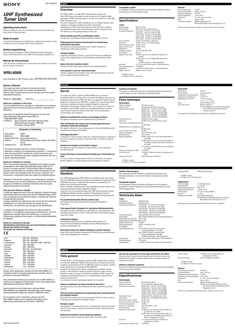
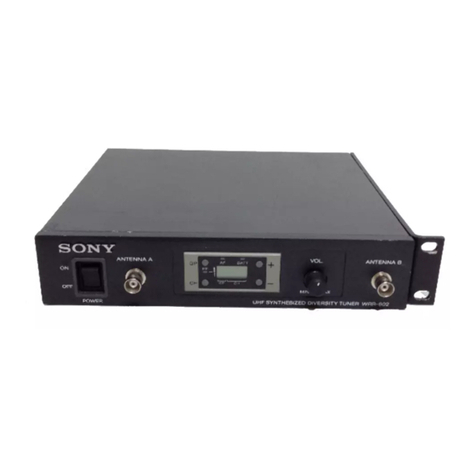
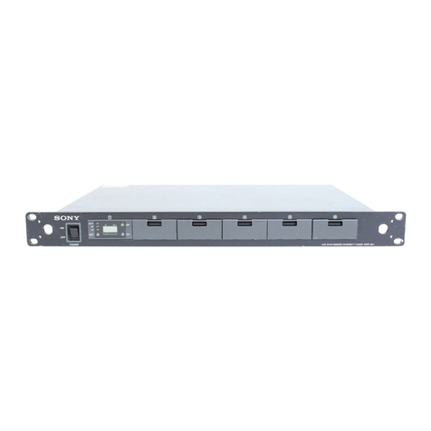
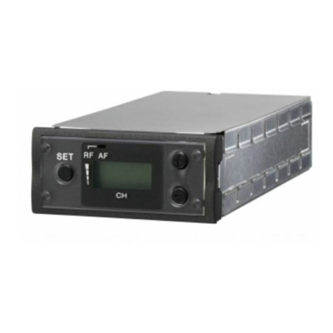
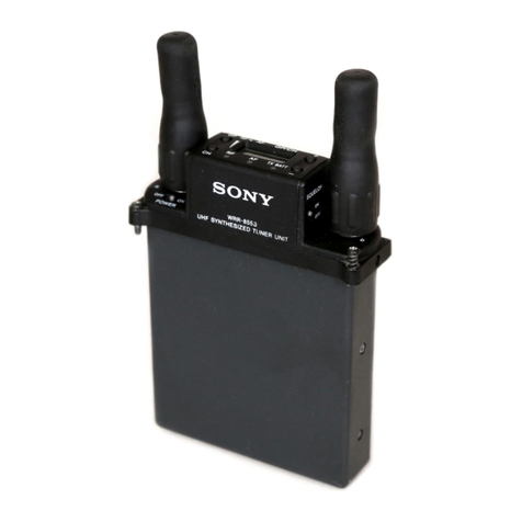
Sony WRU-806B User manual

UHF SYNTHESIZED TUNER UNIT
WRU-806B
SERVICE MANUAL
2nd Edition
Serial No. 104001 and Higher: WRU-806B (U30)
Serial No. 104001 and Higher: WRU-806B (U42)
Serial No. 421001 and Higher: WRU-806B (CE38)

WRU-806B
!WARNING
This manual is intended for qualified service personnel only.
To reduce the risk of electric shock, fire or injury, do not perform any servicing other than that
contained in the operating instructions unless you are qualified to do so. Refer all servicing to
qualified service personnel.
!WARNUNG
Die Anleitung ist nur für qualifiziertes Fachpersonal bestimmt.
Alle Wartungsarbeiten dürfen nur von qualifiziertem Fachpersonal ausgeführt werden. Um die
Gefahr eines elektrischen Schlages, Feuergefahr und Verletzungen zu vermeiden, sind bei
Wartungsarbeiten strikt die Angaben in der Anleitung zu befolgen. Andere als die angegeben
Wartungsarbeiten dürfen nur von Personen ausgeführt werden, die eine spezielle Befähigung
dazu besitzen.
!AVERTISSEMENT
Ce manual est destiné uniquement aux personnes compétentes en charge de l’entretien. Afin
de réduire les risques de décharge électrique, d’incendie ou de blessure n’effectuer que les
réparations indiquées dans le mode d’emploi à moins d’être qualifié pour en effectuer d’autres.
Pour toute réparation faire appel à une personne compétente uniquement.

1
WRU-806B
Table of Contents
Manual Structure
Purpose of this manual ................................................................. 3
Related manuals ........................................................................... 3
1. Service Overview
1-1. Boards Location .............................................................. 1-1
1-2. WRU-806B Removal ...................................................... 1-1
1-3. WRU-806B Checking ..................................................... 1-1
1-4. Error Messages ............................................................... 1-2
1-5. Setting / Release of Muting Function ............................. 1-2
1-6. Lead-free Solder ............................................................. 1-2
2. Electrical Alignment
2-1. Preparation ...................................................................... 2-1
2-1-1. Equipment and Tools ............................................2-1
2-2. Adjustments .................................................................... 2-2
2-2-1. Muting Level and RF Level Adjustment ............... 2-3
2-2-2. Output Level Adjustment ......................................2-5
2-2-3. Overall Characteristics Check ............................... 2-7
3. Spare Parts
3-1. Notes on Repair Parts ..................................................... 3-1
3-2. Exploded Views .............................................................. 3-2
3-3. Electrical Parts List ......................................................... 3-3
3-4. Supplied Accessories .................................................... 3-21
4. Block Diagrams
4-1. Circuit Description .......................................................... 4-1
4-2. CPU Pin Description .......................................................4-2
4-2-1. Pin Description of CPU (IC601 on RF-155
Board) .................................................................... 4-2
4-3. Overall Block Diagrams .................................................4-5
Overall ............................................................................ 4-5
5. Board Layouts
DP-476 ............................................................................ 5-1
RF-155 ............................................................................ 5-1
6. Schematic Diagrams
DP-476 ............................................................................ 6-1
RF-155 ............................................................................ 6-2


3
WRU-806B
Purpose of this manual
This manual describes the information items that premise the service based on the
components parts assuming use of system and service engineers.
Related manuals
The following manuals are available in this model.
If this manual is required, please contact your local Sony Sales Office/Service
Center.
..
..
.Instruction Manual (Supplied with units)
This manual is necessary for application and operation of units.
Manual Structure


1-1
WRU-806B
Section 1
Service Overview
1-1. Boards Location
1-2. WRU-806B Removal
For removing a WRU-806B from the MB-X6, refer to “In-
stalling the tuner units” in the Operating Instructions.
1-3. WRU-806B Checking
The following procedures describe how to prove WRU-
806B (repair unit) whether it needs to be repaired or not.
Equipment Required : MB-X6 (quality unit)
WRU-806B (quality unit)
(1) Install the repair WRU-806B to be examined in a quali-
ty MB-X6.
(2) Check the fault with a quality MB-X6.
.If there is a fault, WRU-806B (repair unit) is defective.
Check the WRU-806B then fix a faulty section, and
perform “2. Electrical Alignment”.
.If there is no fault found on the MB-X6, repairing
WRU-806B is no longer defective. Thus the repairing
MB-X6, other than WRU-806B, is defective.
DP-476 board
RF-155 board

1-2 WRU-806B
1-4. Error Messages
The following error messages will appear if an error is detected by the built-in self diagnostics function of the WRU-806B
installed in the MB-X6.
Error Massage Comments Countermeasure
Err 01 An error occurs in EEPROM data. Take both of the following remedial measures.
.
Write the frequency data that corresponds to the desired destination
location, into EEPROM.
.
Perform the RF squelch adjustment and the RF level indicator adjustment.
(Refer to Section 2. Electrical Alignment).
Err 02 PLL synthesizer circuit failed Malfunction of WRU-806B.
Check the WRU-806B then fix a faulty section, and perform “2. Electrical Alignment”.
NO TONE The tone signal is present, or audio Make sure that the transmitter is turned on. If it is, then the problem lies in
signal output is muted because the the transmitter’s tone signal generator or the tuner’s tone squelch circuit.
receiver received a tone signal other
.To check the characteristics, perform “2-2-3. Overall Characteristic Confirmation”.
than 32.768 kHz signal. If there are out of characteristics, tuner unit may defect.
.
Check the WRU-806B then fix a faulty section, and perform “2. Electrical
Alignment”.
n
If you are using a WRT-810A wireless microphone, a “NO TONE”message
appears when you turn off the AF switch, but this is normal.
1-5. Setting / Release of Muting Function
Set or release the following functions by operating the button on the front panel of the WRU-806B installed in the MB-X6.
n
The muting function can be set and released separately for tuner [1] to [6] . (Tuner [1] to [6] ; when WRU-806B installed
in the MB-X6.)
Function Setting / Release
.Muting OFF by RF signal input level Releasing the muting function: When pressing the “GP”and “CH”buttons, turn ON the
.Muting OFF by tone squelch POWER switch.
.Muting OFF by noise squelch Setting the muting function (Normal operation mode):Turn OFF the POWER switch.
Default Factory Setting : Setting the muting function
1-6. Lead-free Solder
Boards requiring use of unleaded solder are printed with a lead free mark (LF) indicating the solder contains no lead.
(Caution: Some printed circuit boards may not come printed with the lead free mark due to their particular size.)
: LEAD FREE MARK
m
.Be sure to use the unleaded solder for the printed circuit board printed with the lead free mark.
.The unleaded solder melts at a temperature about 40 dC higher than the ordinary solder, therefore, it is recommended to
use the soldering iron having a temperature regulator.
.The ordinary soldering iron can be used but the iron tip has to be applied to the solder joint for a slightly longer time. The
printed pattern (copper foil) may peel away if the heated tip is applied for too long, so be careful.
2-1
WRU-806B
Section 2
Electrical Alignment
2-1. Preparation
2-1-1. Equipment and Tools
Equipment
Name Specifications Model name
Signal generator Frequency : 100 kHz to 990 MHz HEWLETT PACKARD 8656B or equivalent
Spectrum analyzer Frequency : 10 kHz to 5 GHz ADVANTEST TR4173 or equivalent
DC voltmeter (Multi meter) Effective digits : 4 digits _
Audio analyzer Frequency : 10 Hz to 100 kHz HEWLETT PACKARD 8903B equivalent
RF millivoltmeter Frequency : 10 kHz to 1 GHz MEGURO MV-19B, C (with 50 Ztermination prove chip
MP-3109) or equivalent
Level meter Frequency : 20 Hz to 100 kHz _
Noise meter Frequency : 10 Hz to 500 kHz MEGURO MN-445B or equivalent
Filter (included) : A weighted filter
Tracking generator Frequency : 100 kHz to 2 GHz ADVANTEST TR4153A or equivalent
Function generator 32.768 kHz (and 32.782 kHz) ±1 Hz HEWLETT PACKARD 8904A or equivalent
signal (sine wave) can be generated.
Microphone amplifier Gain : 0 dB to 70 dB _
(with A weighted filter)
Oscilloscope Frequency : DC to 30 MHz _
Tools
Name Part No. Remarks
Adjuster (0.4 x 1.3 mm) 7-721-052-81 For adjustment
DC cut fixture _Refer to “How to make DC cut fixture”
91 Zmetal film resistor 1-214-609-00
MB-X6 _Tuner Base Unit
How to make DC cut fixture
Required parts
BNC-J connector; 1 (Part No. 1-562-261-21)
BNC-P connector; 1 (Part No. 1-560-257-11)
Ceramic capacitor 0.001 uF ; 1 (Part No. 1-161-456-00)
BNC-J connector
(1-562-261-21)
Ceramic capacitor
0.001uF 50 V (1-161-456-00)
Cut Plated wire (0.6 to 0.8 ø)
2 mm
3mm
BNC-P connector
(1-560-257-11)
Solder

2-2 WRU-806B
2-2. Adjustments
This section describes the following adjustments (and
checks) required to satisfy the specifications.
Adjustment Item
2-2-1. Muting Level and RF Level Adjustment
2-2-2. Output Level Adjustment
2-2-3. Overall Characteristic Check
1. Output Level Check
2. S/N Check
3. Frequency Characteristic Check
4. Distortion Ratio Check
5. RF Level Indicator Check
6. AF Level Indicator/AF Indicator Check
7. Muting Level/RF Indicator Check
8. BATT Indicator Check
9. Tone Squelch Check
10. DC +9 V OUT Voltage Check
n
0 dBuVEMF = _113 dBm
(EMF = Electromotive force)
0 dBm = 1 mW at 50 Z loaded
Note on Adjustment
The RF level of the input signal (the output level of the sig-
nal generator) for adjustment is expressed as an open ended
voltage in unit dBuVEMF (0 dBu = 1 uVEMF).
The adjustment is to be performed by calibrating the output
level of the signal generator as shown below.
Calibration method
(1) Connect the RF millivoltmeter to the signal generator as
shown in the figure below.
(2) Adjust the level of the output signal from the signal gen-
erator (SSG) so that the RF millivoltmeter reads 50 mV.
The level of the output signal from the signal generator
(SSG) when RF millivoltmeter reads 50 mV shall be
specified as 100 dBuVEMF (at no load).
V
Signal generator
(SSG)
RF millivoltmeter
(set in 100 mV range)
50 Z
termination probe
Adjust the output of
the signal generator
(SSG) so that the
meter reads 50 mV.
50 mV50 Z
50 Z
OSC
100 dBu

2-3
WRU-806B
2-2-1.
Muting Level and RF Level Adjustment
n
Perform the adjustment with the WRU-806B installed in
the MB-X6.
Perform this adjustment when Muting levels deviate from
the specification.
This adjustment is performed automatically by the learning
function of the WRU-806B RSSI learning.
Preparation
Before the adjustments, turn off the POWER switch of the
MB-X6, and perform the following.
1. Remove the case cover of the MB-X6.
2. Remove the upper side case lid of the tuner unit
(WRU-806B to be adjusted), and insert the tuner unit
(WRU-806B) to the Tuner [1] slot of the MB-X6.
Equipment and Tools
.Tuner base unit MB-X6
.Signal generator
.DC cut fixture (Refer to “How to make DC cut fixture”.)
Connection
Procedure
Step 1 : Preparation
Set the signal generator as follows :
Signal generator setting
FREQUENCY (carrier frequency) :
CE38 model ; 607.000 MHz
U30 model ; 567.000 MHz
U42 model ; 639.000 MHz
RF OUTPUT (Output level) : 35 duVEMF (= _78 dBm)
MODULATION (Modulation frequency) :
OFF (No modulation)
Step 2 : Adjustment
n
The adjustment procedures describe that the WRU-806B
(to be adjusted) is installed into the Tuner [1] slot on the
MB-X6.
(1) Connect the signal generator to the ANTENNA A IN
connector with DC cut fixture.
(2) Turn OFF the MB-X6 POWER switch.
(3) Set the RF OUTPUT (output level) of the signal genera-
tor to the OFF.
(4) While pressing the S601 switch on the RF-155 board
(WRU-806B, Tuner [1]), turn on the MB-X6 POWER
switch.
n
Operations in steps 1 and 2 below are also available in-
stead of step (4) above.
1. Turn on the POWER switch while pressing the
“CH", “+”, and “_”buttons on the front panel si-
multaneously.
2. Press the “CH", “+”, and “_”buttons in this order
while all items are displayed on the LCD.
(5) Indication on LCD (WRU-806B, Tuner [1]) appears as
follows :
LCD :
(6) Set the RF OUTPUT (output level) of the signal genera-
tor to the ON.
A C1 L
(A C1 L)
A
1 2 3 4 5 6
Signal
generator
DC cut fixture
ANTENNA B IN
MB-X6
Tuner slot
DC cut fixture
ANTENNA A IN
S601
RF-155 board
Tuner unit
(WRU-806B)

2-4 WRU-806B
(7) Check first that indication “L”of “AC1L”on the LCD
(WRU-806B, Tuner [1]) has disappeared, and then
press the “CH”button on the front panel (WRU-806B,
Tuner [1]).
n
If the “L”indication does not disappear from the LCD
(on Aarea: refer to the previous procedure (5) (when
the RF input level is lower than the reference level) or
“H”is displayed (when the RF input level is higher than
the reference level), perform the following adjustment.
1Check the RF output level and frequency of the sig-
nal generator (perform re-setting if necessary), and
repeat from procedure (1).
2If the above conditions (the “L”indication does not
disappear, or “H”is displayed) remain even after re-
adjustment, it is necessary to check the WRU-806B
Tuner Unit.
(8) Indication on the LCD (WRU-806B, Tuner [1]) ap-
pears as follows :
LCD :
(9) Set the FREQUENCY (carrier frequency) of the signal
generator as follows :
FREQUENCY (carrier frequency) :
CE38 model ; 618.000 MHz
U30 model ; 578.000 MHz
U42 model ; 650.000 MHz
(10)Check first that indication “L”of “AC2L”on the LCD
(WRU-806B, Tuner [1]) has disappeared, and then
press the “CH”button on the front panel (WRU-806B,
Tuner [1]).
(11)Indication on the LCD (Tuner [1]) appears as follows :
LCD :
(12)Set the FREQUENCY (carrier frequency) of the signal
generator as follows :
FREQUENCY (carrier frequency) :
CE38 model ; 629.000 MHz
U30 model ; 589.000 MHz
U42 model ; 661.000 MHz
(13) Check first that indication “L”of “AC3L”on the LCD
(WRU-806B, Tuner [1]) has disappeared, and then press the
“CH”button on the front panel (WRU-806B, Tuner [1]).
(14)Connect the signal generator to the ANTENNA B IN
connector with DC cut fixture.
(15)Indication on LCD (WRU-806B, Tuner [1]) appears as
follows :
LCD :
(16)Set the FREQUENCY (carrier frequency) of the signal
generator as follows :
FREQUENCY (carrier frequency) :
CE38 model ; 607.000 MHz
U30 model ; 567.000 MHz
U42 model ; 639.000 MHz
(17) Check first that indication “L”of “BC1L”on the LCD
(WRU-806B, Tuner [1]) has disappeared, and then press the
“CH”button on the front panel (WRU-806B, Tuner [1]).
(18)Indication on the LCD (WRU-806B, Tuner [1]) ap-
pears as follows :
LCD :
(19)Set the FREQUENCY (carrier frequency) of the signal
generator as follows :
FREQUENCY (carrier frequency) :
CE38 model ; 618.000 MHz
U30 model ; 578.000 MHz
U42 model ; 650.000 MHz
(20)Check first that indication “L”of “BC2L”on the LCD
(WRU-806B, Tuner [1]) has disappeared, and then
press the “CH”button on the front panel (WRU-806B,
Tuner [1]).
(21)Indication on the LCD (WRU-806B, Tuner [1]) ap-
pears as follows :
LCD :
A C2 L
(
A C2 L
)
A C3 L
(
A C3 L
)
B C1 L
(B C1 L)
B C2 L
(B C2 L)
B C3 L
(B C3 L)

2-5
WRU-806B
(22)Set the FREQUENCY (carrier frequency) of the signal
generator as follows :
FREQUENCY (carrier frequency) :
CE38 model ; 629.000 MHz
U30 model ; 589.000 MHz
U42 model ; 661.000 MHz
(23)Check first that indication “L”of “BC3L”on the LCD
(WRU-806B, Tuner [1]) has disappeared, and then
press the “CH”button on the front panel (WRU-806B,
Tuner [1]).
(24)Transit from indication “BACKUP”to indication “FIN-
ISH”, and then indication on the LCD (WRU-806B,
Tuner [1]) appears as follows :
LCD :
Adjustment is completed. (Normal operation mode)
2-2-2. Output Level Adjustment
n
Perform the adjustment with the WRU-806B installed in
the MB-X6.
Perform this adjustment when the TUNER OUTPUT levels
deviate from the specification.
Preparation
Before the adjustments, turn off the POWER switch of the
MB-X6, and perform the following.
1. Remove the case cover of the MB-X6.
2. Remove the upper side case lid of the tuner unit (WRU-
806B to be adjusted), and insert the tuner unit (WRU-
806B) to the Tuner [1] slot of the MB-X6.
Equipment and Tools
.Tuner base unit MB-X6
.Audio analyzer (level meter, distortion meter)
.Microphone amplifier (noise meter)
.Oscilloscope
.Adjuster (0.4 x1.3 mm) : (Part No. 7-221-052-81)
.DC cut fixture (Refer to the “How to make DC cut
fixture”.)
Connection/Adjustment Location
(CE38)
.CE38 model
CE38
(U30)
.U30 model
(U42)
.U42 model
U42
U30
.
.
1 62345
Signal
generator
Microphone
amplifier
Audio
analyzer
DC cut fixture
ANTENNA A IN
Oscilloscope
DC cut fixture
ANTENNA B IN
MB-X6
Tuner slot
600Z
balance
input
RV402 RV401
Tuner unit (WRU-806B)
TUNER
OUTPUT 1
RF-155 board

2-6 WRU-806B
Switch and Control Setting
WRU-806B Front panel (Tuner [1])
Channel setting :
CE38 model ; Group 00, 3932 channel (618.000 MHz)
U30 model ; Group 00, 3201 channel (578.125 MHz)
U42 model ; Group 00, 4401 channel (650.125 MHz)
Muting : OFF
MB-X6 Rear panel
ATT (ANTENNA A, B) switch : 0 dB
Procedure
Step 1 : Preparation
Set the signal generator as follows :
Signal generator setting
FREQUENCY (carrier frequency) :
CE38 model ; 618.000 MHz
U30 model ; 578.125 MHz
U42 model ; 650.125 MHz
RF OUTPUT (Output level) : 60 dBuVEMF
(= _53 dBm)
MODULATION (Modulation frequency) ; 1 kHz
DEVIATION (Frequency deviation) ; ±5 kHz
Step 2 : Adjustment
n
The adjustment procedures describe that the WRU-806B
(to be adjusted) is installed into the Tuner [1] slot on the
MB-X6.
(1) Connect the audio analyzer to the TUNER OUTPUT 1
connector via microphone amplifier.
(2) Connect the signal generator to the ANTENNA A IN
connector with DC cut fixture.
(3) Adjustment (ANTENNA A IN side adjustment)
Specification : Output level (level meter indication
level) = _21 dBm ±0.5 dB (at 600 Z
loaded)
Adjustment : 1RV402/RF-155 board (WRU-806B)
(4) Connect the signal generator to the ANTENNA B IN
connector with DC cut fixture.
(5) Adjustment (ANTENNA B IN side adjustment)
Specification : Output level (level meter indication
level) = _21 dBm ±0.5 dB (at 600 Z
loaded)
Adjustment : 1RV401/RF-155 board (WRU-806B)
n
The output level difference between the ANTENNA A
side and the ANTENNA B side should be within 0.3 dB.
Step 3 :
After completing adjustment, turn off the MB-X6 power
switch and perform the followings.
(1) Remove the tuner unit WRU-806B to be adjusted from
the MB-X6.
(2) Attach the upper side case lid to the tuner unit WRU-
806B.

2-7
WRU-806B
2-2-3. Overall Characteristics Check
n
Perform the check with the WRU-806B installed in the
MB-X6.
Perform the overall characteristics check according to the
following procedure.
Procedure
1. Output level check
↓
2. S/N check
↓
3. Frequency characteristic check
↓
4. Distortion check
↓
5. RF Level indicator check
↓
6. AF Level indicator/AF indicator check
↓
7. Muting level/RF indicator check
↓
8. BATT indicator check
↓
9. Tone squelch check
↓
10. DC +9 V OUT voltage check
Equipment and Tools
.Tuner base unit MB-X6
.Signal generator
.Audio analyzer
.Microphone amplifier (noise meter) with A-weighted
filter
.Function generator
.Oscilloscope
.DC current meter
.DC cut fixture (Refer to “How to make DC cut fixture”.)
Connection
1. Output Level Check
Procedure
n
The checking procedures describe that the WRU-806B (to
be adjusted) is installed into the Tuner [1] slot on the MB-
X6.
(1) Set the MB-X6 as follows :
WRU-806B Front panel (Tuner [1])
Channel setting :
CE38 model ; Group 00, 3932 channel (618.000 MHz)
U30 model ; Group 00, 3201 channel (578.125 MHz)
U42 model ; Group 00, 4401 channel (650.125 MHz)
Muting : OFF
Rear panel
ATT (ANTENNA A, B IN) switch : 0 dB
OUTPUT LEVEL switch : _20 dBm (LINE)
(2) Connect the audio analyzer to the TUNER OUTPUT 1
connector via microphone amplifier.
(3) Connect the signal generator to the ANTENNA A IN
connector with DC cut fixture.
(4) Set the signal generator as follows :
FREQUENCY (carrier frequency) :
CE38 model ; 618.000 MHz
U30 model ; 578.125 MHz
U42 model ; 650.125 MHz
RF OUTPUT (Output level) : 60 dBuVEMF (= _53 dBm)
MODULATION (Modulation frequency) : 1 kHz
DEVIATION (Frequency deviation) : ±5 kHz
1 2 3 4 5 6
Signal
generator
Audio
analyzer
Microphone
amplifier
600 Z
balance
input
DC cut fixture
ANTENNA
A IN
Oscilloscope
DC cut fixture
ANTENNA B IN
MB-X6
Tuner slot
Function
generator
TUNER
OUTPUT 1

2-8 WRU-806B
(5) Check that the TUNER OUTPUT 1 connector output
level is _21 dBm ±1.5 dB (at 600 Zloaded).
(6) Connect the audio analyzer to the MIX OUTPUT con-
nector via microphone amplifier.
(7) Check that the MIX OUTPUT connector output level is
_21 dBm ±1.5 dB (at 600 Zloaded).
(8) Set the MIX OUTPUT LEVEL switch is _58 dBm
(MIC).
(9) Check that the TUNER OUTPUT 1 connector output
level is _59 dBm ±1.5 dB (at 600 Zloaded).
(10)Check that the MIX OUTPUT connector output level is
_59 dBm ±1.5 dB (at 600 Zloaded).
(11)Connect the signal generator to the ANTENNA B IN
connector, and perform the procedures (4) to (10)
above.
2. S/N Check
Procedure
n
The checking procedures describe that the WRU-806B (to
be adjusted) is installed into the Tuner [1] slot on the MB-
X6.
(1) Set the MB-X6 as follows :
WRU-806B Front panel (Tuner [1])
Channel setting:
CE38 model ; Group 00, 3932 channel (618.000 MHz)
U30 model ; Group 00, 3201 channel (578.125 MHz)
U42 model ; Group 00, 4401 channel (650.125 MHz)
Muting : OFF
Rear panel
ATT (ANTENNA A, B IN) switch : 0 dB
(2) Connect the audio analyzer to the TUNER OUTPUT 1
connector via microphone amplifier.
(3) Connect the signal generator to the ANTENNA A IN
connector with DC cut fixture.
(4) Set the signal generator as follows :
Signal generator setting
FREQUENCY (carrier frequency) :
CE38 model ; 618.000 MHz
U30 model ; 578.125 MHz
U42 model ; 650.125 MHz
RF OUTPUT (Output level) : 60 dBuVEMF (= _53 dBm)
MODULATION (Modulation frequency) : 1 kHz
DEVIATION (Frequency deviation) : ±5 kHz
(5) Read the output level of the TUNER OUTPUT 1 con-
nector (Audio analyzer indication level). This level is
specified to be 0 dB.
(6) Turn OFF the MODULATION (modulation frequency)
of the signal generator (No modulation).
(7) Check that output level of the TUNER OUTPUT 1 is
_62 dB or less (S/N is 62 dB or more with A-weighted
filter) as compared with the level of procedure (4) above.
(8) Change the RF OUTPUT (output level) of the signal
generator as shown below.
RF OUTPUT (output level) : 25 dBuVEMF (= _93 dBm)
(9) Check that output level of the TUNER OUTPUT 1 is
_50 dB or less (S/N is 50 dB or more with A-weighted
filter) as compared with the level of procedure (5)
above.
(10)Change the RF OUTPUT (output level) of the signal
generator as shown below.
RF OUTPUT (output level) : 60 dBuVEMF (=_53 dBm)
(11)Set the audio analyzer to the distortion mode.
(12)Check that distortion ratio is _45 dB or less (0.56 % or
less) with A-weighted.
(13)Connect the signal generator to the ANTENNA B IN
connector with DC cut fixture.
(14)Perform the procedures (4) through (12) above.
(15)Set the channel and FREQUENCY (carrier frequency)
of the signal generator as shown 1and 2below.
Perform the procedures (1) to (14) above, for each chan-
nel setting (1and 2).
1Channel setting :
CE38 model ; Group 00, 3801 channel (606.125 MHz)
U30 model ; Group 00, 3001 channel (566.125 MHz)
U42 model ; Group 00, 4201 channel (638.125 MHz)
Signal generator setting :
FREQUENCY (carrier frequency)
CE38 model ; 606.125 MHz
U30 model ; 566.125 MHz
U42 model ; 638.125 MHz
2Channel setting :
CE38 model ; Group 00, 4063 channel (629.875 MHz)
U30 model ; Group 00, 3347 channel (589.875 MHz)
U42 model ; Group 00, 4547 channel (661.875 MHz)
Signal generator setting:
FREQUENCY (carrier frequency):
CE38 model ; 629.875 MHz
U30 model ; 589.875 MHz
U42 model ; 661.875 MHz

2-9
WRU-806B
3. Frequency Characteristic Check
Procedure
n
The checking procedures describe that the WRU-806B (to
be adjusted) is installed into the Tuner [1] slot on the MB-
X6.
(1) Set the MB-X6 as follows :
WRU-806B Front panel (Tuner [1])
Channel setting :
CE38 model ; Group 00, 3932 channel (618.000 MHz)
U30 model ; Group 00, 3201 channel (578.125 MHz)
U42 model ; Group 00, 4401 channel (650.125 MHz)
Muting: OFF
Rear panel
ATT (ANTENNA A, B) switch : 0 dB
(2) Connect the audio analyzer to the TUNER OUTPUT 1
connector via microphone amplifier.
(3) Connect the signal generator to the ANTENNA A IN
connector with DC cut fixture.
(4) Set the signal generator as follows :
Signal generator setting
FREQUENCY (carrier frequency) :
CE38 model ; 618.000 MHz
U30 model ; 578.125 MHz
U42 model ; 650.125 MHz
RF OUTPUT (Output level) : 60 dBuVEMF (= _53 dBm)
MODULATION (Modulation frequency) : 1 kHz
DEVIATION (Frequency deviation) : ±12 kHz
(5) Read the output level of the TUNER OUTPUT 1
(indication of the audio analyzer).
This level is specified to be 0 dB.
(6) Change the MODULATION (modulation frequency) of
the signal generator as follows, and check the output
level with respect to the output level under the proce-
dure (3) is set also as follows.
n
40 Hz and 18 kHz modulation frequency must be set by
using the function generator.
MODULATION frequency TUNER OUTPUT 1 connector
of signal generator output level
40 Hz _1.5 ±1.0 dB
18 kHz _35.0 ±3.0 dB
(7) Connect the signal generator to the ANTENNA B IN
connector with DC cut fixture, and perform the proce-
dures (4), (5) and (6).
4. Distortion Ratio Check
Procedure
n
The checking procedures describe that the WRU-806B (to
be adjusted) is installed into the Tuner [1] slot on the MB-
X6.
(1) Set the MB-X6 as follows :
WRU-806B Front panel (Tuner [1])
Channel setting:
CE38 model ; Group 00, 3932 channel (618.000 MHz)
U30 model ; Group 00, 3201 channel(578.125 MHz)
U42 model ; Group 00, 4401 channel(650.125 MHz)
Muting : OFF
Rear panel
ATT (ANTENNA A, B) switch : 0 dB
(2) Connect the audio analyzer to the TUNER OUTPUT 1
connector via microphone amplifier.
(3) Connect the signal generator to the ANTENNA A IN
connector with DC cut fixture.
(4) Set the signal generator as follows :
Signal generator setting
FREQUENCY (carrier frequency) :
CE38 model ; 618.000 MHz
U30 model ; 578.125 MHz
U42 model ; 650.125 MHz
RF OUTPUT (Output level) : 60 dBuVEMF (= _53 dBm)
MODULATION (Modulation frequency) : 1 kHz
DEVIATION (Frequency deviation) : ±40 kHz
(5) Set the audio analyzer to the distortion mode, and check
that the distortion ratio is less than 1.0 %.
(6) Change the MODULATION (modulation frequency) of
the signal generator as shown below.
MODULATION (modulation frequency) : 10 kHz
(Note ; 10 kHz modulation frequency must be set by
using the function generator.)
Check that the distortion ratio is less than 5.0 %.
(7) Connect the signal generator to the ANTENNA B IN
connector with DC cut fixture, and perform the proce-
dures (4) through (6) above.

2-10 WRU-806B
(8) Set the channel setting (Tuner [1]) and FREQUENCY
(carrier frequency) of the signal generator as shown 1
and 2below.
Perform the procedures (1) to (7) above, for each chan-
nel setting (1and 2).
1Channel setting :
CE38 model ; Group 00, 3801 channel (606.125 MHz)
U30 model ; Group 00, 3001 channel (566.125 MHz)
U42 model ; Group 00, 4201 channel (638.125 MHz)
Signal generator setting :
FREQUENCY (carrier frequency)
CE38 model ; 606.125 MHz
U30 model ; 566.125 MHz
U42 mode ; 638.125 MHz
2Channel setting :
CE38 model ; Group 00, 4063 channel (629.875 MHz)
U30 model ; Group 00, 3347 channel (589.875 MHz)
U42 model ; Group 00, 4547 channel (661.875 MHz)
Signal generator setting :
FREQUENCY (carrier frequency) :
CE38 model ; 629.875 MHz
U30 model ; 589.875 MHz
U42 model ; 661.875 MHz
5. RF Level Indicator/RF Indicator Check
Procedure
n
The checking procedures describe that the WRU-806B (to
be adjusted) is installed into the Tuner [1] slot on the MB-
X6.
(1) Set the MB-X6 as follows :
WRU-806B Front panel (Tuner [1])
Channel setting :
CE38 model ; Group 00, 3932 channel (618.000 MHz)
U30 model ; Group 00, 3201 channel (578.125 MHz)
U42 model ; Group 00, 4401 channel (650.125 MHz)
Muting: ON
Rear panel
ATT (ANTENNA A, B) switch : 0 dB
(2) Connect the signal generator to the ANTENNA A IN
connector with DC cut fixture.
(3) Set the signal generator as follows :
Signal generator setting
FREQUENCY (carrier frequency) :
CE38 model ; 618.000 MHz
U30 model ; 578.125 MHz
U42 model ; 650.125 MHz
RF OUTPUT (Output level) : 0 dBuVEMF (= _113 dBm)
MODULATION (Modulation frequency) : 1 kHz
DEVIATION (Frequency deviation) : ±5 kHz
(4) Increase gradually the output level from the signal gen-
erator, and check that the output level of the signal gen-
erator is as follows when the RF input level indicator
(Tuner [1]) lights.
RF level indicator (green) Signal generator output level
lights in of Tuner [1][1]
[1][1]
[1]
Lighting
LCD:
25 dBuVEMF ±5 dB
Lighting
LCD:
35 dBuVEMF ±5 dB
Lighting
LCD:
45 dBuVEMF ±5 dB
Lighting
LCD:
55 dBuVEMF ±5 dB
(5) Connect the signal generator to the ANTENNA B IN
connector with DC cut fixture, and perform the proce-
dures (3) and (4) above.

2-11
WRU-806B
(6) Set the channel setting (Tuner [1]) and FREQUENCY
(carrier frequency) of the signal generator as shown 1
and 2below.
Perform the procedures (1) through (5) above, for each
channel setting (1and 2).
1Channel setting :
CE38 model ; Group 00, 3801 channel (606.125 MHz)
U30 model ; Group 00, 3001 channel (566.125 MHz)
U42 model ; Group 00, 4201 channel (638.125 MHz)
Signal generator setting :
FREQUENCY (carrier frequency)
CE38 model ; 606.125 MHz
U30 model ; 566.125 MHz
U42 model ; 638.125 MHz
2Channel setting :
CE38 model ; Group 00, 4063 channel (629.875 MHz)
U30 model ; Group 00, 3347 channel (589.875 MHz)
U42 model ; Group 00, 4547 channel (661.875 MHz)
Signal generator setting :
FREQUENCY (carrier frequency) :
CE38 model ; 629.875 MHz
U30 model ; 589.875 MHz
U42 model ; 661.875 MHz
6. AF Level Indicator/AF Indicator Check
Procedure
n
The checking procedures describe that the WRU-806B (to
be adjusted) is installed into the Tuner [1] slot on the MB-
X6.
(1) Set the MB-X6 as follows :
WRU-806B Front panel (Tuner [1])
Channel setting :
CE38 model ; Group 00, 3932 channel (618.000 MHz)
U30 model ; Group 00, 3201 channel (578.125 MHz)
U42 model ; Group 00, 4401 channel (650.125 MHz)
Muting : OFF
Rear panel
ATT (ANTENNA A, B) switch : 0 dB
(2) Connect the signal generator to the ANTENNA A IN
connector with DC fixture.
(3) Set the signal generator as follows :
Signal generator setting
FREQUENCY (carrier frequency) :
CE38 model ; 618.000 MHz
U30 model ; 578.125 MHz
U42 model ; 650.125 MHz
RF OUTPUT (Output level) : 60 dBuVEMF (= _53 dBm)
MODULATION (Modulation frequency) :1 kHz
(4) Increase gradually DEVIATION (frequency deviation)
of the signal generator starting from ±3 kHz, and check
that the deviation of the signal generator is ±(5.0 ±1.0)
kHz with the AF indicator as follows.
DEVIATION setting AF indicator of
on signal generator Tuner [1][1]
[1][1]
[1]
±(5.0 ±1.0) kHz AF level indicator (LCD);
Lights.
AF indicator (LED);
Lights.
Less than AF level indicator (LCD);
±(5.0 ±1.0) kHz Goes out.
AF indicator (LED);
Goes out.
(5) Connect the signal generator to the ANTENNA B IN
connector with DC cut fixture, and perform the proce-
dures (3) and (4) above.
7. Muting Level/RF Indicator Check
Procedure
n
The checking procedures describe that the WRU-806B (to
be adjusted) is installed into the Tuner [1] slot on the MB-
X6.
(1) Set the MB-X6 as follows :
WRU-806B Front panel (Tuner [1] )
Channel setting :
CE38 model ; Group 00, 3932 channel (618.000 MHz)
U30 model ; Group 00, 3201 channel (578.125 MHz)
U42 model ; Group 00, 4401 channel (650.125 MHz)
Muting : ON (Normal mode)
Rear panel
ATT (ANTENNA A, B) switch : 0 dB
(2) Connect the signal generator to the ANTENNA A IN
connector with DC cut fixture.
AF
AF

2-12 WRU-806B
(3) Set the signal generator as follows :
Signal generator setting
FREQUENCY (carrier frequency) :
CE38 model ; 618.000 MHz
U30 model ; 578.125 MHz
U42 model ; 650.125 MHz
RF OUTPUT (Output level) : 60 dBuVEMF (= _53 dBm)
MODULATION (Modulation frequency) : 1 kHz
DEVIATION (Frequency deviation) : ±5 kHz
(4) Check that RF Indicator LED lights (green) and “NO
TONE”message appears on LCD (Tuner [1]).
(5) Change the RF OUTPUT (output level) of the signal
generator as shown below.
RF OUTPUT (output level) : 15 dBuVEMF (= _98 dBm)
(6) Check that RF Indicator LED goes off (green) and “NO
TONE”message disappears on LCD (Tuner [1]).
(7) Increase gradually the RF OUTPUT (output level) of
the signal generator. Check that RF OUTPUT (output
level) is 25 dBuVEMF ±5 dB at when RF Indicator lights
(green LED) and “NO TONE”message appears on
LCD (Tuner [1]).
(8) Connect the signal generator to the ANTENNA B IN
connector with DC cut fixture, and perform the proce-
dures (3) through (7) above.
(9) Set the channel setting (Tuner [1]) and FREQUENCY
(carrier frequency) of the signal generator as shown 1
and 2below.
Perform the procedures (1) to (8) above, for each
channel setting (1and 2).
1Channel setting :
CE38 model ; Group 00, 3801 channel (606.125 MHz)
U30 model ; Group 00, 3001 channel (566.125 MHz)
U42 model ; Group 00, 4201 channel (638.125 MHz)
Signal generator setting :
FREQUENCY (carrier frequency)
CE38 model ; 606.125 MHz
U30 model ; 566.125 MHz
U42 model ; 638.125 MHz
2Channel setting :
CE38 model ; Group 00, 4063 channel (629.875 MHz)
U30 model ; Group 00, 3347 channel (589.875 MHz)
U42 model ; Group 00, 4547 channel (661.875 MHz)
Signal generator setting :
FREQUENCY (carrier frequency) :
CE38 model ; 629.875 MHz
U30 model ; 589.875 MHz
U42 model ; 661.875 MHz
8. BATT (Battery) Indicator Check
Procedure
n
The checking procedures describe that the WRU-806B (to be
adjusted) is installed into the Tuner [1] slot on the MB-X6.
(1) Set the MB-X6 as follows :
WRU-806B Front panel (Tuner [1])
Channel setting :
CE38 model ; Group 00, 3932 channel (618.000 MHz)
U30 model ; Group 00, 3201 channel (578.125 MHz)
U42 model ; Group 00, 4401 channel (650.125 MHz)
Muting : ON (Normal mode)
Rear panel
ATT (ANTENNA A, B) switch : 0 dB
(2) Connect the signal generator to the ANTENNA A IN
connector with DC cut fixture.
(3) Set the signal generator as follows :
Signal generator setting
FREQUENCY (carrier frequency) :
CE38 model ; 618.000 MHz
U30 model ; 578.125 MHz
U42 model ; 650.125 MHz
RF OUTPUT (Output level) : 60 dBuVEMF (= _53 dBm)
MODULATION (Modulation frequency) : 32.782 kHz
(32.782 kHz must be set by connecting Function generator)
DEVIATION (Frequency deviation) : ±2.1 kHz
(4)
Turn on and off the MODULATION (modulation fre-
quency) of the signal generator as follows, and check that
BATT Indicator (Tuner [1]) change also as follows :
MODULATION setting BATT indicator of Tuner
[1][1]
[1][1]
[1]
of signal generator
ON BATT indicator (LCD) ;
Turn the signal
generator on and BATT
indicator starts blinking
after 30 seconds.
BATT indicator (LED) ;
Turn the signal
generator on and BATT
indicator starts blinking
after 30 seconds.
OFF BATT indicator (LCD) ;
Goes out.
BATT indicator (LED) ;
Goes out.
(5) Connect the signal generator to the ANTENNA B IN
connector with DC cut fixture, and perform the proce-
dures (3) and (4) above.
AF
RF
RF indicator lights.
BATT
AF
AF BATT
Other manuals for WRU-806B
2
Table of contents
Other Sony Tuner manuals

Sony
Sony ST-SA5ES User manual

Sony
Sony XT-100HD User manual

Sony
Sony WRU-806B User manual

Sony
Sony ST-S3000ES User manual

Sony
Sony WRR-800A User manual

Sony
Sony Dream Machine ICF-C743 User manual

Sony
Sony ST-S333ESG User manual

Sony
Sony WRR-861A User manual

Sony
Sony TGV-1E User manual

Sony
Sony ST-JX311 User manual