Sony WRR-800A User manual

3-860-929-21 (1)
Operating Instructions
Bedienungsanleitung
Wireless Channel Lists/Übertragungskanallisten
WRR-800A
© 1997 by Sony Corporation
D
EN
UHF Synthesized
DiversityTuner
[CE62] [CE64] [CE69]

English
WARNING
To prevent fire or shock hazard, do not expose the unit
to rain or moisture.
To avoid electrical shock, do not open the cabinet.
Refer servicing to qualified personnel only.

1
EN
English
EN
Overview ...................................................................1
Features ................................................................. 2
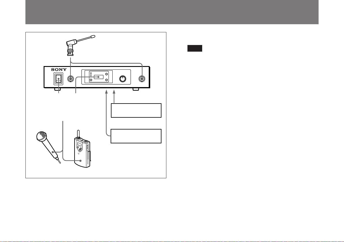
System Configuration ........................................... 3
Channel Plan ......................................................... 3
Precautions............................................................... 4
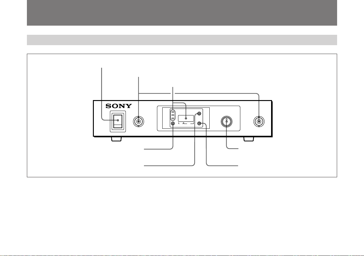
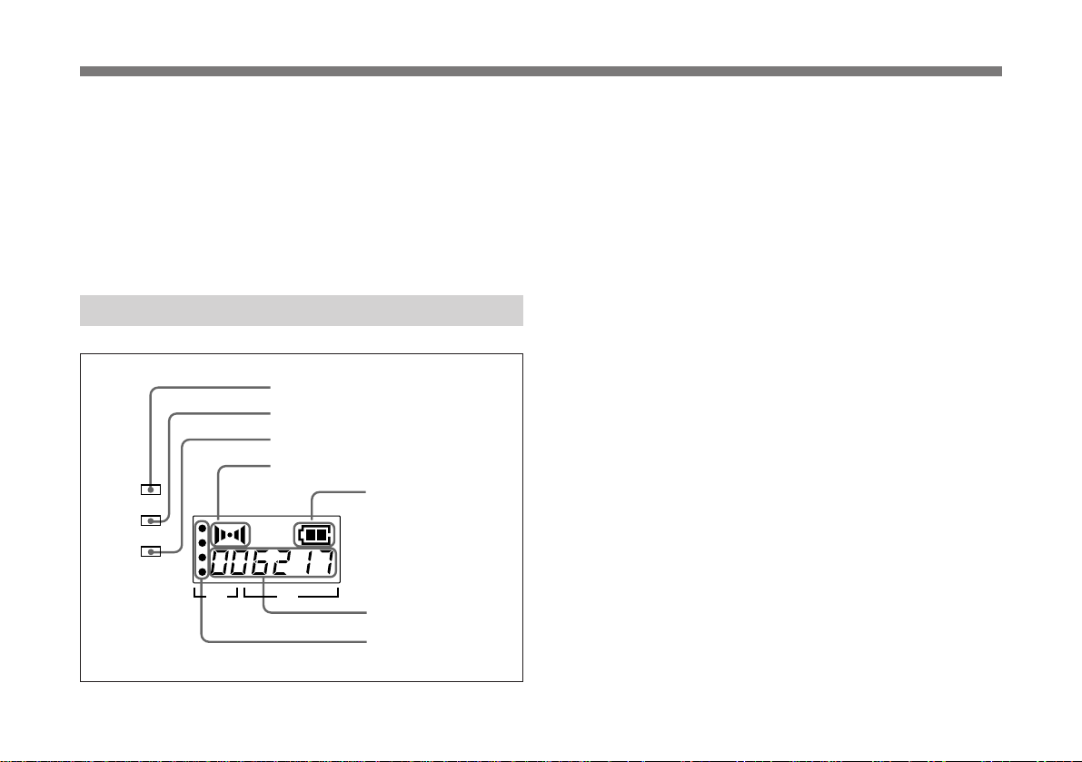
Location of Parts and Controls............................... 5
Front Panel ............................................................ 5
Display .................................................................. 6
Rear Panel ............................................................. 7
Operation ..................................................................8
Muting Functions .................................................. 9
Channel Setting........................................................ 9
Error Messages ......................................................11
Specifications......................................................... 12
The WRR-800A is a reliable UHF synthesized diversity
tuner for the 800-MHz-band Sony UHF wireless
microphone system which uses the frequency bands
allocated for UHF TV broadcasting.
This unit is designed to enable simultaneous use of multiple
channels when channels are selected according to the
channel plan.
In building up a UHF wireless microphone system, be sure
to combine a microphone/transmitter and a tuner having the
same TV channel number (62, 64 or 69).
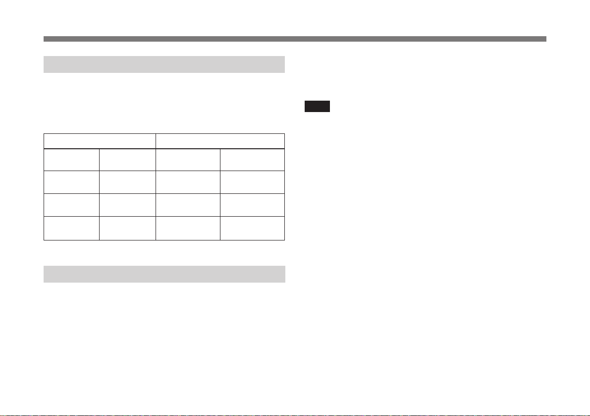
CE62 model
A 14 MHz frequency band is assigned to the WRR-800A/
CE62 model, permitting it to operate on any of 111
receiving frequencies in 125-kHz steps of Sony original
channel plan or 561 receiving frequencies in 25-kHz steps of
German User Group in the range of TV channels 62 and 63.
The selectable wireless channels and frequencies for this
model are listed pages L-2 through L-10.
CE64 model
A 14 MHz frequency band is assigned to the WRR-800A/
CE64 model, permitting it to operate on any one of 111
receiving frequencies in 125-kHz steps of Sony original
channel plan or 561 receiving frequencies in 25-kHz steps of
German User Group in the range of TV channels 64 and 65.
OverviewTable of Contents

2
EN
The selectable wireless channels and frequencies for this
model are listed on pages L-11 through L-19.
CE69 model
An 8 MHz frequency band is assigned to the WRR-800A/
CE69 model, permitting it to operate on any of 64 receiving
frequencies in 125-kHz steps of Sony original channel plan
in the range of TV channel 69 or 14 receiving frequencies in
25-kHz steps of UK General Use.
The selectable wireless channels and frequencies for this
model are listed on pages L-20 and L-21.
Features
Phase Locked Loop (PLL) synthesized system
The WRR-800A has a refined phase locked loop (PLL)
synthesizer circuit.
Preprogrammed wireless channel plan for
simultaneous multichannel operation
The WRR-800A has many preprogrammed, easily settable
channels in a simultaneous multichannel operation.
Overview
Versatile display
A liquid-crystal display provides a variety of information,
including the levels of the reception channels, RF
information and transmitter battery alarm.
Space diversity reception system
The WRR-800A provides stable signal reception with
minimum dropout.
Tone squelch circuit for noise elimination
A built-in squelch circuit eliminates noise and signal
interference when the WRR-800A is in signal reception
standby mode.
Compander system
A compander (compressor/expander) system enables
stabilized wireless transmission over a wide dynamic range.

3
EN
1) The distance depends on the operating environment and conditions.
............................................................................................................................................................................................................................................................
Frequency band Model name
TV channel Transmitter or
microphone
Frequency
(MHz)
62 WRT-800A (62)
WRT-805A (62)
800.000 to
814.000 WRR-800A (62)
WRR-801A (62)
64 816.000 to
830.000 WRT-800A (64)
WRT-805A (64) WRR-800A (64)
WRR-801A (64)
69 854.125 to
862.000 WRT-800A (69)
WRT-805A (69) WRR-800A (69)
WRR-801A (69)
Tuner
System Configuration
The unit can be used with a Sony UHF synthesized wireless
microphone or UHF synthesized transmitter among the
models listed in the table below.
Sony 800 MHz-band system models
Channel Plan
The unit stores several groups of channels. See “Overview
of Channel Plan” in the “Wireless Channel Lists” section.
Channel groups other than group 00 are designed so that all
channels of one group can be used simultaneously within the
same UHF wireless microphone system without causing
intermodulation. It is therefore recommended that you
usually use a channel group other than group 00 unless the
use of group 00 is specifically necessary.
Note
To eliminate interference or noise, please note the
following.
• Do not use two or more wireless microphones or
transmitters whose wireless channels are the same.
• If there is a TV broadcasting station nearby, to avoid
possible interference from its broadcasting, do not use that
station’s channel.
• The number of wireless microphone channels actually
usable in a multi-channel system may be smaller than the
normal capacity of that system if there is interference from
TV broadcasting or other RF signals.
• When operating two or more UHF wireless microphone
systems using the same wireless channel in the same
group, ensure that the systems are at least 100 m1) apart as
far as they are installed within sight of each other.

4
EN
Precautions
On cleaning
Clean the unit with a dry, soft cloth. Never use thinner,
benzene, alcohol or any other chemicals, since these may
damage the finish.
On operation
• The unit must be used within a temperature range of 0°C to
40°C. Avoid using the unit for extended periods at
extremely high temperatures or placing it in direct sunlight,
especially outdoors because this may damage the finish of
the case. Never install the unit on or near a heat source,
such as lighting equipment or power amplifiers.
• Avoid using in very humid or dusty places, because such
use may shorten the life of the unit.
• To avoid degradation of the signal-to-noise ratio, do not
use the unit in noisy places or in locations subject to
vibration, such as the following:
— near electrical equipment, such as motors, transformers
or dimmers
— near air conditioning equipment or places subject to
direct air flow from an air conditioner
— near public address loudspeakers
— where adjacent equipment might knock against the unit
• Switching lights on or off may produce electrical
interference over the entire frequency range. Position the
unit and the wireless microphones so that interference is
minimized.
• The unit is precisely adjusted at the factory and no
adjustment before use is necessary. Do not touch the
inside of the unit or try to repair it by yourself.

5
EN
Location of Parts and Controls
Front Panel
1POWER switch
Turns the power on and off.
2ANTENNA A, B (antenna A, B) connectors (BNC
type)
Connect the supplied antennas.
3Display
Displays the status of this unit and the groups and channels
assigned to the unit.
For details, see the following section “Display”.
4SET button
Press to change the group or channel.
ON ANTENNAA VOL. ANTENNA B
SET
GP
CH
OFF
POWER
BATT
RF
AF
MIN MAX
AF BATT
GP CH
1POWER switch
2ANTENNA A, B connectors
3Display
4SET button
5GP button
7VOL. Control
6CH button

6
EN
5GP (group) button
Press to change the group or to display frequencies.
6CH (channel) button
Press to change the channel in a group.
7VOL. (volume) control
Adjusts the volume of the tuner output.
Display
Location of Parts and Controls
1BATT (battery) indicator
5BATT (battery) indication
Indicate the condition of the wireless microphone
transmitter batteries. The indicator and indication start
flashing about one hour before the transmitter batteries go
flat.
2RF (radio frequency) indicator
7RF (radio frequency) indications
The indicator lights and the indications (dots) appear when
the antenna reception is optimal. Depending on the RF input
level, the number of dots changes.
3AF (audio frequency) indicator
4AF (audio frequency) indication
The indicator lights and the indication appears when the
audio output level is higher than the reference level.
6GP/CH (group/channel) indication
Shows the reception channel group and respective channel
number.
Pressing the GP button changes this indication to the
frequency indication.
AF BATT
GP CH
BATT
RF
AF
1BATT indicator
2RF indicator
3AF indicator
4AF indication
7RF indications
6GP/CH indication
5BATT indication

7
EN
1TUNER OUTPUT (tuner sound output) connector
(ø6.3 phone balanced (TRS))
Supplies audio signals. You can connect this to the audio
input connector of a mixer, amplifier, or similar equipment.
2DC IN 9V (9 V DC power input) connector
Connect the supplied AC power adaptor.
3Cord clamp
Attaches the cord of the AC power adaptor.
Operation
Rear Panel
TUNER OUTPUT
LINE LEVEL 0dBm
DC IN 9V
¥
1TUNER OUTPUT connector
3Cord clamp
2DC IN 9V connector

8
EN
1Connect the supplied antennas and make the antenna
tips point upward.
2Connect the supplied AC power adaptor to the DC IN
9V connector and an audio mixer or amplifier to the
TUNER OUTPUT connector.
3Turn the POWER switch on.
Note
Turn the POWER switch on after reducing the volume
of the equipment connected to the TUNER OUTPUT
connector. Otherwise, noise will be heard when the
POWER switch is turned on.
4Set the reception channel.
For details on setting the channels, see page 9.
5Turn on the wireless microphone or transmitter.
Use the wireless microphone or transmitter to which the
same channel is assigned as to this unit.
If noise is heard
Depending on the environment where the system is
installed, outside noise or radio wave may disrupt the
transmission of certain channels.
To select a channel under this circumstance, turn off the
wireless microphone or transmitter. Then select a channel at
which the RF indicator is off. (A channel free from noise or
radio wave interference is selected.) Set the same channel on
the microphone or transmitter.
+
–
5
34
1
2
ANTENNA A, B
Audio mixer, amplifier
AC power adaptor
UHF synthesized
transmitter
UHF
synthesized
wireless
microphone
DC IN 9V
TUNER OUTPUT

9
EN
Muting Functions
This unit has the following three muting functions, which
work in combination.
(1) Muting by RF input level
As sufficient S/N for the audio output may not be obtained if
no RF signal is received or the RF input level is low, the
audio output can be muted when the RF input level falls
below the muting level.
(2) Tone squelch
The audio output is obtained only when the unit receives an
RF signal which includes a specified tone signal. The audio
output is muted to eliminate noise which may be heard when
the transmitter is turned on/off or the unit receives an
interference RF signal.
(3) Noise squelch
The audio output is muted to eliminate noise which may be
heard when there is such excessive interference RF signal
that the tone squelch does not work.
Channel Setting
Here is explained channel setting for the CE62 model as an
example.
Take the following precautions to prevent interference and
noise.
• Do not simultaneously use two or more microphones and
transmitters that are set to the same channel.
• When simultaneously using two or more tuners, always set
the tuners to different channels within the same group
(other than group 00).
• Separate the reception antennas and the transmitter by
more than 3 meters.
1Turn the POWER switch on.
The message “62” appears on the display, and then the
current status of this unit is displayed.
1 2,3,4 3 4
(Continued)

10
EN
Channel Setting
GP CH GP CH
Note
Turn the POWER switch on after reducing the volume
of equipment connected to the TUNER OUTPUT
connector. Otherwise, noise will be heard when the
power is turned on.
2Press the SET button and hold it down.
The unit changes to the group and channel selection
mode.
3While holding down the SET button, press the GP
button to select a group.
Each time you press the GP button, the GP indication
changes as shown in the following figure. To change the
indication continuously, press and hold down the GP
button.
The CH indication shows the lowest frequency channel
of the selected group. For group 00, however, the
channel selected last is displayed.
Releasing the buttons automatically cancels the group
selection mode, and the currently displayed group is
selected.
For the CE64 model, the indication will cycle from
group 00 through 65. For the CE69 model, the
indication will cycle from group 00 through H.
Refer to “Overview of Channel Plan” in the “Wireless
Channel Lists” section.
4While holding down the SET button, press the CH
button to select a channel.
Similar to step 3, each time you press the CH button,
the CH indication changes in the order shown in the
group and reception channel list. (See “Wireless
Channel Lists”.)
If you press the CH button when the last channel of the
selected group is displayed, the first channel of the
group will be displayed.
GP CH GP CH
01 02 03 04 62A
63A 62E 62D 62C 62B
63D 63E 62 63
00
63B
63C

11
EN
GP CH GP CH
Meaning Remedy
Err 01
Message
An error has occurred in
the backup memory data. The memory data is
initialized. Reset the
group and channel
settings.
Contact your nearest
Sony dealer.
The PLL-synthesized
circuit has a malfunction.
Err 02
NO TONE As no tone signal is
available or a tone signal
other than 32.768 kHz is
being received, the audio
signal output is muted.
The transmitter’s tone
signal or the tuner is in
trouble. Contact your
nearest Sony dealer.
Selecting the reception channel by frequency
Press the GP button.
This changes the GP/CH indication to a frequency
indication.
To change a frequency, press the CH button while
keeping the SET button pressed. (A higher frequency
will be displayed.)
Press the GP button again to change the frequency
indication back to a GP/CH indication.
5If the desired channel or frequency is displayed, release
the SET button and CH button.
The selected channel is set.
To store the selected group and channel
Leave the indication unchanged for 5 seconds.
The group and channel set in the procedure explained above
are stored in memory.
Error Messages
Apart from the normal indications, the following error
messages may appear on the display.

12
EN
Specifications
Tuner
Reception type F3E
Circuit system Dual conversion superheterodyne
Reception frequencies
CE62 model: 800.000 to 814.000 MHz
CE64 model: 816.000 to 830.000 MHz
CE69 model: 854.125 to 862.000 MHz
Local oscillatorsCrystal controlled PLL synthesizer
Selectivity 60 dB or more (at ±250 kHz detuned)
Spurious rejection ratio
70 dB or more
Image rejection ratio
70 dB or more
Muting level 30 dBµ1)
Antenna connectors
BNC-R type (2), 50 ohms
Frequency response
100 to 15,000 Hz ±3 dB
De-emphasis 50 µsec
Signal-to-noise ratio
30 dB or more at an A-weighted RF input
level of 20 dBµ
60 dB or more at an A-weighted RF input
level of 60 dBµ
(±5 kHz deviation at 1 kHz modulation)
Distortion 1% or less (±40 kHz deviation at 1 kHz
modulation)
Tone signal frequency
32.768 kHz
Output level 0 dBm2) (±16 kHz deviation at 1 kHz
modulation)
(–20 dBm (±5 kHz deviation at 1 kHz
modulation))
Output impedance
150 ohms
Output connector
ø6.3 phone balanced (TRS)
1) 0 dBµ=1 µV
2) 0 dBm=0.775 Vrms (600 ohms loaded)
General
Power requirements
9 V DC
Current consumption
Approx. 500 mA
Operating temperature
0°C to 40°C
Storage temperature
–20°C to +55°C
Dimensions 218 ×44 ×210 mm (w/h/d)
Mass Approx. 1.6 kg
Accessories supplied
AC power adaptor (1)
Antennas (2)
Operating Instructions (1)
Design and specifications are subject to change without
notice.


Deutsch
VORSICHT
Um Feuergefahr und die Gefahr eines elektrischen Schlages
zu vermeiden, darf das Gerät weder Regen noch
Feuchtigkeit ausgesetzt werden.
Um einen elektrischen Schlag zu vermeiden, darf das
Gehäuse nicht geöffnet werden. Überlassen Sie
Wartungsarbeiten stets nur einem Fachmann.
Für Kunden in Deutschland
Dieses Produkt kann im kommerziellen und in begrenztem
Maße auch im industriellen Bereich eingesetzt werden. Dies
ist eine Einrichtung, welche die Funk-Entstörung nach
Klasse B besitzt.

1
D
D
Deutsch
Inhaltsverzeichnis
Überblick................................................................... 1
Merkmale .............................................................. 2
Bestandteile........................................................... 3
Kanalplan .............................................................. 3
Zur besonderen Beachtung ....................................4
Lage und Funktion der Teile ................................... 5
Vorderseite............................................................ 5
Display .................................................................. 6
Rückseite............................................................... 7
Betrieb....................................................................... 8
Rauschsperre ......................................................... 9
Kanalwahl .................................................................9
Fehlermeldungen ...................................................11
Technische Daten ..................................................12
Überblick
Der UHF-Tuner WRR-800A arbeitet im 800-MHz-TV-Band
und dient zum Empfang der Signale eines Sony UHF-
Mikrofonsystems. Dank dem PLL-Synthesizer und der
Diversity-Funktion gewährleistet der Tuner einen
zuverlässigen Empfang. Das Kanalraster ist so ausgelegt,
daß ein simultaner Betrieb auf mehreren Kanälen möglich
ist.
Achten Sie bei der Zusammenstellung eines UHF-
Mikrofonsystems darauf, daß Mikrofon/Sender und Tuner
dieselbe TV-Kanalnummer (62, 64 oder 69) besitzen.
Modell CE62
Die Kanäle des Modells WRR-801A/CE62 erstrecken sich
über einen 14 MHz breiten Frequenzbereich. Dieses Modell
besitzt 111 Empfangsfrequenzen mit 125-kHz-Raster (nach
Sony Kanalplan) bzw. 561 Empfangsfrequenzen mit 25-
kHz-Raster im Bereich der TV-Kanäle 62 und 63 (nach der
deutschen Benutzergruppe).
Die wählbaren Kanäle und die Frequenzen dieses Modells
finden Sie in den Tabellen von Seite L-2 bis L-10.
Modell CE64
Die Kanäle des Modells WRR-801A/CE64 erstrecken sich
über einen 14 MHz breiten Frequenzbereich. Dieses Modell
besitzt 111 Empfangsfrequenzen mit 125-kHz-Raster (nach
Sony Kanalplan) bzw. 561 Empfangsfrequenzen mit 25-
kHz-Raster im Bereich der TV-Kanäle 64 und 65 (nach der
deutschen Benutzergruppe).

2
D
Die wählbaren Kanäle und die Frequenzen dieses Modells
finden sie in den Tabellen von Seite L-11 bis L-19.
Modell CE69
Die Kanäle des Modells WRR-801A/CE69 erstrecken sich
über einen 8 MHz breiten Frequenzbereich.
Dieses Modell besitzt 64 Empfangsfrequenzen mit 125-kHz-
Raster im TV-Kanal 69 (nach Sony Kanalplan) bzw. 14
Empfangsfrequenzen mit 25-kHz-Raster (nach Kanaplan für
allgemeine Verwendung in Gro·britannien).
Die wählbaren Kanäle und die Frequenzen dieses Modells
funden Sie in den Tabellen von Seite L-20 und L-21.
Merkmale
PLL-Synthesizersystem (Phase Locked Loop)
Der WRR-800A ist mit einem modernen PLL-Synthesizer-
Schaltkreis ausgestattet.
Fest gespeicherter Kanalplan für simultanen
Mehrkanalbetrieb
Eine große Anzahl von Kanälen ist im WRR-800A fest
einprogrammiert. Mit den Bedienungselementen auf der
Vorderseite können diese Kanäle bequem eingestellt
werden.
Informatives Display
Das Flüssigkristalldisplay zeigt verschiedene Informationen
wie beispielsweise die Empfangs-Feldstärke und eine
Warnmeldung bei schwacher Sendebatterie an.
Diversity-Funktion für stabilen Empfang in großen
Räumen
Dank der Diversity-Funktion ermöglicht der WRR-800A
auch in großen Räumen einen stabilen Empfang ohne
Aussetzer.
Effektive Rauschsperre
Der eingebaute Squelch-Schaltkreis unterdrückt das
Rauschen und Interferenzstörungen, wenn sich der WRR-
800A in Empfangsbereitschaft befindet.
Compander-System
Das Compander-System (bestehend aus Kompressor und
Expander) gewährleistet auch bei Signalen mit großem
Dynamikumfang eine hohe Übertragungsqualität.
Überblick

3
D
Kanäle und Frequenzbereich Modell
TunerSender bzw.
Mikrofon
TV-Kanal Frequenzbereich
(MHz)
62 800,000 bis
814,000 WRT-800A (62)
WRT-805A (62) WRR-800A (62)
WRR-801A (62)
64 816,000 bis
830,000 WRT-800A (64)
WRT-805A (64) WRR-800A (64)
WRR-801A (64)
69 854,125 bis
862,000 WRT-800A (69)
WRT-805A (69) WRR-800A (69)
WRR-801A (69)
Bestandteile
Dieser Tuner eignet sich für die in der folgenden Tabelle
aufgeführten Sony UHF-Mikrofone und UHF-Sender.
Das 800-MHz-Band-Übertragungssystem von Sony
Kanalplan
Es können mehrere Kanalgruppen gespeichert werden. Siehe
„Überblick über die Kanäle“ in Abschnitt
„Übertragungskanallisten“.
Bei den Gruppen 01, L und H sind die Abstände zwischen
den Kanälen so groß, daß auf allen Kanälen ein simultaner
Betrieb von UHF-Mikrofonen möglich ist, ohne daß es zu
Interferenzstörungen kommt. Die Gruppe 00 bietet zwar
größte Anzahl an Kanälen, sie sollte jedoch nur dann
verwendet werden, wenn es unbedingt erforderlich ist.
Hinweis
Zur Vermeidung von Interferenzstörungen beachten Sie
bitte die folgenden Punkte:
• Betreiben Sie nicht gleichzeitig zwei oder mehr Mikrofone
bzw. Sender auf demselben Kanal.
• Meiden Sie Kanäle, auf denen starke TV-Sender arbeiten.
• Bei einem simultanen Mehrkanalbetrieb können eventuell
nicht alle Kanäle verwendet werden, da auf einigen
Kanälen Interferenzstörungen von starken TV-Sendern
oder anderen starken HF-Signalen auftreten.
• Wenn zwei oder mehr UHF-Mikrofonsysteme auf
demselben Kanal derselben Gruppe senden, sollten sie
mindestens 100 m1) entfernt voneinander sein.
1) Die erforderliche Entfernung hängt von den Umgebungsbedingungen
ab.
............................................................................................................................................................................................................................................................

4
D
Betrieb
• Das Gerät ist für Umgebungstemperaturen zwischen 0 °C
und 40 °C ausgelegt. Betreiben Sie es nicht längere Zeit
bei hohen Temperaturen. Insbesondere beim Betrieb im
Freien sollte darauf geachtet werden, daß das Gerät keinem
prallen Sonnenlicht ausgesetzt ist. Starkes Sonnenlicht
schadet dem Gehäuse. Stellen Sie das Gerät auch nicht in
die Nähe von Lampen, Verstärkern oder oder anderen
wärmeabstrahlenden Geräten.
• Halten Sie das Gerät von Feuchtigkeit und Staub fern, um
eine lange Lebensdauer sicherzustellen.
• Achten Sie darauf, daß das Gerät keinen Vibrationen
ausgesetzt ist. Stellen Sie es nicht an folgende Plätze, da
sonst Störgeräusche auftreten können:
— Nähe von Motoren, Transformatoren, Dimmern oder
anderen elektrischen Komponenten
— Nähe von Klimaanlagen und Luftauslässen von
Klimaanlagen
— Nähe von Lautsprechern
— Plätze, an denen das Gerät an andere Komponenten
anstößt
• Beim Ein- und Ausschalten des Lichtes können auf allen
Frequenzen Störgeräusche auftreten. Betreiben Sie den
Tuner und die Mikrofone an Plätzen, an denen solche
Störgeräusche möglichst gering sind.
• Das Gerät wurde werksseitig exakt abgeglichen. Vor dem
Betrieb sind keinerlei Einjustierungen erforderlich. Öffnen
Sie das Gerät nicht und versuchen Sie nicht, das Gerät
selbst zu reparieren.
Reinigung
Verwenden Sie zum Reinigen ein trockenes, weiches Tuch.
Verdünner, Benzin, Alkohol und Chemikalien dürfen nicht
verwendet werden, da sie das Gehäuse angreifen.
Zur besonderen Beachtung
Other manuals for WRR-800A
2
This manual suits for next models
4
Table of contents
Languages:
Other Sony Tuner manuals

Sony
Sony ST-SA50ES - Am/fm Tuner User manual

Sony
Sony XT-100HD User manual

Sony
Sony MB-8N Installation and operation manual

Sony
Sony ST-S707ES User manual

Sony
Sony WRR-810A User manual

Sony
Sony WRR-862A User manual

Sony
Sony ST-S3 User manual

Sony
Sony ST-SA50ES - Am/fm Tuner User manual

Sony
Sony ST-JX390 User manual

Sony
Sony WRR-861B Installation and operation manual