manuals.online logo
Brands
  1. Home
  2. •
  3. Brands
  4. •
  5. Sony
  6. •
  7. Tuner
  8. •
  9. Sony ST-JX661 User manual

Sony ST-JX661 User manual

ST-JX661/SE200
FM STREO/FM-AM TUNER
US Model
Canadian Model
ST-JX661
AEP Model
UK Model
E Model
Australian Model
ST-JX661/SE200
Chinese Model
ST-SE200
SERVICE MANUAL
MICROFILM
SPECIFICATIONS
Photo : ST-JX661
FM tuner section
Frequency range 87.5–108 MHz
Antenna terminals 75 ohms, unbalanced
Intermediate frequency 10.7 MHz
Sensitivity at 50 dB quieting (mono) 22.1 dBf, 7µV/75Ω
(stereo) 42.1dBf, 7µV/75Ω
Usable sensitivity (IHF) 19.5 dBf, 5µV/75Ω
at 75 kHz deviation
S/N 80 dB (mono), 75 dB (stereo)
Harmonic distortion at 1 kHz
0.3% (mono), 0.5% (stereo)
Frequency response 30 Hz–15 kHz
(+0.5/–2.0 dB)
Separation 35 dB at 1 kHz
Selectivity 55 dB at 400 kHz
Output at 75 kHz deviation
775 mV, 4.7 kilohms
AM tuner section
Frequency range US, Canadian model :
531–1,710 kHz (9 kHz)
530–1,710 kHz (10 kHz)
AEP, UK, German, Italian model :
522–1,611 kHz (9 kHz)
E, Singapore, Australian, Chinese, Malaysia,
Saudi Arabia model :
531–1,602 kHz (9 kHz)
530–1,710k Hz (10 kHz)
Intermediate frequency 450 kHz
Usable sensitivity (with AM loop antenna) AM : 500µV/m
Signal-to-noise ratio 54 dB (500mV/m, 999 kHz)
Harmonic distortion 0.5 % (50 mV/m, 400Hz)
Selectivity 50 dB
General
Power requirements US, Canadian model :
120 V AC, 60 Hz
AEP, German, Italian model :
220-230 V AC, 50/60Hz
UK, Australian model :
240 V AC, 50/60Hz
E, Singapore, Chinese, Malaysia,
Saudi Arabia model :
110-120 V/220-240 V AC,
50/60 Hz adjustable
Power consumption 7 W
Dimensions 430 x 82 x 279 mm (w/h/d) (17 x
31/4x 11 inches)
Mass Approx. 2.4 kg (5 lb 4 oz)
Supplied accessorise Audio cord (1)
AM loop antenna (1)
FM wire antenna (1)
Design and specifications are subject to change without notice.
– 2 –
TABLE OF CONTENTS
Section Title Page
Specifications ................................................................................1
1. GENERAL
Location of Controls ...............................................................3
2. ADJUSTMENTS ...............................................................4
3. EXPLANATION OF ICTERMINALS..........................5
4. DIAGRAMS
4-1. Circuit Boards Location...................................................7
4-2. Printed Wiring Boards......................................................8
4-3. Schematic Diagram........................................................11
5. EXPLODED VIEW
5-1. Front Section..................................................................15
6. ELECTRICAL PARTS LIST ........................................17
SAFETY CHECK-OUT
After correcting the original service problem, perform the following
safety check before releasing the set to the customer :
Check the antenna terminals, metal trim, "metallized" knobs, screws,
and all other exposed metal parts for AC leakage. Check leakage as
described below.
LEAKAGETEST
The AC leakage from any exposed metal part to earth ground and
from all exposed metal parts to any exposed metal part having a re-
turn to chassis, must not exceed 0.5mA (500 microampers).
Leakage current can be measured by any one of three methods.
1. A commercial leakage tester, such as the Simpson 229 or RCA
WT-540A. Follow the manufacturers’ instructions to use these
instruments.
2. A battery-operated AC milliammeter. The Data Precision 245
digital multimeter is suitable for this job.
3. Measuring the voltage drop across a resistor by means of aVOM
or battery-operatedAC voltmeter. The “limit” indication is 0.75V,
so analog meters must have an accurate low-voltage scale. The
Simpson 250 and Sanwa SH-63Trd are examples of a passive
VOM that is suitable. Nearly all battery operated digital
multimeters that have a 2V AC range are suitable. (See Fig. A)
Earth Ground
Fig. A. Using an AC voltmeter to check AC leakage.
AC
Voltmeter
(0.75V)
0.15 F
µ
1.5k
Ω
To Exposed Metal
Parts on Set
MODEL NO. ST-JX661
ST-SE200
FM STEREO/FM-AM TUNER
MODEL IDENTIFICATION
– Model Number Label –
US, Canadian model : AC 120⁄60Hz
UK, Australian model : AC 240⁄50Hz
AEP, German, Italian model : AC 220–230V⁄50Hz
E, Singapore, Chinese,
Malaysia, Saudi Arabia model : AC 110–120 V/220–240 V
⁄50/60 Hz
ATTENTION AU COMPOSANT AYANT RAPPORT
À LA SÉCURITÉ!
LES COMPOSANTS IDENTIFIÉS PAR UNE MARQUE !SUR LES
DIAGRAMMES SCHÉMATIQUES ET LA LISTE DES PIÈCES SONT
CRITIQUES POUR LA SÉCURITÉ DE FONCTIONNEMENT. NE
REMPLACER CES COMPOSANTS QUE PAR DES PIÈCES SONY
DONT LES NUMÉROS SONT DONNÉS DANS CE MANUEL OU
DANS LES SUPPLÉMENTS PUBLIÉS PAR SONY.
SAFETY-RELATED COMPONENT WARNING!!
COMPONENTS IDENTIFIED BY MARK !OR DOTTED LINEWITH
MARK !ON THE SCHEMATIC DIAGRAMS AND IN THE PARTS
LIST ARE CRITICALTO SAFE OPERATION.
REPLACE THESE COMPONENTS WITH SONY PARTS WHOSE
PART NUMBERS APPEAR AS SHOWN IN THIS MANUAL OR IN
SUPPLEMENTS PUBLISHED BY SONY.
– 3 –
SECTION 1
GENERAL
12
345
6
78
1POWER button
2MEMORY SCAN button
3STEREO/MONO button
5Numeric buttons
6TUNING buttons
7MEMORY button
4Display window 8BAND button
LOCATION OF CONTROLS
– 4 –
TUNER SECTION
Note 1 : The adjustment should be performed in the publication.
(AM nFM)
Note 2 : As a front-end (FE1) is difficult to repair if faulty, replace
it with new one.
AM Section Adjustment
Setting :
set
loop antenna A loop antenna B
60cm
AM RF signal
generator
Carrier frequency : 1,050kHz (US, Canadian)
999kHz (EXCEPT US, Canadian)
Modulation : 400Hz, 30% modulation
FM Section Adjustment
Setting :
set
FM ANTENNA terminal (TM1
)
75
Ω
coaxial
FM RF signal
generator
Carrier frequency : 98MHz
Modulation : 1kHz, 75kHz deviation
AMTuned Indication Lighting Level Adjustment
Band : AM
Procedure :
1. Set loop antennaA so that the loop antenna B input level becomes
316.2µV (50dBµ)
2. Tune the set to 1,050kHz (US, Canadian) or 999kHz (EXCEPT
US, Canadian).
3. Adjust RV41 so that the TUNED light up.
4. Confirm that the TUNED light off with AM RF signal generator
output level set at 251.2µV (48dBµ)
5. Confirm the FM tuned indication lighting level and adjust if nec-
essary.
Adjustment Location : TUNER board
SECTION 2
ADJUSTMENTS
FMTuned Indication Lighting Level Adjustment
Band : FM
Procedure :
1. Supply a 31.6µV (30dBµ) 98 MHz signal to the ANTENNA ter-
minal (TM1).
2. Tune the set to 98MHz.
3. Adjust RV42 so that the TUNED light up.
4. Confirm that the TUNED light off with FM RF signal generator
output level set at 25.1µV (28dBµ).
Adjustment Location : TUNER board
RV41 : AM Tuned Level
RV42 : FM Tuned Leve
l
[ TUNER BOARD ]
– Component side –
– 5 –
SECTION 3
EXPLANATION OF ICTERMINAL
IC701 µPD78042AGF-078-3B9 (FL DRIVER)
Pin No. Pin name I/O Description
1G7 O
2G6 O
3G5 O
4 G4 O FL drive.
5G3 O
6G2 O
7G1 O
8 VDD – Power supply (+5V)
9 PLL CE O Chip enable output to PLL IC.
10 PLL DATA OUT O PLL data output.
11 PLL CLK I PLL clock input.
12 PLL DATA IN I PLL data input.
13 AST I Tuned signal input.
14 ST I Stereo signal input.
15 NC – Not used. (Ground)
16 NC – Not used. (Ground)
17 RESET I System reset input.
18 DC CUT – Not used. (Open)
19 NC – Not used. (Open)
20 AVSS (GND) – Ground.
21 MUTE O Line mute output.
22 NC – Not used. (Open)
23 NC – Not used. (Open)
24 NC – Not used. (Open)
25 MODEL – Not used. (Ground)
26 KEY 3 I Key input.
27 KEY 2 I Key input.
28 KEY 1 I Key input.
29 AVDD – Power supply (+5V)
30 AVREF – Analog voltage reference.
31 GND – Ground.
32 NC – Not used. (Open)
33 GND – Ground.
34 X1 I System clock. (5MHz)
35 X2 O System clock. (5MHz)
36 NC – Not used. (Open)
37 POWER SW I Power switch input.
38 NC – Not used. (Ground)
39 NC – Not used. (Ground)
40 NC – Not used. (Ground)

Other manuals for ST-JX661

2

This manual suits for next models

1

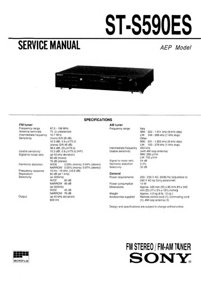
Other Sony Tuner manuals

Sony ST-D777ES User manual

Sony

Sony ST-D777ES User manual

Sony XT-100DAB User manual

Sony

Sony XT-100DAB User manual

Sony XDR-Fl HD User manual

Sony

Sony XDR-Fl HD User manual

Sony ST-JX4L User manual

Sony

Sony ST-JX4L User manual

Sony ST-88 User manual

Sony

Sony ST-88 User manual

Sony SVR-2000 User manual

Sony

Sony SVR-2000 User manual

Sony WRR-810A User manual

Sony

Sony WRR-810A User manual

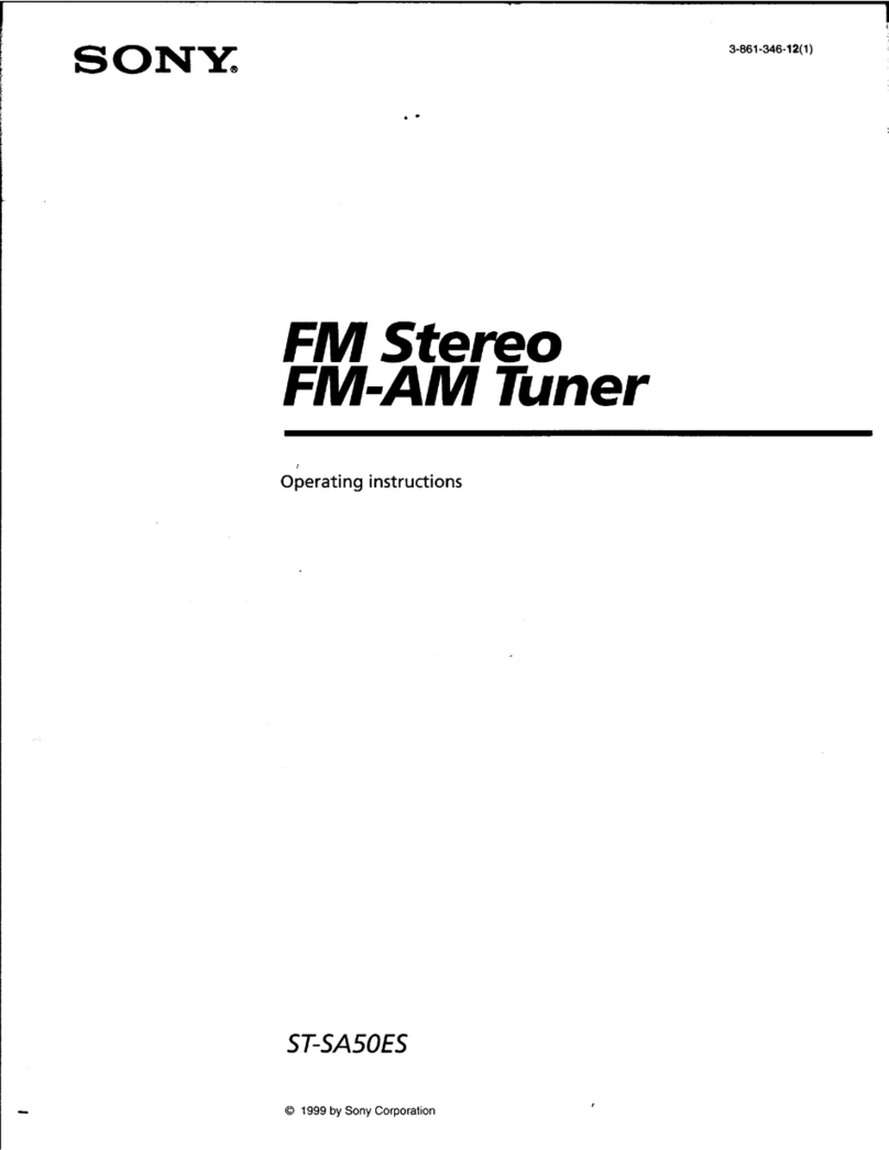
Sony ST-SA50ES - Am/fm Tuner User manual

Sony

Sony ST-SA50ES - Am/fm Tuner User manual

Sony ST-SA5ES User manual

Sony

Sony ST-SA5ES User manual

Sony XT-V70 User manual

Sony

Sony XT-V70 User manual

Sony ST-S590ES User manual

Sony

Sony ST-S590ES User manual

Sony hmd-m11 User manual

Sony

Sony hmd-m11 User manual

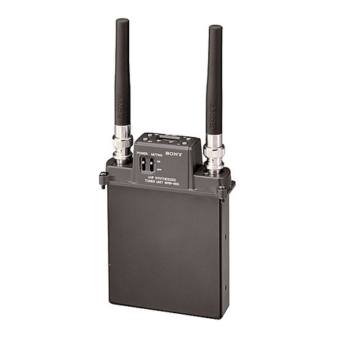
Sony WRR-855B User manual

Sony

Sony WRR-855B User manual

Sony WRR-801A User manual

Sony

Sony WRR-801A User manual

Sony HCD-WZ5 User manual

Sony

Sony HCD-WZ5 User manual

Sony WRR-800A User manual

Sony

Sony WRR-800A User manual

Sony XDRF1HD - HD Radio Tuner User manual

Sony

Sony XDRF1HD - HD Radio Tuner User manual

Sony HCD-D11 User manual

Sony

Sony HCD-D11 User manual

Sony MB-8N User manual

Sony

Sony MB-8N User manual

Sony WRR-801A User manual

Sony

Sony WRR-801A User manual

Sony WRR-800A User manual

Sony

Sony WRR-800A User manual

Sony ST-SV7 User manual

Sony

Sony ST-SV7 User manual

Sony ST-JX390 User manual

Sony

Sony ST-JX390 User manual

Sony ST-S770ES User manual

Sony

Sony ST-S770ES User manual

Popular Tuner manuals by other brands

Technics ST-HD55 Service manual

Technics

Technics ST-HD55 Service manual

Arcam DT91 Handbook

Arcam

Arcam DT91 Handbook

HDHomeRun 20121008 installation instructions

HDHomeRun

HDHomeRun 20121008 installation instructions

Eico HFT-92 instruction manual

Eico

Eico HFT-92 instruction manual

MFJ MFJ-928 instruction manual

MFJ

MFJ MFJ-928 instruction manual

Teac T-1D Service manual

Teac

Teac T-1D Service manual

NAD C 445 owner's manual

NAD

NAD C 445 owner's manual

Pioneer GEX-P700DAB Operation manual

Pioneer

Pioneer GEX-P700DAB Operation manual

Sirius Satellite Radio SC-FM1 user guide

Sirius Satellite Radio

Sirius Satellite Radio SC-FM1 user guide

Antique Automobile Radio 283501B Installation and operating instructions

Antique Automobile Radio

Antique Automobile Radio 283501B Installation and operating instructions

Sanyo FMT M15L Service manual

Sanyo

Sanyo FMT M15L Service manual

Monacor PA-1200R instruction manual

Monacor

Monacor PA-1200R instruction manual

Technics ST-X301L Service manual

Technics

Technics ST-X301L Service manual

Manhattan 176156 user manual

Manhattan

Manhattan 176156 user manual

Marantz ST-15S1 user guide

Marantz

Marantz ST-15S1 user guide

Korg HA-40 owner's manual

Korg

Korg HA-40 owner's manual

Pioneer XC-IS21T Service manual

Pioneer

Pioneer XC-IS21T Service manual

Harman Kardon TU915 Technical manual

Harman Kardon

Harman Kardon TU915 Technical manual

manuals.online logo
manuals.online logoBrands
  • About & Mission
  • Contact us
  • Privacy Policy
  • Terms and Conditions

Copyright 2025 Manuals.Online. All Rights Reserved.