South Galaxy G6 User manual

Galaxy G6
- 1 -
Galaxy G6 Measuring System
User Manual
*All Rights Reserved

Galaxy G6
- 2 -
Directory
Directory.................................................................................................................................... - 2 -
ChapterⅠBrief Introduction ................................................................................................... - 4 -
§1.1 Introduction ............................................................................................................... - 4 -
§1.2 Applications............................................................................................................... - 4 -
§1.3 Main Features ............................................................................................................ - 4 -
ChapterⅡHardware Component............................................................................................. - 7 -
§2.1 Mainframe ................................................................................................................. - 7 -
§2.1.1 Front Components .......................................................................................... - 7 -
§2.1.2 Side Components.......................................................................................... - 10 -
§2.1.2 Bottom Components..................................................................................... - 11 -
§2.2 Operation on receiver .............................................................................................. - 12 -
§2.2.1 Main configuration page............................................................................... - 12 -
§2.2.2 Mode Select.................................................................................................. - 12 -
§2.2.3 Datalink Setting............................................................................................ - 16 -
§2.2.4 System Setting.............................................................................................. - 20 -
§2.2.5 WIFI Config ................................................................................................. - 24 -
§2.2.6 Datalink Info (only for Base/Rover)............................................................. - 27 -
§2.2.7 Config Mode................................................................................................. - 28 -
§2.2.8 Power Off ..................................................................................................... - 28 -
ChapterⅢWeb UI Configuration .......................................................................................... - 29 -
§3.1 Overview ................................................................................................................. - 29 -
§3.2 Web UI main interface............................................................................................. - 30 -
§3.2.1 Status ............................................................................................................ - 32 -
§3.2.2 Configuration................................................................................................ - 33 -
§3.2.3 Satellite Information..................................................................................... - 39 -
§3.2.4 Data Record.................................................................................................. - 42 -
§3.2.5 Data Transfer ................................................................................................ - 43 -
§3.2.6 Network Config............................................................................................ - 48 -
§3.2.7 Radio Config ................................................................................................ - 54 -
§3.2.8 Firmware Update.......................................................................................... - 56 -
§3.2.9 User Management......................................................................................... - 58 -
§3.2.10 Help ............................................................................................................ - 59 -
ChapterⅣData Collector S10................................................................................................ - 60 -
§4.1 Basic introduction to the handheld .......................................................................... - 60 -
§4.2 Bluetooth Connection.............................................................................................. - 64 -
§4.3 Software installation and connecting....................................................................... - 65 -
ChapterⅤExternal Radio ...................................................................................................... - 68 -
§5.1 Overview ................................................................................................................. - 68 -

Galaxy G6
- 3 -
§5.2 Frequency Table ...................................................................................................... - 68 -
§5.3 Radio Appearance.................................................................................................... - 69 -
§5.4 Radio Interfaces....................................................................................................... - 70 -
§5.5 Transmitting Antenna .............................................................................................. - 70 -
§5.6 Application Notice................................................................................................... - 70 -
ChapterⅥAccessories ........................................................................................................... - 72 -
§6.1 Instrument Case....................................................................................................... - 72 -
§6.2 Batteries & Portable Power Package....................................................................... - 72 -
§6.2.1 Batteries........................................................................................................ - 72 -
§6.2.2 Portable power package................................................................................ - 74 -
§6.3 Differential Antennas............................................................................................... - 75 -
§6.4 Cables ...................................................................................................................... - 76 -
§6.5 Other Accessories.................................................................................................... - 77 -
Chapter ⅦMeasuring Operation .......................................................................................... - 79 -
§7.1 Static Operation....................................................................................................... - 79 -
§7.1.1 Static Measurements Profile......................................................................... - 79 -
§7.1.2 Operating Procedures ................................................................................... - 80 -
§7.1.3 Field Operation Notes................................................................................... - 80 -
§7.1.4 GPS Net Design............................................................................................ - 81 -
§7.1.5 Antenna Height Measurement ...................................................................... - 82 -
§7.2 RTK measurement................................................................................................... - 84 -
§7.2.1 By using radio (Internal radio) ..................................................................... - 84 -
§7.2.2 By using radio (external radio)..................................................................... - 95 -
§7.2.3 By using internet (GPRS)............................................................................. - 97 -
§7.2.4 By using internet (WIFI) ............................................................................ - 102 -
§7.2.5 Tilt Survey .................................................................................................. - 105 -
§7.2.6 Radio Router............................................................................................... - 108 -
Appendix A Galaxy G6 technical specifications ................................................................... - 109 -
Appendix B GDL-20 radio technical specifications.......................................................... - 111 -
Appendix C Technical Terms.............................................................................................. - 113 -

Galaxy G6
- 4 -
ChapterⅠBrief Introduction
Read this chapter, and you will have a brief knowledge of South Company and
Galaxy G6 measurement system.
§1.1 Introduction
Welcome to South Surveing&Mapping Instruments Co., Ltd, which is Chinas leading GPS
RTK instrument production and sales enterprises, has been committed to spread the international
advanced GPS mapping survey techniques and products to the users. To know more information
about SOUTH, please visit our official website http://www.southinstrument.com/
This manual takes Galaxy G6 measuring system for example, to explain how to install, set up
and uses the RTK system as well as the use of the accessories. We recommend that you read
these instructions carefully before using the instrument.
§1.2 Applications
Control Survey: dual-band (dual-frequency) system static measurements can accurately
complete the high-precision deformation observation, photo-control point measurement.
Highway Survey: quickly complete the encryption of the control points, road topographic
mapping, cross-section measurement, profile measurement with EGStar.
CORS Application: provide more stable and convenient data link for field operations. It is
seamlessly compatible with all types of domestic CORS applications.
Data acquisition measurement: perfect match Souths various measurement software to do
quick and easy data acquisition.
Stakeout shot:large-scale point, line, plane lofting.
Electric Power Measurement:power line measurement orientation, ranging, angle calculation.
Marine application:oceanographic research, dredging, piling, inserted row, making the marine
operations more convenient and easy.
§1.3 Main Features
Intelligent Platform
Combine embedded Linux operating system with SOUTH smart cloud, Galaxy G6 will no

Galaxy G6
- 5 -
longer be a separate hardware device, but a complete intelligent system, with the aid of the
SOUTH powerful cloud service platform, users are able to register the receiver, upgrade
firmware and diagnosis in real-time by remote control service. Never leave home you can enjoy
the star service from SOUTH.
Bluetooth
Galaxy G6 is equipped with Bluetooth 4.0 module, which is pioneer to adopt this technology to
support communication with smartphone, tablet PC etc, to make sure Bluetooth communication
more stable
WiFi
As the new feature and technology adopted on Galaxy G6, G6 allows users to control and
configure the receiver by connecting its broadcasted wifi hotspot with any kind of mobile
terminal. Also Galaxy G6 is the first to adopt WiFi as datalink that greatly improve the flexibility
of actual measurement.
Advanced InBuilt UHF module
Galaxy G6 adopts new and excellent datalink system, which is compatible with current radio
protocols in the market, also supports all kinds of network types to access CORS seamlessly
Speed Dial
Based on Linux platform and PPP dial-up technology, which ensures the stability of network
connection for Galaxy G6 in the process of measuring.
Intelligent Interaction
Support to access the internal web UI manage page of receiver with WiFi and USB connection,
monitor host state real-time, configure receiver freely.
Attractive OLED Display
Galaxy G6 is installed with a more attractive OLED display that mode settings and status are
intuitive and easy to know from the screen
Smart Voice Guide
The customizable iVoice technology is allowed to customize your local language. Multi-lingual
and clear-tone messages enable users to understand the critical information and status of receiver
such as network connection, solution status, working mode and more, which definitely helps to
improve work efficiency by being acknowledged.
Full Constellations Tracking
Equipped with most advanced GNSS boards, Galaxy G1 system can track most signal from all

Galaxy G6
- 6 -
kinds of running satellite constellation, especially support B1,B2 and B3 signal from COMPASS,
also get position result with only COMPASS signal
Electronic Bubble & Tilt Compensation
The internal tilt compensator and electronic bubble can correct the coordinate result
automatically at the points with tile angel and tile direction
Large capacity power support
Galaxy G6 is equipped with 2 large capacity (7.4V, 6800mAh), removable and rechargeable
Li-ion batteries, they are checked the remaining power real-time.
The portable power source package can last up to 24 hours continuous work, which provides
almost 2-3 working days. Plus the pioneered power saving mode, the battery package ensures G6
can complete the measurement under static mode and base mode.
Intelligent Storage
Galaxy G6 supports variety of raw data storage including STH, Rinex2.01 and Rinex3.02. The
internal 8G SSD (Solid State Drive) ensures long time data collection. And as an OTG host, G6
also allows to extend an external USB device for the storage.
The configurable sample frequency is really up to 50Hz.
The one-key intelligent copy function enables users download static data from receiver by
inserting an USB storage to receiver directly without bringing the unit back to office, that
extremely improves the efficiency and the demanding of static fieldwork.
Amazing Housing
Galaxy G6, with and innovative design, built with magnesium alloy materials. And the top edge
is design to decrease harm for receiver in case of fall down to ground
NFC Function
The internal NFC module can make the complicated Bluetooth communication more easy and
simple
Cloud Service
The function enable realize online upgrade and register, remote diagnosis in real-time

Galaxy G6
- 7 -
ChapterⅡHardware Component
Reading this chapter, you can grasp the components, installation and the function of
Galaxy G1 measuring system
§2.1 Mainframe
The mainframe is a flat cylindrical, 137mm in height, 152mm in diameter, the height from the
rubber seal ring to the bottom is 60mm. the body is made up of magnesium alloy material, it
makes overall the G6 be more rugged and durable. Galaxy G6 adopts LCD and buttons
combination design, install with an attractive OLED display that mode settings and status are
intuitive to know, easy to operate. At the side and the bottom of receiver there are the frequency
used interfaces.
§2.1.1 Front Components
Ref
Component
Description
①
UHF antenna interface
Install UHF receiving/transmitting antenna
②
Indicators
Indicates the working status for receiver
①
③
②
④
⑤

Galaxy G6
- 8 -
③
F Key
Page up/down, selection button
④
Power Key
Power on/off receiver, confirm button
⑤
OLED Display
Display the working mode and status of receiver
Indicators
The indicators are located at the left side of front component, details meaning please check the
table below.
Ref
Component
Description
①
Glows in red to indicate that Bluetooth connection has established
②
Flashes in red to indicate that the static data is storing with the
sample interval
③
UHF mode: Flashes in red to indicate that the signal is
receiving/transmitting with the interval
GPRS mode: 1) Fast flashes in red to indicate that the receiver is
dialing; 2) Flashes in red with the signal receiving/transmitting
interval when successful dial
WiFi mode: 1) Fast flashes in red to indicate that the receiver is
establishing WiFi connection; 2) Flashes in red with the signal
receiving/transmitting interval when successful connection
④
Glows in red if there is enough power in battery
Flashes in red to inform you the battery is going to run out and 5
minutes left when it starts blinking

Galaxy G6
- 9 -
Display and main interface
Power on G6 and after initializing, it will get into the main interface and begin to search the
satellite like a radar on skyplot, then you will get a voice saying the working mode, 10 seconds
later the screen will automatically switch to display the coordinates and other information.
The satellite information will display on this interface such skyplot, the number of satellite and
PDOP status
Coordinates page
Skyplot page
Ref
Component
Description
①
Battery symbol
Display the electricity quantity in real-time
②
Coordinates
Display the coordinates of base or rover
③
Solution/Message type
It will display the message type transmitted when the
receiver is set as base; and it will display the solution type
when the receiver works as rover
④
Message symbol
The message symbol will appear automatically if receiver
gets something error, such as error message. Press F key
to read the message and press F key again to cancel
⑤
Temperature
Display the temperature of receiver in real-time
⑥
WiFi symbol
Display the WiFi status, when it shows , that
①
③
⑤
②
⑥
⑧
⑦
④
Galaxy G6
- 10 -
means the receiver is establishing WiFi connection as
WIFI client, and if the WIFI successfully connected the
symbol will change to be ; when it shows ,
that means the receiver is broadcasting its WIFI hotspot
(We recommend to turn it off while unused.)
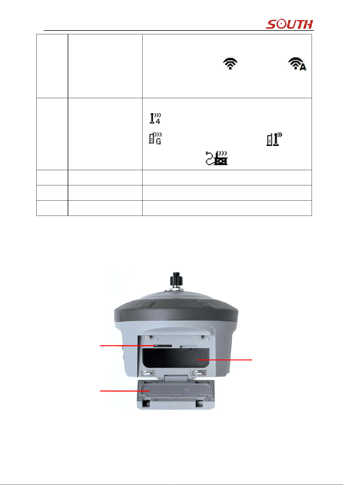
⑦
Data link symbol
G6 will indicate the current used datalink at this location.
means internal UHF mode and the current channel,
means the GPRS mode, means
dual-emitting mode, means externl device mode
⑧
Skyplot
Display the satellites distribution
Satellites
The value under Sats indicates the number of satellites
PDOP
Display current PDOP value
§2.1.2 Side Components
①
②
③

Galaxy G6
- 11 -
Ref
Component
Description
①
SIM card slot
Where we can insert a SIM card when the receiver is set in
GPRS mode
②
Battery cover
Restore the cover after installing the battery to avoid the
battery slips off
③
Battery housing
Installing the battery
§2.1.2 Bottom Components
Ref
Component
Description
①
Screw hole
Fix the mainframe to the tribrach or the pole
②
SN label
Apply for a registration code, Bluetooth ID
③
Speaker
Mode setting and working status prompt
④
GPRS antenna interface
Install GPRS antenna
⑤
5-pin port
As a power port connected with an external power
supply device; as a differential transmission port
connected with an external radio; as a serial port to
check data output and debug
⑥
7-pin port
USB port, OTG interface and Ethernet port
③
②
①
④
⑤
⑥

Galaxy G6
- 12 -
§2.2 Operation on receiver
§2.2.1 Main configuration page
Press once on F key after power on receiver to get into the configuration interface, then you will
have Mode Select, Set Datalink, System Option, WIF Config, UHF Info, Config Mode, Power
Off and Quit.
Press F key to move the box to the option which you need to configure, and then press Power
key to confirm your selection.
§2.2.2 Mode Select
Power on receiver and press F key to get into main configuration interface, move the select box
to Mode Select option, press Power key to confirm and enter Mode Select page, there you will
have Static Mode, Base Mode and Rover mode.
Static Mode Setting
To make a static job with Galaxy G6, first you have to set the receiver in Static mode.
Get into the Mode Select page and place the select box at the Static Mode (first item), then press
Power key to confirm and return to Coordinate/Skyplot page

Galaxy G6
- 13 -
What we should do in the next is setup all the parameters for static mode. Press power key once
and enter Record Option page, all the parameter items are displayed here including point name,
antenna height, sample interval, record mode and data type.
Site: this is point ID for static, and it is the last 4 digits from serial number, but you can edit it if
you choose this item, there are 0-9 and A-Z for each digit.
Ant.Hgt: This is the antenna height measure from ground point to measurement tape
Interval: This is the sample rate for raw data storage
Rec.Mode: This is used to configure receiver to store raw data automatically or manually if
achieve sampling condition
DataType: This is used to choose the data format for raw data storage, such as STH, Rinex2.01
and Rinex3.02
Press F key to move to Edit option and press power key to confirm, here you can select the item
to edit by pressing F key. For example, press F key to move to Datatype item and press power
key to setup what kind of data format we are going to record, press F key to move to Rinex2.x or
Rinex3.x and press power key to confirm, after that, press F key to move to OK option and press
Power key to finish setting and return to the coordinate/skyplot page.
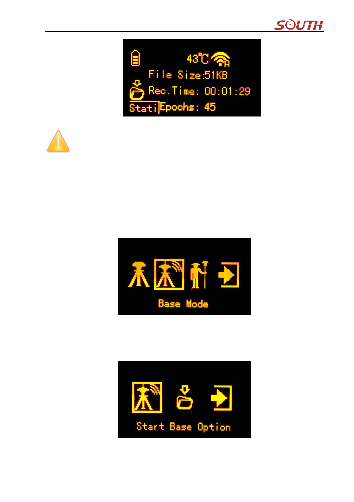
The receiver will start to record the data if achieve the sampling conditions, at this moment,
recording information will be shown on the screen such as file size, recording time and the
epochs.
File Size: Real-time display the size of data file
Rec.Time: Real-time display the recording time
Epochs: Real-time display the quantity of epochs receiver already obtained
Galaxy G6
- 14 -
NOTE: Please ensure the parameter values static mode are the same if there are more
than 2 pcs units work at the same time.
Base Mode Setting
Press F key after initialization to get into configuration interface, then move select box to Mode
Select option and press Power key to enter Mode Select page, move the select box to Base Mode
(second item) and press Power key to confirm. Once return to coordinate/skyplot page, press
power key to enter Base configuration page. Start Base Option, Record Option and Quit option
are displayed in this page.
Start Base Option
This option is to control and setup the parameters for the transmission when base station
achieves the transmitting conditions.
Base Mode: Manual, Repeat and AutoBase for optional to start the base station.

Galaxy G6
- 15 -
Diff Type: This is the correction format which base support to transmit, there are RTD,
RTCM23, RTCM30, RTCM32,CMR, SCMRX for optional.
Mask Angle: It is a altitude restricted angle which is an angle defined from horizontal level to
the sky direction, it is mainly used to control satellite view for GPS receiver. 10-15 degree is the
default setting.
Record Option
That is used to control and setup the parameters for base station to record raw data or not
Rover Mode Setting
Press F key after initialization to get into configuration interface, then move select box to Mode
Select option and press Power key to enter Mode Select page, move the select box to Rover
Mode (third item) and press Power key to confirm. Once return to coordinate/skyplot page, press
power key to enter Rover configuration page. Rover Setting, Record Option and Quit option are
displayed in this page.

Galaxy G6
- 16 -
Rover Setting
This is used to configure the mask angle and SBAS satellite view for rover receiver
Mask Angle: It is a altitude restricted angle which is an angle defined from horizontal level to
the sky direction, it is mainly used to control satellite view for GPS receiver. 10-15 degree is the
default setting.
SBAS SV: This is used to control the rover receiver to track the SBAS system or not.
Record Option
That is used to control and setup the parameters for rover station to record raw data or not, it is
similar to the base station.
§2.2.3 Datalink Setting
Galaxy G6 is integrated with a series of excellent and advanced datalink modules make it be an
extremely powerful system that includes built-in radio module, cellular module, Bluetooth and
WIFI, G6 is not only able to connect with the external module, but also can close the datalink if
it is not the necessary use.

Galaxy G6
- 17 -
Press F key to get into main configuration interface after the initialization or the working mode
has been setup, then move the select box to Set Data Link option by pressing F key, and press
power key to confirm and enter the interface, there are UHF, Cellular Net, Bluetooth, Dual
Transmitting, WIFI Datalink, External, Close Datalink and Main menu options displayed on this
interface.
UHF Setting
Select UHF option and then get into its configuration interface, then you can setup the channel,
air baud rate, communication protocol and power for internal UHF.
Channel: This is the communication channels for internal UHF, the value of the channel must
be the same both in Base and Rover.
Air Baud: This represents the radio transmission rate of data, the higher value, the bigger of
data size transmitted per second, in this page, there are 9600 and 19200 for selection. The default
setting is recommended to use, Base and Rover must have the same rate if it is changed.

Galaxy G6
- 18 -
Protocol: This is radio communication protocol for data transmission, SOUTH and TRIMTALK
are optional in this page and SOUTH is the default setting, if it is changed, Base and Rover must
use the same protocol for communication.
Power: This appears only in Base mode, the radio transmitting power is allowed to define in
High, Middle or Low power.
Cellular Net Setting
This mode is using the internal cellular module that connect to internet and access to reference
station for the corrections.
Dual Transmitting Mode
This mode is used for the Base station that it is able to transmit the corrections by both internal
UHF and cellular net.

Galaxy G6
- 19 -
Bluetooth Mode Setting
This mode is used on Rover that access the reference station for corrections by using data
collector internet that transfer the corrections to receiver through Bluetooth.
WIFI Datalink Setting
This is the pioneer to use WIFI as the datalink that connect to the internet and access to reference
station for corrections. (detail settings please refer to .)
External Device
Setup this mode to connect the external datalink such as external radio module or external GPRS
module.

Galaxy G6
- 20 -
Close Datalink
This option is used to turn off all of the transmission method for development and customization,
usually keep all the datalink activated.
§2.2.4 System Setting
In System Setting, you will have more configurations for Galaxy G6 that includes Language
setting, Voice option, selfcheck, online service and so on.
Move the select box to System Option and then enter the configuration page, there you will have
Language, Voice Option, System Info, Self Check, Online Option, Other Option and Copy Static
File items displayed on this page.
Language
The Language page contains Chinese, English, Russian, Korean, Spanish and Portuguese, users
can setup to show their local language on G6.
Table of contents
Other South Measuring Instrument manuals

South
South ET-02 User manual

South
South N3 Series User manual

South
South N9 Series User manual

South
South Galaxy G2 User manual

South
South A1 Series User manual

South
South NTS-960R User manual

South
South N40 Series User manual

South
South Galaxy G1 User manual

South
South GALAXY G7 User manual

South
South N6 Series User manual


