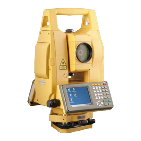
South N6+ Series User manual

Operation Manual
N6+ Series
Mechanical Total Station

© South Surveying & Mapping Technology CO.,LTD All Rights Reserved

INDEX
1.SPECIFICATION........................................................................1
1.1 EDM..........................................................................................1
1.2 Others......................................................................................2
2.BRIEF INTRODUCTIONS……………………...........................................4
2.1 Appearance…………….....................................................................4
2.2 Keyboard…………….....................................................................5
2.3 Star Key……………..…….....................................................................6
2.4 Hot Keys……….………….....................................................................8
2.5 System Inforamtion……….……….....................................................8
3.PREPARATION………………………………...........................................9
3.1 Preparation…...……………………………...........................................9
3.2 Instrument Setup…...……………………………..................................9
3.3 Battery………..……...……………………………................................11
3.4 Tribrach……..……...……………………………................................12
3.5 Eyepiece Focusing...……………………………................................13
3.6 Parameters……….....……………………………................................13
3.6.1 Unit Set............................................................................13
3.6.1.1 Feet...........................................................................13
3.6.1.2 Angle.........................................................................13
3.6.1.3 Distance....................................................................14
3.6.1.4 Temp & Press............................................................14
3.6.2 Mode Set.........................................................................14
3.6.2.1 Power On Mode........................................................14
3.6.2.2 Dist Mode........................................................................15
3.6.2.3 NEZ/ENZ....................................................................15
3.6.2.4 V Angle Z0/H0...........................................................15
3.6.3 Other Set.........................................................................15

3.6.3.1 Min Angle Read........................................................15
3.6.3.2 Min Dist Read...........................................................15
3.6.3.3 Face in L or R.............................................................16
3.6.3.4 Auto Power Off.........................................................16
3.6.3.5 H-Angle Buzzer..........................................................16
3.6.3.6 Meas Buzzer..............................................................17
3.6.3.7 W-Correction............................................................17
3.6.3.8 Data & Time..............................................................17
3.6.3.9 Grid Factor..............................................................17
3.6.3.10 IMP/EXP Order..............................................................18
3.6.4 Initial Set…………………............................................................18
4.ANGLE MEASUREMENT...............................................................19
4.1 [F1] ALL...............................................................................................19
4.2 [F2] 0 SET.............................................................................................21
4.3 [F3] H SET....................................................... ............. .......................21
4.4 [F1] HOLD...........................................................................................22
4.5 [F2] REP............................................................ ............. ....................22
4.6 [F3] V%...............................................................................................24
4.7 [F1] CPMS..........................................................................................24
4.8 [F2] R/L...............................................................................................24
4.9 [F3] FILE..............................................................................................25
5.DISTANCE MEASUREMENT.............................................................26
5.1 [F1] ALL...............................................................................................26
5.2 [F2] MEAS...........................................................................................26
5.3 [F3] MODE.........................................................................................26
5.4 [F1] HT................................................................................................27
5.5 [F2] BS.................................................................................................27
5.6 [F3] OCC............................................................................................28

5.7 [F1] OFSET..........................................................................................29
5.7.1 Angle offset..............................................................................29
5.7.2 Distance offset.................................. ......................................30
5.7.3 Plane offset...............................................................................30
5.7.4 Column offset...........................................................................31
5.8 [F2] S.O...............................................................................................32
5.9 [F3] FILE..............................................................................................33
6.COORDINATE MEASUREMENT......................................................34
7.MENU...................................................................................................35
7.1 Data Collect.....................................................................................36
7.1.1 New Job.....................................................................................36
7.1.2 OCC PT Input............................................................................37
7.1.3 Backsight................................................................................38
7.1.4 FS/SS................................................................................39
7.1.5 Resection.........................................................................39
7.1.6 Config of Data Collect......................................................41
7.1.6.1 Collect Sequence......................................................41
7.1.6.2 Data Confirm............................................................41
7.1.6.3 Select SD/HD.............................................................41
7.2 Stake Out.....................................................................................42
7.2.1 Layout Pt....................................................................................42
7.2.2 Side Shot.....................................................................................43
7.3 Memory Management...........................................................44
7.3.1 File Maintain...................................................................44
7.3.1.1 Meas. File.................................................................44
7.3.1.2 Coord File..................................................................44
7.3.1.3 PCode File.................................................................45
7.3.1.4 Known Coord..................................................................46

7.3.2 Data Transfer...................................................................48
7.3.2.1 Connection between N6+ and PC...............................49
7.3.2.2 Send Data.................................................................49
7.3.2.3 Load Data.................................................................50
7.3.3 Edit the Known Coordinates.............................................51
7.3.4 Select the Code File.........................................................51
7.3.5 Disk Attribute..................................................................51
8.PROGRAMS..........................................................................52
8.1 REM........................................................................................52
8.2 MLM.......................................................................................53
8.2.1 MLM-1 (A-B, A-C)............................................................54
8.2.2 MLM-2 (A-B, B-C)............................................................56
8.3 Z Coordinate...........................................................................57
8.4 Area........................................................................................59
8.5 Point to Line...........................................................................60
9.ROADS..................................................................................62
9.1 Case Study - H & V Curve in Ramp.........................................62
9.1.1 Design Drawing of H & V Curve.......................................62
9.1.2 How to Use N6 to Calculate the H&V Curve in Ramp......63
9.1.2.1 Create a new file as the current job.........................63
9.1.2.2 Input the designed value of horizontal curve...........64
9.1.2.3 Input the designed value of vertical curve...............66
9.1.2.4 Calculate the coordinate of main pile......................67
9.1.2.5 Export the data.........................................................68
9.1.2.6 Use AutoCAD to open the dxf file.............................69
9.1.2.7 Layout points............................................................70
9.1.2.8 Inverse calculation....................................................72
9.1.2.9 Layout the middle and side piles..............................75

9.2 Case Study - H Curve in Renovation Project...........................76
9.2.1 Design Drawing for the H Curve JD17.............................76
9.2.2 Transfer the Form into Linear Elements..........................76
9.2.3 How to Use N6 to Calculate the Road in H Curve............78
9.3 Case Study - V Curve in Road Project.....................................82
9.3.1 Design Drawing for the V Curve JD39-JD43.....................82
9.3.2 Transfer the Form into Linear Elements..........................83
9.3.3 How to Use N6 to Calculate the Road.............................83
9.4 Case Study - H Curve A13 in High-Speed Road.......................91
9.4.1 Design Drawing for A13............................................. ......91
9.4.2 Transfer the Form into Linear Elements..........................91
9.3.3 How to Use N6+ to Calculate the Road.............................92
9.5 Case Study - Road in Residence Community..........................99
9.6 Case Study - Road in Tunnel...................................................104
10.ADJUSTMENT & INFORMATION.......................................................108
10.1 Adjustment.............................................................................108
10.1.1 V0 Adjustment (i angle)..................................................108
10.1.2 Collimation (2C) ..............................................................109
10.1.3 Horizontal Axis................................................................. 109
10.1.4 V0/Axis Const..................................................................110
10.1.5 Sensor Adj...................................................................110
10.2 Instrument Constant & Information.......................................110
10.2.1 Inst. Constant..................................................................110
10.2.2 Information.....................................................................111

1
1. SPECIFICATIONS
1.1 EDM
Carrier Wave
0.65~0.69μm
Effective Range of Bluetooth
10m
Reflectorless Range
1000m/1500m optional
Oscillation Frequency
150MHz
EDM Type
Coaxial
Minimum Reading for Distance
0.1mm
Laser Dot without Reflector
(Red laser beam)
Around 7mm×14mm/20m
Around 10mm×20mm/50m
Atmosphere Correction
Manual Input, Auto correction
Earth Curvature Correction
Manual Input, Auto correction
Prism Constant
Manual Input, Auto correction
Dist.Unit
Meter/US.Feet/International
Feet/ Feet-inch optional
Average Measure Time
3 Times
Distance Measurement
Accuracy With Reflector
Measure Mode
Accuracy
Time
Fine Mode
±(2+2×
6
10−
·D*¹)mm
<0.3s
Tracking Mode
±(5+2×
6
10−
·D)mm
<0.1s
IR Sheet Mode
±(2+2×
6
10−
·D)mm
<0.3s
Accuracy w/o Reflector
*with Kodak Gray Card White Side (90% reflective)
Fine Mode <500m
±(3+2×
6
10−
·D)mm
0.3~3s in normal,
less than 10s
Fine Mode >500m
±(5+2×
6
10−
·D)mm

2
Tracking Mode
±(10+2×
6
10−
·D)mm
Max. Range
With Reflector
*²Good Conditions
Single Prism
5000m
IR Sheet
1000m
Without Reflector
*²Good Conditions
White*³
1000m
Gray Degree 0.18
450m
*¹D= distance in mm
*²Good Conditions: slight haze, visibility about 20km
*³Kodak Gray Standard (90% reflective)
1.2 Others
Angle Measurement
Measuring Method
Absolute Encoding
Diameter of Encoding Disk
79mm
Minimum Reading for Angle
0.1″/1″/5″/10″optional
Accuracy
2.0″/5.0″
Telescope
Image
Erect
Tube Length
154mm
Effective Aperture
45mm (EDM:50MM)
Magnification
30x
Field of View
1°30’
Minimum Focus Distance
1.2m
Resolving Power
3”
Compensator
System
Dual axis liquid-electric
Working Range
±4’
Accuracy
1”

3
Vial
Plate Vial
30”/2mm
Circular Vial
8’/2mm
Laser Plummet
Accuracy
±1.5mm( at 1.5m)
Optical Plummet (OPTIONAL)
Image
Erect
Magnification
3 x
Focusing Range
0,5m~∞
Field of View
5°
Display Unit
Type
6 Lines LCD screen
Data Communication
Port
USB Stick up to 256G, Bluetooth
Battery
Type
Rechargeable Lithium battery
Voltage
7.4V DC, 3100mAH
Continuous Operation Time
10 hrs
Working Environment
Temperature
-20℃~+50℃
Dimension
Size
190mm×195mm×335mm
Weight
5.5kg
* The manufacturer reserves the right to make technical changes
without prior notice *

4
2. BRIEF INTRODUCTION
2.1 Appearance
1
Handle
2
Battery Lock
3
Battery
4
Optical Unit
5
Optical Focusing Ring
6
Eyepiece Handle
7
Eyepiece Focusing
Ring
8
Eyepiece
9
Collimator
10
Central Mark
11
Vertical Clamp and
Tangent Unit
12
Vial Bubble
13
Horizontal Clamp
and Tangent Unit
14
Trigger Key
15
Display Unit
16
Power Key
17
USB Comm Port
18
Circle Bubble
19
Tribrach Lock
20
Leveling Screw
21
Base
1
2
3
4
9
15
10
16
19
14
13
20
17
22
21
12
11
8
5
6
7

5
2.2 Keyboard
The icon shown as below:
Key
Name
Function
Star key
Enter the star mode
Angle
measuring
Enter the angle measurement mode
Distance
measuring
Enter the distance measurement mode
Coordinate
measuring
Enter coordinate measurement mode
Menu
Enter menu
Esc
Cancel operation, or return to the last page
Power key
Power ON/OFF
~
Function key
Functions correspond to information displayed
~
Number keys
numbers/characters, or select items/hot keys
Move keys
Move the cursor to the left, right, up and down
Enter
Confirm the data, or go down to next item
Icon
Meaning
Operation
Dual sensor
Single sensor
Horizontal Left
Function Key
Function Key
Enter
Esc
Star Key
Menu/Move Right
Num./Alph.Key
Power Key
Cord./Move Left
Angle/Move Up
Distance/Move Down
ALL OSET HSET
Vertical Angle

6
2.3 Star Key
Press [★] to activate the Star Key menu, press direction key [▲] [▼]
[▶] [◀]to move the cursor, press function keys to operate. Press [ESC]
to exit the menu.
(1) Direction keys
Reflector: the default setting is NON-P. Press [▶]to switch among
Prism, Sheet and Non-prism mode.
Plummet: the intensity for laser plummet. Press [◀]to switch the
value among 2→1→0→4→3→2, 0 means off.
Contrast: the default value is 10. Press [▲]to switch the contrast
for LCD screen among 10→11→……→16→00→01→02……→09→10.
CrosHair: Illumination for crosshair (reticle unit). The default value
is 0. Press [▼] to switch the value among 0→1→2→3→4→0, 0
means off.
(2) Function keys
ILL: Illumination for LCD screen and keyboard. The default
Sensor closed
Bluetooth
Bluetooth on.
Reflectorless
mode
Reflector mode
Reflector sheet
Battery voltage
Display the battery voltage in real time

7
setting is on. Press [F1]to open or close the illumination.
TILT: On/Off the tilt sensor. The default setting is dual-axis
sensor. Press [F2]to enter 1/2 page. Then press [F1] X-ON for single
X-axis compensation, press [F2]XYON for dual-axis compensation.
Press [F3]OFF to close the compensator. Press [F4]to enter 2/2
page. It will display the compensate value on current position.
Point: On/off laser pointer. The default setting is off. Press [F3]
to switch the laser pointer between on and off.
PARA: Parameter setting menu.
Input the value of temperature and atmosphere pressure. It will
calculate the PPM automatically based on the atmosphere
correction.
Reference value: Temperature 20℃, pressure P=1013hPa
Calculation formula:
t
P
003661.01 294922.0
44.278PPM +
−=
Users can also calculate the PPM value based on the formula by
themselves and input the value by manual.
Note: a) Input range for temperature :-30℃~+60℃, increased by
0.1 ℃; Input range for atmosphere pressure560~1066hPa,
min.0.1hPa increase. B) Input range for PPM is -999.9~999.9ppm.

8
2.4 Hot Keys
When the total station is under the basic measurement surface, click
the numeric keyboard to quickly access to the other pages.
2.5 System Information
Hold the power key in 1s to power on. The initial page is the angle
measurement mode (pic a), press [ESC] to enter the system
information page (pic b).
Press [Menu] - [F4] P2 - [3] Information to check the hardware
information (pic b).
Key
Quick Access To
0
Stake Out
.
Tilt Sensor
-
Data Confirm
1
Memory MGR.
2
View Meas File
3
View Coord File
4
Resection
5
Created Meas & Coord File
6
Read Coordinate File
7
STN Setup
8
BS setup by coordinate
9
BS setup by angle

9
3. PREPARATION
3.1 Preparation
Unpacking
Lay down the case lightly with the cover upward. Unlock the case
and take out the instrument.
Storage of Instrument
Cover the cap, put the instrument into the case with the vertical
clamp screw tightened and circular vial upwards (lens towards
tribrach).
3.2 Instrument Setup
1) Setting up the tripod
A. Loosen the screws on the tripod legs, pull out to the required
length and tighten the screws.
B. Make the center of tripod and the occupied point approximately
on the same plumb line.
C. Step on the tripod to make sure if it is well stationed on the ground.
2) Instrument setup (Laser plummet)
A. Place and fix the instrument carefully on the tripod
B. Press [★]and turn on the laser plummet. Hold the two legs which
are not fixed on the ground and decide the position to fix according
to the laser dot. When the laser dot is roughly on the station point, fix
those 2 legs.
Instrument setup (Optical plummet)
Adjust the eyepiece of the optical plummet telescope to your
eyesight. Slide the instrument by loosening the tripod screw; place

10
the point on the center mark of the optical plummet. Sliding the
instrument carefully as to not rotate the axis will allow you to get the
least dislocation of the bubble.
3) Roughly leveling by the circular vial
A. Rotate the foot-screw A and B to
move the bubble in the circular vial,
in which case the bubble is located
on a line perpendicular to a line
running through the centers of the
two leveling screw being adjusted.
B. Rotate the foot-screw C to move the bubble to the center of the
circular vial.
4) Leveling by the plate vial
A. Rotate the instrument horizontally
by loosening the horizontal clamp
unit and place the plate vial
parallel to the line connecting
rotating the foot-screw A and B,
and then bring the bubble to the
center of the plate vial by rotating
the foot-screw A and B.
B. Rotate the instrument in 90º
(100gon) around its vertical axis and
turn the remaining leveling screw or
leveling C to center the bubble
once more.

11
C. Repeat the steps and check whether the bubble is correctly
centered in all directions.
If the laser or optical plummet doesn’t stay at the center position
after levelling, please slightly loosen the screw under the tripod head
and move the instrument (don’t rotate the instrument) until the
equipment is on the station point. Tighten the screw and level the
instrument again. Repeat these steps until the instrument is precisely
centered and leveled.
Note: You can also level the instrument precisely by the E-bubble.
When the tilt is over ±4’, the system will enter the adjusting page of tilt
sensor automatically.
3.3 Battery
Inserting
Put the battery into the instrument. Check and insert it correctly to
side into the housing.
Replacing
Press the battery lock on the top of batter case, then remove the
battery. When the remaining voltage is less than one grid, please
stop your operation and charge it as soon as possible.
Before remove the battery from the instrument, make sure that the
power is turned off. Otherwise, the instrument may be damaged.
Charging
The battery must be charged prior to using before the first time

12
operation.
The battery LB-01 should be charged only by the official charger NC-
10, which packed together with the instrument. Please connect the
power supply in 110V - 220V, among 0°~±45°C.
When the indicator on the charger is red, the charging process has
begun. When indicator turns green, the charging has finished. For
safety, please pull out the battery and charger in time.
In order to get the maximum service life, please charge the battery
at least once in a month.
Note:
a) The operating time depends on the outside conditions, such as
ambient temperature, charging time, the cycles of charging,
etc. It is recommended for safety to charge the battery
beforehand or to prepare spare full-charged batteries.
b) The remaining voltage of battery shows the power regarding to
the current measure mode. The consumption of distance
measurement is higher than angle measurement in normal.
When switching the measurement mode from angle to distance
in a low battery voltage, the equipment might be interrupted.
3.4 Tribrach
Dismounting
If necessary, the instrument can be
dismounted from tribrach. Turn the
locking knob in 180° counter-clockwise
to disengage anchor jaws, and take off
the instrument.

13
Mounting
Insert three anchor jaws into holes of tribrach and line up the directing
stub. Turn the locking knob about 180° clockwise to mounting the
instrument.
3.5 Eyepiece Focusing
Sight the Telescope to bright place and rotate the eyepiece tube to
make the reticle clear. Roughly collimate the target by the top of
the triangle mark on EDM cover.
Rotate the focusing screw on eyepiece to make the image clear.
3.6 Parameters
Press [Menu]-5.Parameters to
set the total station.
3.6.1 Unit Set
3.6.1.1 Feet
Select the unit of N6+ total station between international feet and
USA fee. 1 international feet = 0.999 845 6 USA feet.
3.6.1.2 Angle
Select the angle unit among DEG(degree), GON and MIL. The
default select is DEG. 360 DEG = 400 GON = 6400MIL.
4.INITIAL SET
Table of contents
Other South Measuring Instrument manuals

South
South Galaxy G1 User manual
South
South ET-02 User manual
South
South N3 Series User manual
South
South GALAXY G7 User manual

South
South N40 Series User manual

South
South N9 Series User manual
South
South N6 Series User manual
South
South NTS-960R User manual

South
South Galaxy G6 User manual

South
South Galaxy G2 User manual


