South A1 Series User manual


1
PRECAUTIONS
Congratulations on your purchase of a new A1 total station!
Please read carefully through the User Manual before you switch on the product.
1. Do not collimate the objective lens directly to the
sunlight without a filter.
2. Do not stare at the laser beam, or point the laser to
the others’ eye!
3. Do not store the equipment in extremely high or low
temperature.
4. When the equipment is not in use, store it in the case
to avoid dust and humidity.
5. If there is a great difference between the
temperature in work field or store place, you should
leave the equipment in the case until it adapts to the
temperature of environment.
6. If the equipment has not been used for a long time,
you should remove the battery for separate storage.
The battery should be charged once a month.
7. When shipping the equipment, please place it in the
carry case. The cushioned material should be used to
cover around the case for support.
8. Clean the exposed optical parts by absorbent
cotton or lens-paper only!
9. Clean the surface softly with a woolen cloth. If it gets
wet, you should dry it immediately before switch-on.
10. Please check the power-supply, functions,
indications and parameters of the equipment goes
well before operation.
11. Do not disassemble the total station by yourself.
Please contact your authorized agency or South
Group when you find the equipment abnormal.

2
CONTENTS
1. INTRODUCTION……………………………...1
1.1 Features…………………………………...1
1.2 Appearance……………...……………...2
1.3 Measuring Preparation…………....…...3
1.4 Setting Up…………...…………………....3
1.5 Battery Information…………...………...5
1.6 Dismounting/Mounting the Tribrach…7
1.7 Eyepiece Focusing…………...………...7
2. OPERATION…………………………….........8
2.1 Symbols…………...……………………....8
2.2 Function Keys…………...………..……...9
3. MEASUREMENT………………...…………..10
3.1 Angle Measurement…………...……..10
3.2 Distance Measurement……………....11
3.3 Coordinate Measurement…………...12
4. STATION…………………...………………...13
4.1 Known Point…………...………………..13
4.2 Station Height…………...……………...14
4.3 Backsight Checking…………...………14
4.4 Resection…………...…………………...15
4.5 Point to Line…………...………………...16
5. COLLECT………………...……………….....17
5.1 Measure Points…………...………….....17
5.2 Distance Offset…………...………...….18
5.3 Plane Offset…………...……………......19
5.4 Column Offset…………...……………..20
5.5 MLM…………...………………………....21
5.6 Line & Extend Point…………...……..…22
5.7 Line & Extend Angle…………...………23
5.8 REM…………...……………………..…...24
6. STAKE OUT……………...…………………...25
6.1 Point Stake-Out…………...……………25
6.2 Angle & Distance Stake-Out…………26
6.3 Alignment Stake-Out…………...…..…26

3
6.4 Line Stake-Out…………...……………..27
7. JOB……………...…………………………...27
8. COGO……………...…………………….....28
8.1 Traverse………...…………………….....28
8.2 Inverse………...……..………….…….....28
8.3 Area & Girth………...…………………..29
8.4 Point-Line Inverse...……………..……..29
8.5 Intersection –2 Points…………....…....30
8.6 Intersection –4 Points…………....…....32
8.7 Volume…………………….……....…....32
9. ROAD……………...………………………...33
9.1 Road Select…...……………………......34
9.2 H-Alignment…...…………..…………...34
9.3 V-Alignment…...…………………….....37
9.4 Road Stake-Out…...…………...………38
10. SET……………...………………………...39
10.1 Unit…...…………………………….…...39
10.2 Angle.…………………………….….....40
10.3 Distance……………………...….….....40
10.4 Coordinate………………………........42
10.5 Communication………………….......42
10.6 Adjustment………………………….....43
10.7 Auxiliary…………………………….......43
10.8 Initialize…………………......................44
10.9 About…………………........................44
11. DATA……………...……………...………...45
11.1 Raw Data…………………..................45
11.2 Coordinate Data………………….....45
11.3 Code Data…………………................46
11.4 Graphic Data………………….….......46
11.5 Data Import……………………….......47
11.6 Data Export………………………........48
12. QUICK SET……………...………….……....49
12.1 PPM Set…………………………….......49
12.2 Target……………………..……………50
12.3 Tilt-Sensor………………..…………..…50
12.4 Measure Mode………..…………..….51
12.5 Laser Plummet………..…………....…51

4
13. INSPECTION & ADJUSTMENT………...….52
13.1 Plate Vial………..………………......…52
13.2 Circular Vial………..…….……….……53
13.3 Tilt-Sensor………..……………….....….53
13.4 Reticle Unit………..…………….…..…54
13.5 Perpendicularity between Sight of
View & Horizontal Axis (2C)……………….55
13.6 Compensation of Vertical Index
Difference………..…………..……………...56
13.7 Vertical 0 (I Angle) ………..………….56
13.8 Constant K………..……………………58
13.9 Coincidence between Sight of View
and Emitting Axis………..……………….…59
13.10 Leveling Screws on Tribrach……….59
14. SPECIFICATION….…...………………...60
15. ERROR CODE….…...……………….........62
16. SAFETY GUIDE….…...………………….....63
16.1 Internal Distance Meter (Visible Laser)
16.2 Laser Plummet……………………...…65
APPENDIX –Data Format………..………….66

1
1. INTRODUCTION
1.1 FEATURES
South Android Total Station A1 features open
interface, available for any 3rd party software.
5.0-inch capacitive screen with multi-touch
technology, ideally suit for your daily task.
Integrated CPU, MTK MT6735 quad-core
processor boosts speed and performance.
Enhanced algorithm, powerful GPU with
MaliT720-MP2 3D processor.
Multiple data transform. Support wireless
Bluetooth, WIFI connection.

2
1.2 APPEARANCE
a Collimator
b Objective Lens
c Display Unit
d T/P Sensor
e Circle Bubble
f Battery
g Horizontal Tangent
h Trigger Key
j Leveling Screw
kRS232 Port
l Focusing Ring
mEyepiece
n Vertical Tangent
o Central Mark
p Comm Port
r Tribrach Lock

3
1.3 MEASURING PREPARATION
Unpacking
Lay down the case lightly with the cover upward.
Unlock the case, and take out the instrument.
Storage of Instrument
Cover the cap, place the instrument into the
case with the vertical clamp screw and circular
vial upwards (lens towards tribrach
1.4 SETTING UP
Setup and Levelling the instrument precisely to
ensure the best performance.
Setting up the tripod
A. Loosen the screws on the tripod legs, pull out
to the required length and tighten the screws.
B. Make the center of tripod and the occupied
point approximately on the same plumb line.
C. Step on the tripod to make sure if it is well
stationed on the ground.
Instrument setup
A. Extended the tripod legs in a stable position.
B. Place and lock the instrument carefully on
the tripod
C. Turn on the instrument and activate the laser
plummet under the Quick-Set. Hold the two
free legs which are not fixed on the ground and
decide the position to fix according to the laser
dot. When the laser dot is roughly on the station
point, fix the left 2 legs.

4
D. Leveling the instrument by circular vial.
a) Rotate the foot-screw A and B to move the
bubble in the circular vial, in which case the
bubble is located on a line perpendicular to a
line running through the centers of the two
leveling screw being adjusted .
b) Rotate the foot-screw C to move the bubble
to the center of the circular vial.
E. Precisely leveling by plate vial
a)Rotate the instrument horizontally by
loosening the horizontal clamp unit and place
the plate vial parallel to the line connecting
rotating the foot-screw A and B, and then bring
the bubble to the center of the plate vial by
rotating the foot-screw A and B.
b) Rotate the instrument in 90º(100gon) around
its vertical axis and turn the remaining leveling
screw or leveling C to center the bubble once
more.
c) Repeat the steps and check whether the
bubble is correctly centered in all directions.
If the laser dot doesn’t keep the center position,
please slightly loosen the screw under the tripod
head and move the instrument (don’t rotate the
instrument) until the laser dot is on the station
point. Tighten the screw and level the instrument
again. Repeat these steps until the instrument is
precisely centered and leveled.

5
Tips:You can also level the instrument precisely
adjust by the E-bubble. When the tilt is over ±3’,
the system will enter to E-bubble interface
automatically.
[X]: The compensating value on X direction
[Y]: The compensating value on Y direction
[TILT-OFF]: Turn off tilt sensor
[TILT-X]: Turn on sensor in X direction only
[TILT-XY]: Turn on X&Y sensor in dual directions.
1.5 BATTERY INFORMATION
Inserting Battery
Put the battery into the instrument, push it. Check and insert it correctly to side into the housing.
Replacing Battery
Press the battery lock on both sides, remove the battery. When the remaining voltage is less than
one grid, please stop your operation and charge it as soon as possible.
Note: Before remove the battery from the instrument, make sure that the power is turned off.
Otherwise, the instrument may be damaged.

6
Note:
a) The operating time depends on the outside
conditions, such as ambient temperature,
charging time, the cycles of charging, etc. It is
recommended for safety to charge the battery
beforehand or to prepare spare full-charged
batteries.
b) The remaining voltage of battery shows the
power level, regarding to the current measure
mode. In normal, the consumption of distance
measurement mode is higher than angle
measurement mode. When switching the
measurement mode from angle to distance in
a low battery voltage, it might interrupted the
operation.
Charging
The battery must be charged prior to using
before the first time operation.
The battery LI-39 should be charged only by
the official charger NC-III, which packed
together with the instrument. Please connect
the power supply in 220V, under 0°~±45°C.
When the indicator on the charger is red, the
charging process has begun. When indicator
turns green, the charging has finished. For
safety, please pull out the battery and
charger in time.
Note: In order to get the maximum service
life, please charge the battery at least once
a month.

7
1.6 DISMOUNTING/MOUNTING THE TRIBRACH
Dismounting
If necessary, the instrument can be dismounted
from tribrach. Turn the locking knob about 180°
counter-clockwise to disengage anchor jaws,
and take off the instrument from tribrach.
Mounting
Insert three anchor jaws into holes of tribrach and
line up the directing stub with the directing slot.
Turn the locking knob about 180° clockwise to
mounting the instrument.
1.7 EYEPIECE FOCUSING
Sight the Telescope to bright place and rotate
the eyepiece tube to make the reticle clear.
Roughly collimate the target by the top of the
triangle mark on EDM cover.
Rotate the focusing screw on eyepiece to make
the image clear.

8
2. OPERATION
2.1 SYMBOLS
V/V%
vertical angle/(gradient display)
HR/HL
horizontal angle right/ left
HD
horizontal distance
VD
vertical difference
SD
slide distance
N
north coordinate
E
east coordinate
Z
elevation coordinate
m/ft
Meter/Feet, distance unit
dms
degree/ minute/ second
Mil/Gon
unit of angle measure
PSM
prism constant value
PPM
atmosphere correction value
PT
point name

9
2.2 FUNCTION KEYS
☞
Quick-set
[Quick-Set]: Including the setting of laser
pointer, PPM, target, tilt-sensor, measure
mode and laser plummet.
[Data]: Including raw data, coordinate
data, code and graphic data.
[Mode]: Including N times, continuous or
tracking mode.
[Target]: Including Reflector sheet, prism
or non-prism mode.
[Electric tilt-sensor]: X-axis, XY-axis or
closed.

10
3. MEASUREMENT
3.1 ANGLE MEASUREMENT
V: Vertical angle
HR/HL: Horizontal right or left
[0 SET]: Set the current horizontal angle to 0. After
that the backsight point should be set again.
[HOLD]: Hold the horizontal angle until releasing.
[H SET]: Set the horizontal angle by entered a
certain value
HR: Input the value of horizontal angle
[V/%]: Switch the display of angle between
regular vertical angle and slope percentage.
[R/L]: Switch between horizontal right or left.
☞
H-Set

11
3.2 DISTANCE MEASUREMENT
SD: The slide distance.
HD: The horizontal distance.
VD: The vertical distance.
[MEAS]: Measure.
[MODE]: Switch the measure mode
[S.O]: Enter the page of stake out.
[HD]: Input the horizontal distance for stake out
point.
[VD]: Input the vertical distance for stake out
point.
[SD]: Input the slide distance for stake out point.
☞
Stake-out

12
3.3 COORDINATE MEASUREMENT
N: North coordinate.
E: East coordinate.
Z: Elevation coordinate.
[MEAS]: Measure
[MODE]: Switch the measure mode
[R.HT]: Input the reflector height.
[INHT]: Input the instrument height.
[STN]: Input the coordinate of station
Please redefined the backsight point after station
setting.
N: Input North coordinate.
E: Input East coordinate.
Z: Input Elevation coordinate.
☞
Input the coordinate of station point.

13
4. STATION
Each coordinate computation relates to the currently set station. Please set the station by known
points before surveying and stake out,.
4.1 KNOWN POINT
There’re two methods to set the backsight point:
one is by the coordinates of the known point, the
other is by the angle of the known point.
Stn: Input the ID of known point, selected from
the memory or entered a new point .
InHt: Input the instrument height.
R.Ht: Input the reflector height.
[BS Pt]: Input the ID of backsight point, selected
from the memory or entered a new point
[BS ANG]: Input the angle of backsight point.
Current: Display the current horizontal angle.
[SET]: Set the angle of backsight point according
to the current input.

14
4.2 STATION HEIGHT
Calculate the station height by measuring a point with known height.
Ht: Input the height of known point, user can
selected it from internal memory.
VD: The current vertical angle.
StnHt(Meas): The measured height of station.
StnHt(Current): The current height of station.
[MEAS]: Start to measure
[SET]: Set the measured result as the STN Ht.
4.3 BACKSIGHT CHECKING
Check whether the current angle coincide with the backsight.
Stn Pt: The ID of station point.
BS Pt: The ID of backsight point. It will be blank if
the backsight angle was input by manually.
BS: The backsight angle.
HA: the current horizontal angle.
dHA: The difference between BS and HA.
[RESET]: Reset the current angle as the backsight.

15
4.4 RESECTION
The “Resection” function, also known as Free
Station, is used to determine the instrument
position from measurements to a minimum of
two known points.
Note:
a) If the angle between the first measurement
point and the second one is too small or too
large, it will influent the geometrical accuracy
of calculation result. So selecting a geometrical
graphic with good structure is important.
b) The calculation requires at least three angle
data or two distance data.
c) Basically, the station height is calculated by
the distance data. If the distance data was not
carried out, the height will be determined by
the angle of known point.
The standard deviations and residuals for
accuracy assessments are provided.
☞
The list of measured known points.
This manual suits for next models
2
Table of contents
Other South Measuring Instrument manuals
South
South N6 Series User manual

South
South Galaxy G1 User manual
South
South ET-02 User manual

South
South N6+ Series User manual

South
South Galaxy G2 User manual
South
South N3 Series User manual

South
South N9 Series User manual

South
South Galaxy G6 User manual

South
South N40 Series User manual
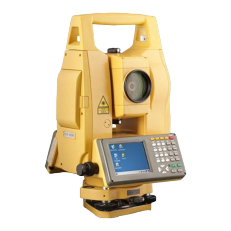
South
South NTS-960R User manual
Popular Measuring Instrument manuals by other brands
Telwin
Telwin DV300 instruction manual

CharlesWater
CharlesWater Jewel 99135 Installation, operation and maintenance
Sartorius
Sartorius MA35 operating instructions

Agilent Technologies
Agilent Technologies B1500A Self-paced training manual
Zoom
Zoom ZF8N Operation manual

Toptica
Toptica FemtoFiber smart manual

