manuals.online logo
Brands
  1. Home
  2. •
  3. Brands
  4. •
  5. Speakman
  6. •
  7. Plumbing Product
  8. •
  9. Speakman SBS-1042 User manual

Speakman SBS-1042 User manual

INSTALLATION INSTRUCTIONS
SBS-1042
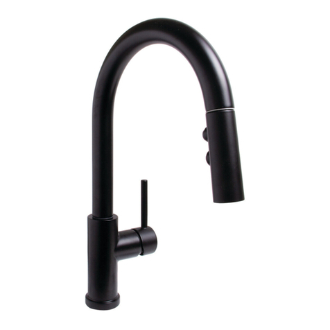
Sensor Kitchen Faucet
92-SBS-1042-03
800-537-2107 www.speakman.com
NEED HELP?
For additional assistance or service please contact:
TOOLS & SUPPLIES NEEDED
Pencil
Eye Protection
Phillips
Screwdriver
Drill Mounting
Hardware
(included)
Measuring
Tape
Adjustable
Wrenches
5 Gallon
Bucket
Drill Bit
Aerator Wrench
(included)
IMPORTANT
MAINTENANCE:
Your new product is designed for years of
trouble-free performance. Keep it looking new
by cleaning it periodically with a soft cloth. Avoid
abrasive cleaners, steel wool, and harsh
chemicals as these will dull the finish and void
your warranty.
See Maintenance section of this document for
additional information.
SAFETY TIPS:
Be sure to read and understand all instructions
before beginning installation.
Inspect all connections after installation.
Cover the drain to avoid loss of parts.
Be sure to wear proper eye protection.
NOTE:
This installation manual covers several
models of Faucets. While the appearance of
your product may differ from those shown, the
installation method is the same.
1Verify the Rubber Washer is seated in the
base of the Faucet. If not, place the
Rubber Washer over hoses and align to
base of Faucet.
2Place Hoses and Wiring, one at a time
through the mounting deck. If installing an
optional Deck Plate, position Hoses and
Wiring through the Deck Plate first.
3From below, slide Easy Mount Nut over
Hoses and Wiring. Position Easy Mount
Nut on to the Faucet Shank
4
A
B
MOUNTING THE FAUCET
Push upward on the Easy Mount Nut until
it makes contact with the underside of the
mounting surface (A). Rotate and hand
tighten into position (B).
A
B
CONNECTION TO WATER SUPPLY
5Locate the 2 Inlet Hoses that contain Inlet Adapters. Make connections to existing HOT and
COLD Supply Stops. The Inlet Hoses are 9/16”-24 UNF and will accept a 3/8” Compression
Fitting. First loosen connection between Adapter (A) and Hose End (B) so each can rotate.
Wrench tighten Adapters to Supply Stops then wrench tighten Hose Ends to the Adapters . The
Hoses are interchangeable for HOT and COLD connections. Desired connection can be
determined later in the “Temperature Adjustment” section of the manual.
6
1 Minute
FLUSH SYSTEM
Locate the remaining Hose that has a
female end as shown below. Place this
Hose into a bucket. Turn on HOT and
COLD water supplies. Open Faucet
Handle and allow water to run from the
Hose and into the bucket for 1 minute.
7
DRY CONNECTION ONLY!
DO NOT USE ANY THREAD SEALANT ON THIS CONNECTION
CONNECT HOSE TO SOLENOID
Turn OFF water supplies. Assemble the
previously flushed Hose to the Inlet of the
Solenoid. Wrench tighten connection.
LEFT OR RIGHT
OF CENTER
10”-12”
16”-20”
DETERMINE MOUNTING LOCATION OF SOLENOID
8Place the Solenoid Assembly against the
desired mounting surface while ensuring
adequate clearance for servicing of all
connections. If using the optional AC
Adapter, consider the distance to the
nearest electrical outlet. Solenoid Assembly
should be mounted so the inlet and outlet
ports are aligned vertically. Mark location of
Solenoid Assembly on the mounting
surface using a pencil, following the
dimensions shown.
DETERMINE MOUNTING LOCATION OF SOLENOID (CONTINUED)
9Remove Mounting Bracket from Solenoid Assembly. Using the previously marked location on
mounting surface, align Mounting Bracket horizontally to approximate position and mark the
mounting locations with a pencil. If mounting on drywall and not to stud, use appropriate anchors
and fasteners for application. Recommend included screw in easy anchor or equal for drywall.
MOUNTING SOLENOID
10
After securing the Bracket to the mounting surface, align and slide Solenoid Assembly over
Mounting Bracket.
11
CONNECT HOSE TO SOLENOID
Connect the Spray-head hose to the outlet
of the Solenoid. This is a push-to-connect
connection. Make sure to push the Hose
completely onto the Solenoid outlet fitting.
12
CONNECT SENSOR TO SOLENOID
Plug in Sensor Eye to Solenoid. Match up
the colors. Blue to Blue, Green to Green.
Ensure the White Stripe on the Male Plug
is aligned to the White Stripe on the
Female Plug.
A
B
INSTALL BATTERIES
13
Access the Interior Battery Enclosure by pressing down on the tab to release the tray holding the
batteries (A). Pull out Battery Tray (B). Insert or replace the batteries with six (6) new standard
1.5v AA batteries (C). Ensure the position of the new batteries are aligned to the plus (+) and
minus (-) symbols within the battery holder.
A
A
IF CONVERTING TO AC POWER (NON INCLUDED OPTION)
14
Verify that no batteries are present within the battery enclosure (A). Connect the AC Adapter to the
Solenoid Body (B). Plug the AC Adapter into the wall outlet. The AC light (C) should illuminate.
15
SECURE BATTERY TRAY
Reinstall the Battery Tray. Make sure to
press the indicated location until the
battery door is fully seated and locks into
position.
A
B
INSTALL WEIGHT
16
Position the Hose Clip above the bottom of the Hose loop (recommended height is 19.5” to 21.5”
below counter) and snap over Hose (A). Position Weight over Hose and slide down on to Hose
Clip (B). Press Weight down firmly on to Hose Clip to secure into position.
17
VERIFY PULL DOWN OPERATION
Pull down Spray-head and check for
smooth operation. Adjust weight and
routing of Spray-head Hose as needed.
TURN ON WATER SUPPLIES
18
Inspect all Hoses for any possible kinks. Turn “ON” water supplies. Inspect for leaks. Adjust
connections as necessary.
19
TO ACTIVATE WATER FLOW
Adjust Handle to the open position (A).
Wave Hand over Sensor Eye once to
activate Solenoid and begin water flow (B).
20
MORE
WATER
LESS
WATER
TO ADJUST FLOW
To adjust the amount of water exiting the
Faucet, tilt the Handle inward or outward.
21
ADJUST
TEMPERATURE
TO ADJUST TEMPERATURE
To adjust the temperature of water exiting
the Faucet, place Handle in the open
position, and rotate the Handle forward or
rearward.
A
B
REVERSAL OF TEMPERATURE ADJUSTMENT
22
This Faucet has the ability for the user to choose the temperature adjustment direction of the
Handle. If the installed temperature adjustment direction of the Handle is opposite from your
preference (Cold when handle is rotated forward, Hot when rotated rearward, or vice versa). Turn
OFF the water supplies and reverse the Inlet Hose connections.
23
NOTE: SENSOR FAUCET WILL ONLY OPERATE
WITH THE HANDLE IN THE “OPEN” POSITION.
DAILY OPERATION
Place Handle in the “OPEN” position.
Activate Faucet and adjust flow and
temperature to desired settings. Wave
Hand across Sensor Eye again to turn off
Faucet. Leave Handle in the set position
for next use.
1In the unlikely event of the Sensor or Solenoid not working properly, a Manual Bypass switch is
located on the Solenoid Box. To bypass the Solenoid control, simply turn off water supply and
rotate the dial with a coin counterclockwise until it stops.
2When Manual Bypass is engaged, the
Faucet will operate like a standard
non-sensor Faucet. Use the Handle to
operate.
3
MANUAL BYPASS
To disable the Manual Bypass, turn the
switch dial clockwise when the water
supply is shut off.
TROUBLESHOOTING
If water flow from the Faucet decreases:
1) Make sure the supply stops and the handle are fully open.
2) Remove the Aerator from the spout using the outlet wrench. Operate the Faucet with outlet device removed. If
water flow is acceptable, disassemble the outlet device and rinse components with clean water.
If no water flows from the Faucet, and If you can hear a clicking sound of Solenoid opening, but no water flows:
1) Verify that the HOT and COLD wall stops and the handle are completely open.
2) If the Battery Light within the Sensor Eye or Solenoid blinks continuously, even when the Faucet is not in use, the
batteries within the Solenoid have low voltage and need replacement.
3) Verify that the In-Line Filter in the Solenoid is not blocked by debris. Clean filter if needed.
If you do not hear a clicking sound of Solenoid opening and no water flows:
1)
Verify that there is no object within 2.5"(65mm) of the sensor window. If the Battery Light within the Sensor Eye blinks
continuously, even when the Faucet is not in use, the batteries within the Solenoid have low voltage and need replacement.
2) Unplug connections to Solenoid for 2 minutes. Plug connections back in. The red light on the Sensor should turn
on for several seconds before becoming operational. If not, check power supplies and connections.
3) Disconnect the existing Solenoid Assembly and connect a new Solenoid Assembly.
Activate the Sensor and check for water flow. If the water flows, the existing Solenoid Assembly should be replaced.
If the batteries have been replaced, but the Faucet still does not operate:
1) Check the battery polarity and electrical connections. Make sure all electrical connections are fully inserted.
2) If the Faucet does not operate, replace the existing Solenoid Assembly with one you know to be functioning.
If the water will not shut off:
1) Verify that the manual bypass located on the solenoid assembly is switched off
2) Let the faucet run for 240 seconds and the solenoid should automatically close.
3) If it is a new installation and still not working, replace the Solenoid Assembly.
QUESTIONS AND ANSWERS
Q. How does the Sensorflo®Faucet work?
A. It uses laser technology. The Sensor emits a non-visible beam of light.
Q. Is the Sensorflo®Faucet sensor beam adjustable?
A. No, the Sensorflo®Faucet sensor beam is not adjustable. It has been factory set to factory
specifications for these Faucets.
Q. The finish on my Faucet seems to be deteriorating. What can I do to prevent this from happening?
A. Many commercial cleaning products contain harsh chemicals and abrasives. These products should
not be used on any chrome-plated plumbing products. Please use only mild soap and water to clean
the Faucet. Dry immediately with a soft cloth.
Q. Is my Faucet protected from power surges?
A. Yes, Sensorflo®has been designed to have built-in power surge protection.
Q. If we lose power, do I have to do something to get the Faucet to operate again?
A. After a power outage, the Faucet is automatically ready for operation as soon as the power comes back on
.
Q. If I call a plumber to come and install this Faucet, will they know enough to hook it up?
A. Our installation diagrams are very easy to follow.
MAINTENANCE
1) Your SENSORFLO®Faucet is designed and engineered in accordance with the highest
quality and performance standards. With proper care, it will provide years of hygienic and
trouble-free service.
2) Periodically, the Faucet will require some minor maintenance to keep it at peak performance. There are
2 low battery indicator lights. One located on the Sensor on the Faucet body and the other located on
the Solenoid Box. When the low battery light on the Sensor blinks, it indicates that the battery is low.
However, the Solenoid can still function at this point. When the low battery light on the Solenoid blinks,
the Solenoid will stop functioning at this point and the batteries need to be replaced immediately. To
replace the batteries, follow the installation instructions in the electrical connections section of this
document.
3) Periodically clean the In-Line Filter.
4) The finish of your Faucet should be cleaned using mild soap and warm water.
5) Dry immediately with a soft, clean cloth for best results.
6) NEVER use abrasive cleaners, chemicals, alcohol or other solvents. They may damage the surfaces of
the non-chrome plated finishes.
PRODUCT WARRANTY
With exception of items listed below, this product has a limited warranty against defects in
materials or workmanship for the period listed below from the date of purchase.
Consumer/Residential: Limited Lifetime Warranty
Commercial Use: 5 Year Limited Warranty
Warranty is limited to replacement of defective components or units.
Associated replacement or repair labor costs are NOT included. This warranty only pertains to single
dwelling residential use. Products used for other than single dwelling residential use are covered by a 5
year limited warranty from the date of purchase.
CALIFORNIA PROPOSITION 65
CALIFORNIA PROPOSITION 65:
WARNING: This product can expose you to chemicals including lead, which is known
to the State of California to cause cancer and birth defects or other reproductive harm.
For more information go to www.P65Warnings.ca.gov.
Wash hands after installation, repair, or removal of this product.
RPG76-115361
REPLACEMENT SOLENOID
RPG76-107259
A/C CONVERSION KIT
(120VAC TO 6VDC)
RPG05-112989
SPRAY HEAD ASSEMBLY
(POLISHED CHROME)
RPG05-112989-SS
SPRAY HEAD ASSEMBLY
(STAINLESS STEEL)
RPG05-112989-MB
SPRAY HEAD ASSEMBLY
(MATTE BLACK)
RPG05-112989-AB
SPRAY HEAD ASSEMBLY
(AGED BRASS)
RPG05-108762
CARTRIDGE
REPAIR PARTS
COMPLIANCE
CONNECTIONS
ASME A112.18.1
CSA B125.1
NSF/ANSI 61/372
CEC
3/8” Compression Inlets
(9/16”-24 UNF)
ROUGH-IN DIAGRAM
DIMENSIONS SUBJECT TO CHANGE WITHOUT NOTICE.
FLOW
1.8 gpm (6.8 L/min)
45
16
"
110mm
21
16
"
53mm
215
16
"
74mm
MAX DECK
THICKNESS
11
2
"
[33mm]
MIN DECK HOLE SIZE
COUNTER WEIGHT
SOLENOID INLET
3/8" COMPRESSION
SOLENOID OUTLET
QUICK CONNECT FITTING
SPRAYHEAD INLET
CONNECT TO SOLENOID OUTLET
QUICK CONNECT FITTING
47" (1200mm) LONG
HOT/COLD INLET
3/8" COMPRESSION
24"(610mm) LONG
MIXED WATER OUTLET
CONNECT TO SOLENOID INLET
3/8" COMPRESSION
24"(610mm) LONG
*NOT TO SCALE
2in
10 11
16
"
272mm
51mm
MIN TO WALL
2in
51mm
MIN TO SINK LEDGE
91
16
"
230mm
713
16
"
199mm
15 3
4
"
400mm
33
8
"
85mm

Other Speakman Plumbing Product manuals

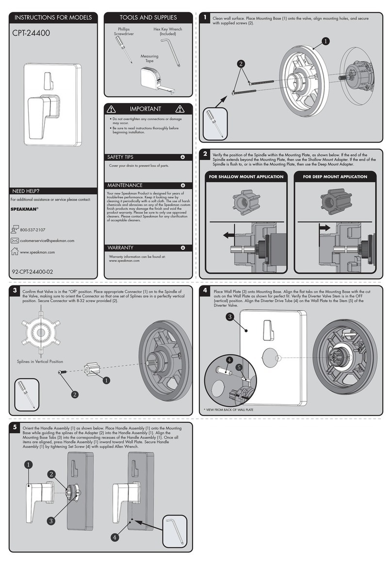
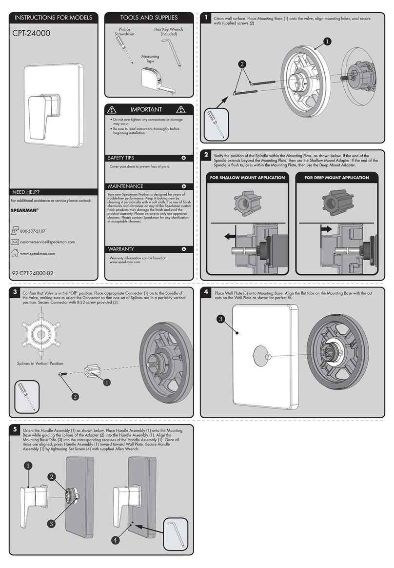
Speakman CPT-24000 User manual

Speakman

Speakman CPT-24000 User manual

Speakman SA-2203 User manual

Speakman

Speakman SA-2203 User manual

Speakman VS-2054 User manual

Speakman

Speakman VS-2054 User manual

Speakman CPT-27000 User manual

Speakman

Speakman CPT-27000 User manual

Speakman SB-1004 User manual

Speakman

Speakman SB-1004 User manual

Speakman EYESAVER SE-570 Guide

Speakman

Speakman EYESAVER SE-570 Guide

Speakman SENTINELPRO COMBINATION SLV-5420 Guide

Speakman

Speakman SENTINELPRO COMBINATION SLV-5420 Guide

Speakman SB-2701 User manual

Speakman

Speakman SB-2701 User manual

Speakman CPT-25001 User manual

Speakman

Speakman CPT-25001 User manual

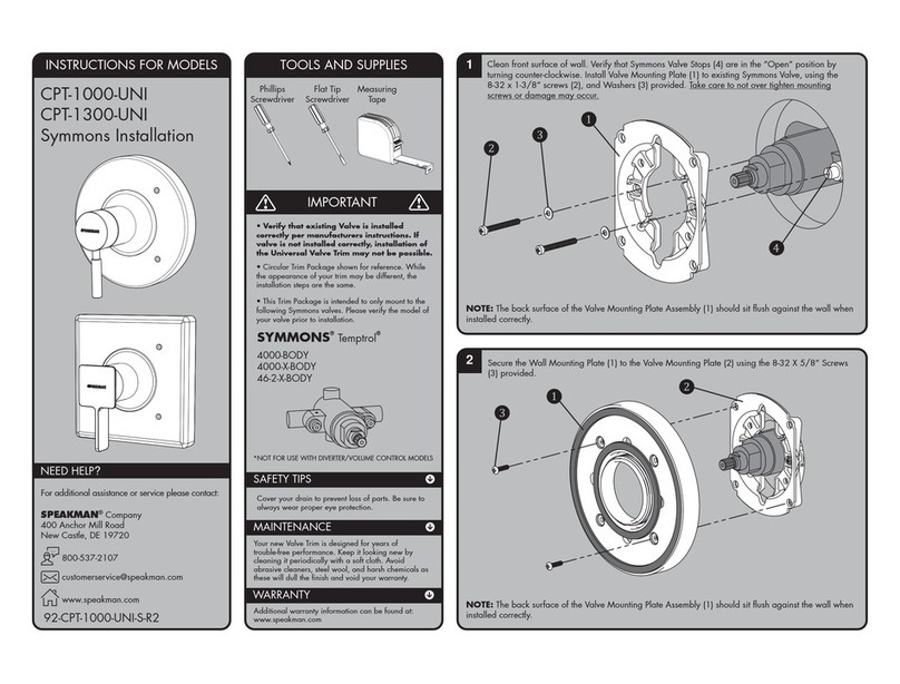
Speakman Symmons CPT-1000-UNI User manual

Speakman

Speakman Symmons CPT-1000-UNI User manual

Speakman Speakman SFS-8000 User manual

Speakman

Speakman Speakman SFS-8000 User manual

Speakman S-9020 Guide

Speakman

Speakman S-9020 Guide

Speakman GRAVITYFLO SE-4320 User manual

Speakman

Speakman GRAVITYFLO SE-4320 User manual

Speakman SB-2401 User manual

Speakman

Speakman SB-2401 User manual

Speakman S-8700 User manual

Speakman

Speakman S-8700 User manual

Speakman CPT-1000-TP User manual

Speakman

Speakman CPT-1000-TP User manual

Speakman VS-2054 Guide

Speakman

Speakman VS-2054 Guide

Speakman CPT-27400 User manual

Speakman

Speakman CPT-27400 User manual

Speakman SB-1002 User manual

Speakman

Speakman SB-1002 User manual

Speakman CPT-1000-P User manual

Speakman

Speakman CPT-1000-P User manual

Speakman SEF-9200 User manual

Speakman

Speakman SEF-9200 User manual

Speakman S-1496-AF User manual

Speakman

Speakman S-1496-AF User manual

Speakman SE-700 Operating and maintenance manual

Speakman

Speakman SE-700 Operating and maintenance manual

Speakman SB-2534 User manual

Speakman

Speakman SB-2534 User manual

Popular Plumbing Product manuals by other brands

Hansa MEDIPRO 0271 0000 Mounting and operating instructions

Hansa

Hansa MEDIPRO 0271 0000 Mounting and operating instructions

Delta 132900 parts manual

Delta

Delta 132900 parts manual

American Standard Heritage Bidet 5034 installation instructions

American Standard

American Standard Heritage Bidet 5034 installation instructions

WimTec SMART HyPlus Assembly and operating instructions

WimTec

WimTec SMART HyPlus Assembly and operating instructions

Mira Vie Installation and user guide

Mira

Mira Vie Installation and user guide

American Standard Lakeland 4114.100 installation instructions

American Standard

American Standard Lakeland 4114.100 installation instructions

Graff G-11210-LM55B installation instructions

Graff

Graff G-11210-LM55B installation instructions

Glacier bay FSU1Z2719A1 SA1 Use and care guide

Glacier bay

Glacier bay FSU1Z2719A1 SA1 Use and care guide

Saunatec IG-820-SH/S820 user manual

Saunatec

Saunatec IG-820-SH/S820 user manual

Helvex LIQUIDA TV-302 installation guide

Helvex

Helvex LIQUIDA TV-302 installation guide

Hans Grohe AXOR Select 18311181 Assembly instructions

Hans Grohe

Hans Grohe AXOR Select 18311181 Assembly instructions

iB HERMES 306 Fitting instructions

iB

iB HERMES 306 Fitting instructions

T&S B-0665-BST Series Installation and maintenance instructions

T&S

T&S B-0665-BST Series Installation and maintenance instructions

Whitehall 8193 Installation, operation & maintenance manual

Whitehall

Whitehall 8193 Installation, operation & maintenance manual

Lefroy Brooks K1-4302 Installation, operating,  & maintenance instructions

Lefroy Brooks

Lefroy Brooks K1-4302 Installation, operating, & maintenance instructions

Axor Citterio E 36413 1 Series Installation/User Instructions/Warranty

Axor

Axor Citterio E 36413 1 Series Installation/User Instructions/Warranty

Geberit Monolith 131222SI5 installation manual

Geberit

Geberit Monolith 131222SI5 installation manual

Kohler K-T12014 Homeowner's guide

Kohler

Kohler K-T12014 Homeowner's guide

manuals.online logo
manuals.online logoBrands
  • About & Mission
  • Contact us
  • Privacy Policy
  • Terms and Conditions

Copyright 2025 Manuals.Online. All Rights Reserved.