Specac Gateway GS11155 User manual
Gateway™ ATR Electrically
Heated Trough Top Plate
User Manual
2I-11155-16

List of Safety Symbols
Safety Symbol
Meaning
General Caution.
(Reference ISO 7000-0434B, 2004-01)
Caution – Hot Surface.
Reference IEC 60417-5041, 2002-10)
Caution – Possibility of Electric Shock
Indoor Use Only
Electrical Safety
Warning: The temperature controller supplied with the this
accessory is Class 1 (earthed) construction and must be
connected to an earthed mains socket outlet.
Warning: Disconnect the mains from the temperature
controller before cleaning. Clean only with a soft cloth,
lightly moistened with water.

Gateway™ ATR Electrically
Heated Trough Top Plate
User Manual
2I-11155-16

User Manual
2
Gateway™ ATR Electrically Heated Trough Top
Plate P/N GS11155
CONTENTS
1. INTRODUCTION ................................................................................. 3
2. SAFETY CONSIDERATIONS ................................................................ 5
3. UNPACKING AND CHECKLIST ............................................................. 6
4. ALIGNMENT OF THE GATEWAY™ ATR HEATED TROUGH TOP PLATE .. 7
FITTING THE GATEWAY™ ATR HEATED TROUGH TOP PLATE ............. 8
5. ANALYSING DIFFERENT SAMPLE TYPES ........................................... 10
LIQUID SAMPLING ........................................................................... 10
PASTE SAMPLES ............................................................................ 11
SEMI-SOLID SAMPLES (FILMS) ........................................................ 12
6. ATR CRYSTAL REMOVAL AND REPLACEMENT .................................. 14
CRYSTAL REMOVAL FROM THE HEATED TROUGH TOP PLATE ............ 14
CLEANING THE KALREZ GASKET ...................................................... 16
REPLACING THE CRYSTAL IN THE TOP PLATE ASSEMBLY .................. 18
CLEANING THE GATEWAY™ ATR HEATED TROUGH TOP
PLATE INTACT................................................................................ 19
NOTES ON CLEANING ...................................................................... 20
DATA SHEET FOR ZINC SELENIDE .................................................... 22
DATA SHEET FOR GERMANIUM ........................................................ 23
DATA SHEET FOR SILICON .............................................................. 24
7. GATEWAY™ ATR HEATED TROUGH TOP PLATE OPERATING
PARAMETERS ................................................................................. 25
8. GATEWAY™ ATR HEATED TROUGH TOP PLATE "BUBBLE NUMBER"
PART IDENTIFICATION ..................................................................... 27
9. GATEWAY™ ATR HEATED TROUGH TOP PLATE SPARE PARTS ........ 27
10. GATEWAY™ ATR TECHNICAL SPECIFICATION… ............................. 28
11. GATEWAY™ ATR HEATED TROUGH TOP PLATE SERIAL NUMBER ... 29
© April 2016 Specac Ltd. All rights reserved.
Brilliant Spectroscopy is a trademark of Specac Ltd.
Other product names mentioned herein may be trademarks
of their respective owners.

Gateway™ ATR Electrically Heated Trough Top Plate
3
1. Introduction
Thank you for purchasing a Specac Product.
This user instruction manual for the Gateway™ ATR Electrically
Heated Trough Top Plate P/N GS11155 is to be used in conjunction
with the user instruction manual provided for the Gateway™ 6
Reflection ATR Accessory against P/N GS11165 (2I-11165-4).
Understanding of the Gateway™ ATR Accessory itself helps in usage
of any alternative ATR Top Plates that are compatible with this ATR
system.
The Gateway™ ATR Electrically Heated Trough Top Plate P/N
GS11155 is an alternative Top Plate that can be used on the optical
unit (P/N GS11170) of the Gateway™ ATR Accessory. The Gateway™
ATR Accessory supplied as standard for a kit of parts under P/N
GS11165, provides for an optical unit (GS11170), a trough top plate
assembly fitted with a 45° ZnSe crystal (GS11166), a flat top plate
assembly fitted with a 45° ZnSe crystal (GS11133) and a clamp
assembly (GS11171). (See user instruction manual 2I-11165-3).
Note: Any Gateway™ ATR Top Plate assembly can also be used on
older Benchmark™ ATR optical units, P/N’s GS11160, GS11110
and GS11180.
Using the Gateway™ ATR Electrically Heated Trough Top Plate in
conjunction with any of the above optical unit systems, a liquid sample
can be held static over a 6 Reflection event ATR crystal to be studied
from ambient up to 200°C temperatures, the temperature being set in
1°C steps over the entire range. Chemical interactions for the mixing of
sample species at varying temperatures may also be monitored. (e.g. a
solid sample can be deposited onto the ATR crystal and a fluid can be
placed over the sample to observe any changes spectroscopically.)
Power is applied to raise the temperature of the Top Plate assembly by
use of a dedicated 4000 Series™ Temperature Controller. A separate
user instruction manual is supplied for use and understanding of the
controller to operate the Heated Top Plate assembly.
User Manual
4
Usually, a liquid sample to be analysed is just simply placed to cover
over the ATR crystal analysis area of the Trough Top Plate assembly.
However, thin polymer films or semi-solid type samples can also be
analysed spectroscopically if the film is cut to the approximate size of
the crystal surface area and the Gateway™ ATR clamp assembly
mechanism is employed. A PTFE pressure pad piece is supplied to
enable this type of sampling to be carried out.
The Gateway™ ATR Electrically Heated Trough Top Plate has been
designed with the capability to remove the ATR crystal for thorough
cleaning or using a replacement ATR crystal material in the Top Plate
if desired. Any of the crystal materials usable with the Gateway™ ATR
system – ZnSe, germanium or silicon – can be placed into the
Gateway™ ATR Electrically Heated Trough Top Plate, although
germanium loses its spectral IR transmission capability with a
progressive rise in temperature, becoming completely opaque at
temperatures of circa 100°C and above.
As a standard offering for P/N GS11155, a 45° angle ZnSe crystal (P/N
GS11145) is fitted. The ATR crystal options are:
P/N GS11145 - Gateway™ ZnSe crystal, 45° angle.
P/N GS11146 - Gateway™ Silicon crystal, 45° angle.
P/N GS11147 - Gateway™ Germanium crystal, 45° angle.
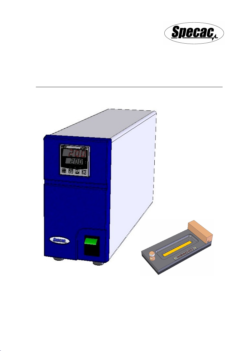
Fig 1. Gateway™ ATR Electrically Heated Trough Top Plate

Gateway™ ATR Electrically Heated Trough Top Plate
5
2. Safety Considerations
With use of any spectroscopic accessory that involves the study of a
wide range of chemical samples, the associated risk in handling may
mostly be attributed to the specific sample type to be handled itself. As
far as it possible you should follow a procedure for safe handling and
containment of the type of sample to be used.
With respect to safety of use specifically to the Gateway™ ATR
Accessory, this uses different crystal materials for the ATR crystal
Trough, Flat and Flow Through Top Plate assemblies where a sample
is bought into contact for analytical spectroscopic study. As standard,
Zinc Selenide (ZnSe), germanium (Ge) and Silicon (Si) are the three
crystal materials of choice that can be used.
Caution: Out of these three different crystal types, ZnSe is
the most potentially hazardous material with respect to
toxicity risk in use and handling.
Both Ge and Si crystal materials can be considered relatively safe to
use, although Ge may be harmful to the body if it is ingested in
significant quantity. The general rule when working with any crystal
material (and sample) is to always wear gloves and safety gear (e.g.
safety spectacles) when handling to obviate the risk of contact with the
skin.
Provided with each ATR crystal version of top plate assembly is a
window material safety data sheet for the crystal material itself that can
be consulted for safe handling. A copy of each of these datasheets can
also be found in the Gateway™ ATR instruction manual (2I-11165-4) in
the Notes on Cleaning Section found on pages 42, 43 and 44.
General Operational Safety Use
Caution: Always follow local laboratory safety protocols
and procedures when using potential toxic or flammable
substances with this equipment. The equipment is
intended for use by suitably trained personnel only.
User Manual
6
Caution: No user serviceable parts within the temperature
controller supplied, contact the manufacturer or approved
service agent for advice if the product is not functioning
correctly or is visibly damaged.
Caution: If the equipment is used in a manner not
specified by the manufacturer, the protection provided by
the equipment may be impaired
Warning: Risk of burns when operated at high
temperatures on accessible parts surrounding the heated
assembly.
End of Lifetime Equipment Use
If any parts have reached their limit of lifetime and need to
be replaced, use appropriate WEEE and other local
regulations for the safe disposal of electrical equipment
and toxic chemicals.

Gateway™ ATR Electrically Heated Trough Top Plate
7
3. Unpacking and Checklist
The Gateway™ ATR Electrically Heated Trough Top Plate and its
dedicated 4000 Series Temperature Controller are supplied packed in
a black plastic carry case and cardboard box respectively.
The carry case contains the following:
Electrically Heated Trough Top
Plate with Zinc Selenide crystal
(or as specified from germanium
and silicon options) and integral
power/thermocouple connectivity
cable.
ATR spectrum of the crystal as fitted to the Top Plate assembly to
show its background throughput.
PTFE pressure bar.
Plastic spatula.
Allen Key (2.5mm A/F)
The cardboard box contains the following:
4000 Series Temperature Controller
dedicated for control of the Gateway™
ATR Electrically Heated Top Plate.
Appropriate mains power cable.
Instruction manual for the 4000 Series
Temperature Controller.
Remove the items carefully from their packaging in preparation for
installation and use.

User Manual
8
4. Alignment of the Gateway™ ATR Electrically
Heated Trough Top Plate
The Gateway™ ATR Electrically Heated Trough Top Plate is to be
installed onto the optical unit (GS11170) of the Gateway™ ATR
Accessory for operation in the study of static liquids or semi-solid
samples and thin films over the temperature conditions from ambient to
200°C. This Trough Top Plate should be optimised for its energy light
throughput from a particular alignment of the mirrors on the optical
when installed for use.
If the Gateway™ ATR Accessory (as the Kit GS11165) is available for
use, please follow the instruction manual supplied (2I-11165-4) for the
alignment procedure to optimize the liqht energy throughput of the ATR
system on your particular spectrometer using either the Trough Top
Plate (GS11166) or Flat Top Plate (GS11133) assembly as supplied.
The input and output mirror settings for their rotation and tilt angles will
be established on the optical unit (GS11170) from the alignment
procedure using either of these two Top Plates.
When subsequently placing the Electrically Heated Trough Top Plate
onto the optical unit as a replacement for either the Trough (GS11166)
or Flat (GS11133) Top Plate assembly, a signal throughput will be
registered, but it is possible the mirrors in the optical unit may require
slight re-adjustment for an optimum throughput to be established in
use of this alternative Trough Top Plate. Follow the alignment
procedure with the Electrically Heated Trough Top Plate in position to
obtain the best throughput energy signal for the spectrometers system.
Note: If just the Gateway™ optical unit (GS11170) and an Electrically
Heated Trough Top Plate are available to use, unless the optical
unit has been pre-aligned to register some energy throughput
with a Top Plate in position, then it may be difficult to gain an
optimum alignment using the FTIR spectrometer systems energy
source and detection system. A rough pre-alignment is to be
established with the optical unit and Electrically Heated Trough
Top Plate in position using a visible light source such as the
Laser Alignment Accessory (P/N GS24500).
Gateway™ ATR Electrically Heated Trough Top Plate
9
Fitting the Gateway™ ATR Electrically Heated Trough Top
Plate
The Gateway™ ATR Electrically Heated Trough Top Plate fits onto the
top of the Gateway optical unit via alignment of the round hole (1) and
slot hole (2) on the underside of the Top Plate over the two fixing
location pins (3) on the optical unit. (See Fig 2 and Fig 3.)
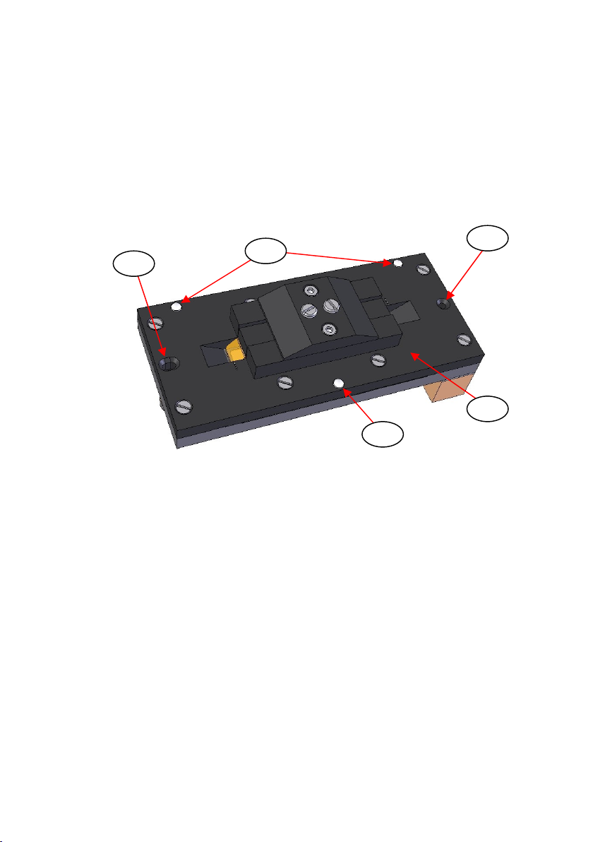
Fig 2. Round and Slot Location Holes on Underside of
Gateway™ ATR Electrically Heated Trough Top Plate
The Gateway™ ATR Electrically Heated Trough Top Plate is fitted and
positioned the correct way around on the optical unit when the round
hole (1) is placed over the right side location pin (3R) and the slot hole
(2) is placed over the left side location pin (3L) as viewed from the
front of the optical unit. The main body plate (4) of the Top Plate
assembly should be resting on its three PTFE stand-off feet (5) onto
the top surface of the optical unit when properly located.
Note: To maintain a correct optical alignment for consistency of optical
throughput energy of the Gateway™ ATR Electrically Heated
Trough Top Plate, it should always be placed onto the optical
unit the same way around after removal for cleaning or crystal
replacement etc, with the round (1) and slot (2) holes fitting over
their correct and respective fixing location pins (3R) and (3L).
2
1
4
5
5

User Manual
10
Important: Care must also be taken to see that from installation there
is no unnecessary stress or strain applied to the integrally
fitted power/thermocouple cable, which could cause
damage to the thermocouple. Avoid sharp bends of this
cable at the end attached to the Heated Trough Plate.
Fig 3. Fitting of Gateway™ ATR Electrically Heated Trough
Top Plate to the Gateway™ Optical Unit
1
2
4
3L 3R
R

Gateway™ ATR Electrically Heated Trough Top Plate
11
5. Analysing Different Sample Types
When the Gateway™ ATR Electrically Heated Trough Top Plate has
been correctly installed onto the optical unit and aligned, then its
integral power and thermocouple cable assembly with the six-way
bayonet plug of the Top Plate assembly is to be connected to its
appropriate socket at the rear of the 4000 Series Temperature
Controller. The bayonet plug is push fitted and turned to click into the
Controllers socket connection.
Note: Please refer to the instruction manual supplied for the 4000
Series Controller to make the connection and how to heat and
control the temperature to the Electrically Heated Trough Top
Plate assembly.
In operation for collection of a background spectrum and then a
sample spectrum (see Spectral Collection Using the Gateway™ ATR
Accessory from the instruction manual 2I-11165-3), ideally the
temperature conditions for both spectral acquisitions should be the
same. The parameters of operation for the Electrically Heated Trough
Top Plate have been specifically set on its 4000 Series Controller to
allow for a maximum temperature rate rise of 10°C per minute. Any
higher rate rise risks introducing thermal shock to the ATR crystal (6) in
the Top Plate assembly and causing damage. For the parameter listing
set on the supplied 4000 Series Controller, please refer to section 7),
pages 25 and 26 of this user instruction manual.
Liquid Sampling
Liquids can be poured onto the crystal (6) of the Gateway™ ATR
Electrically Heated Trough Top Plate or introduced by the use of a
pasteur pipette.
The liquid should cover the entire ATR crystal (6) surface where the
sample is being heated. It is important that a sufficient volume of
sample is applied so that the crystal (6) is not left exposed during any
spectral measurement, if there is any vaporization of the sample
because of an elevation in the temperature above ambient conditions.

User Manual
12
As much of a liquid sample should be removed from the crystal (6)
area with a pasteur pipette when the Heated Trough Top Plate
assembly is cool to touch if any elevated temperature measurements
have been taken. It is recommended that the Heated Trough Top Plate
is also removed away from the optical unit to a safe area for cleaning
before introducing the next sample or after use. This prevents potential
accidental contamination of the optical unit parts and the sample
compartment area of the spectrometer.
Note: Removal of the Top Plate assembly from the optical unit to clean
in a safe working area may also require disconnection of its
power and thermocouple cable from the 4000 Series Controller.
If the liquid sample solidifies against the ATR crystal (6) when the Top
Plate assembly cools from an elevated temperature measurement, it
may be easier to remove most of the sample when hot, by very
carefully using the pipette and wiping the remainder of any sample
away from the ATR crystal (6) with a soft lens cleaning tissues while
cooling. Remove the last traces of the sample when the Top Plate
assembly has cooled sufficiently to handle by using fresh tissues
soaked in a suitable solvent.
Warning: Do not remove the Heated Trough Top Plate for
cleaning when hot as it can cause serious burns.
Paste Samples
Apply the paste lightly to cover the ATR crystal (6) surface completely
using the plastic spatula as supplied.
Similar to liquid sample handling, remove the sample by wiping clean
using a soft lens cleaning tissues when the top plate has cooled
sufficiently. Remove the last traces of the sample by using fresh
tissues soaked in a suitable solvent.
If the paste sample solidifies against the ATR crystal (6) when the Top
Plate assembly cools from an elevated temperature measurement, it
may be easier to remove most of the sample when hot, by very

Gateway™ ATR Electrically Heated Trough Top Plate
13
carefully using soft lens cleaning tissues to wipe the sample clear of
the crystal (6) while cooling. Remove the last traces of the sample
when the Top Plate assembly has cooled sufficiently to handle by
using fresh tissues soaked in a suitable solvent.
Warning: Do not remove the Heated Trough Top Plate for
cleaning when hot as it can cause serious burns.
Semi-Solid Samples (Films)
Although the Electrically Heated Trough Top Plate has been
specifically designed for the ATR measurement of liquid sample types
at elevated temperatures up to 200°C, flexible semi-solid, film type
samples can be analysed by use of this Top Plate with the supplied
PTFE pressure bar (7) and employment of the Gateway™ ATR Clamp
Assembly fitted to the optical unit. (See Fig 4.)
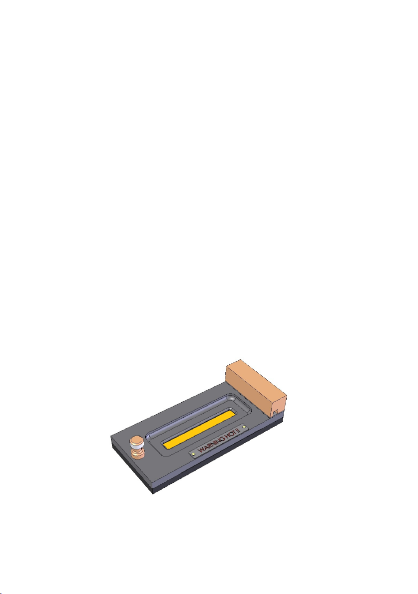
Fig 4. PTFE Pressure Bar Used With Electrically Heated
Trough Top Plate
7
6

User Manual
14
To analyse a semi-solid sample such as a thin film, the film sample
must be prepared by cutting to size to cover over the entire surface of
the ATR crystal (6) in the recess of the trough area. The PTFE
pressure bar (7) is then very carefully placed over the film surface on
top of the crystal (6). The PTFE pressure bar (7) allows for a sufficient
height above the surrounding recessed trough area to transfer the
force that is to be applied from use of the clamp assembly. Please
refer to installation and operation of the clamp assembly when on the
optical unit from the Gateway™ ATR instruction manual 2I-11165-3,
pages 9 to 12.
Exercise great care when sampling for semi-solid types. Apply a
load from the clamp assembly to give sufficient sample contact to
register an ATR spectrum for the sample. Any temperature can be
selected from ambient to 200°C to measure for the sample, but be
careful if the film sample is subject to melting, burning or charring at
elevated temperatures in case of potential subsequent damage to the
Gateway™ ATR Top Plate components and crystal (6).
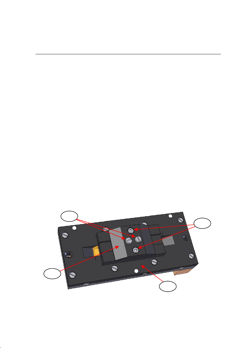
Note: The ATR crystal (6) is held liquid tight against an upper Kalrez
gasket seal (8) in the Gateway™ ATR Electrically Heated
Trough Top Plate by means of spring tensioning screws (9) in a
lower clamp pressure plate assembly (10). Do not apply too
much pressure from the clamp assembly to the crystal (6) as this
could force the crystal (6) to be detached from the upper Kalrez
gasket seal (8) in the main body plate (4) of the Top Plate
assembly. This event would result in loss of any applied heat to
the sample and possible leakage of the entire Top Plate
assembly when subsequently used for any liquid samplings.
Similar to liquid sample handling, after analysis remove the film sample
from the ATR crystal (6) and wipe clean using a soft lens cleaning
tissues when the top plate has cooled sufficiently, if elevated
temperatures have been used in any sample measurements. Remove
any last traces of the sample from the crystal (6) by using fresh tissues
soaked in a suitable solvent.
Gateway™ ATR Electrically Heated Trough Top Plate
15
6. ATR Crystal Removal and Replacement
The design of the Gateway™ ATR Electrically Heated Trough Top
Plate allows for the ATR crystal (6) to be removable for easier cleaning
or if damage occurs and the crystal needs to be replaced.
Crystal Removal from the Heated Trough Top Plate
If it is necessary to remove the crystal (7) for thorough cleaning of the
Top Plate assembly of parts or to replace any damaged parts etc, the
following procedure should be adopted.
Note: It is normally easier to work on the Top Plate assembly having
disconnected the power and thermocouple cable from the 4000
Series Controller.
Important: For safety precautions wear gloves when carrying out
the following procedure.
1) Lay the Top Plate assembly on to a clean workspace area and
proceed to remove the two M3 x 8mm cap head screws (11) from
the lower clamp pressure plate assembly (10) on the underside of
the Top Plate assembly using the 2.5mm A/F Allen key supplied.
Turn the screws (11) anticlockwise to remove. (See Fig 5.)
Fig 5. Underside of Heated Trough Top Plate Assembly
9
11
4
10

User Manual
16
Note: Do not touch the two slot head tensioning screws (9) as these
hold the components of the lower clamp plate assembly (10)
together for containment of the internal springs.
2) Between the underside of the lower clamp plate assembly (10) and
the ATR crystal (6) there is a protective lead pad (12). Carefully
remove the lower clamp plate assembly (10) away to gain access to
the lead pad (12). (See Fig 6.) The lead pad (12) may be stuck
close to the underside of the crystal (6) and so it needs to be
removed very carefully away from the crystal.
Note: The lead pad (12) will be needed in any re-assembly after
cleaning of parts or if replacing with a new crystal (6).
Fig 6. Lead Pad on Underside of ATR Crystal with Removal of
Lower Clamp Pressure Plate Assembly
3) If the lead pad (12) has adhered to the crystal (6), then it may be
easier to remove it carefully away from the crystal when the crystal
4
10
6
12
9
9

Gateway™ ATR Electrically Heated Trough Top Plate
17
(6) itself has been removed from its centralised position in its
recess of the main body plate (4). Therefore, support the crystal (6)
and the lead pad (12), with one hand and turn over the Top Plate
assembly so that the crystal (6) can fall out to drop into the palm of
your hand. If the crystal (6) is also stuck in the main body plate (4)
because of good sealing to the Kalrez gasket (8) on the top
(sampling) surface of the crystal (6), then put a soft pad or tissue on
the work bench area and lay the Top Plate assembly onto it the
same way up as it would be used when fitted to the optical unit.
Try to loosen the crystal (6) away from the Kalrez gasket (8) seal by
exerting a small pressure on either ends of the top of the crystal (6)
from inside the trough area and pushing down from above. Do not
press too hard in case the crystal (6) breaks. (ZnSe, in particular, is
a hard, but brittle crystal material.) If the crystal is stubborn to
movement try to lubricate the internal trough and Kalrez gasket (8)
area by use of some solvent (e.g. methanol) covering the top
surface of the crystal (6) whilst exerting the gentle pressure.
When the crystal (6) and the lead pad (12) have been removed, it may
now be easier to separate the lead pad (12) from the crystal. If the
crystals (6) top sampling surface looks OK and can be cleaned
carefully, then it may not be necessary to remove the lead pad (12)
away for further cleaning prior to re-assembly and use. However, if the
lead pad (12) is to be removed, it may be necessary to immerse the
whole crystal (6) and lead pad (12) assembly in a beaker of water or
methanol solvent and apply a gentle “sonication cleaning” of the items.
The action of the sonic agitation of the solvent may help to loosen the
lead pad (12) away from the crystal such that when the items are
removed from the solvent they can be easily and safely separated
without any damage to the lead pad (12) or crystal (6) parts.
Clean the ATR crystal (6) by following the Notes on Cleaning
instructions on page 20.
Cleaning the Kalrez Gasket Seal
When the ATR crystal (6) has been removed from the Top Plate
assembly, access can be gained to the Kalrez gasket seal (8) for
cleaning if necessary. (See Fig 7.)

User Manual
18
Fig 7. Kalrez Gasket Seal in the Gateway™ ATR
Electrically Heated Trough Top Plate
If a new Kalrez gasket seal (8) is needed, this is specially cut to fit
from Kalrez sheet material. The procedure is best done by Specac as
further dis-assembly of the Top Plate is required to replace a new
Kalrez gasket (8) seal and for re-fitting of a new ATR crystal (6) into
position within the Electrically Heated Trough Top Plate assembly.
Warning: Further dis-assembly of the Top Plate for the Kalrez gasket
(8) replacement exposes electrical components which should
not be touched other than by qualified electrical personnel.
If a new Kalrez gasket (8) is ever required, please contact Specac at
techsupport@specac.co.uk to arrange for return of the item to Specac
to carry out the service.
If however, after removal of the crystal (6) the Kalrez gasket (8) is in
good condition and only requires cleaning, then suitable solvents such
as water, methanol or acetone may be used to moisten a soft lens type
cleaning tissue or cotton bud to wipe around the gasket surfaces.
Note: Specac recommend that with removal or replacement of the
crystal (6), fitting a new Kalrez gasket (8) is the preferred option.
8
4
Table of contents
Other Specac Laboratory Equipment manuals

Specac
Specac Atlas GS15515 User manual

Specac
Specac Quest User manual

Specac
Specac ATMOS A2.5 User manual

Specac
Specac GS12000 Series User manual
Specac
Specac ARROW Instruction manual

Specac
Specac Golden Gate GS10640 User manual

Specac
Specac APEX QUICK RELEASE DIE User manual

Specac
Specac GS20600 User manual

Specac
Specac Selector GS19900 User manual

Specac
Specac Quest User manual

Specac
Specac Atmos User manual

Specac
Specac Quest ATR GS10800 Series User manual

Specac
Specac Atlas GS15640 User manual

Specac
Specac GS10890 User manual

Specac
Specac Gateway ATR User manual

Specac
Specac Golden Gate GS10500 Series User manual

Specac
Specac Storm 10H User manual

Specac
Specac Gateway ATR User manual


