manuals.online logo
Brands
  1. Home
  2. •
  3. Brands
  4. •
  5. Specac
  6. •
  7. Laboratory Equipment
  8. •
  9. Specac GS20600 User manual

Specac GS20600 User manual

Solids Cell Holders
User Manual
2I-20600,20610 Issue 3
Solids Cell Holders
User Manual
2I-20600,20610 Issue 3
User Manual
2
Solids Cell Holders GS20600 and GS20610
CONTENTS
1. INTRODUCTION ................................................................................. 3
2. CHECKLIST OF CONTENTS ................................................................. 4
3. THE SOLIDS CELL HOLDERS .............................................................. 5
4. LEGEND OF BUBBLE PART NUMBERS…………… ........... ……………10
© April 2016 Specac Ltd. All rights reserved.
Brilliant Spectroscopy™ is a trademark of Specac Ltd. Other product
names mentioned herein may be trademarks of their respective
owners.
Solids Cell Holders GS20600 and GS20610
3
1. Introduction
Thank you for purchasing a Specac product.
The Solids Cell Holders P/N’s GS20600 and GS20610 have been
designed to allow for the study of solid samples at various
temperatures, via transmission spectroscopy ranging from the Far UV
through to the Far IR.
A solid sample is prepared and is fitted into either the P/N GS20600 or
P/N GS20610 Solids Cell Holder. In turn the Solids Cell Holder with its
sample is then fitted into a particular Mount Holder for installation into
the spectrometer sample compartment for spectral measurement. The
specific Mount Holder used will determine the temperature range that
can be applied to the solid sample in the Solids Cell Holder.
The Solids Cell Holders and their associated parts have been made
from brass with a chrome plating finish.
The Solids Cell Holder P/N GS20600 can be used in the following
Specac mount holders:
P/N GS20710 - Water Heating Jacket (Temperature capability of
ambient to 90°C).
P/N GS20730 - Electrical Heating Jacket (Temperature capability of
ambient to 250°C).
P/N GS20740 - Ambient Temperature Cell Holder (Ambient
temperature capability).
The Solids Cell Holder P/N GS20610 can be used in the following
Specac mount holders:
P/N GS20710 - Water Heating Jacket (Temperature capability of
ambient to 90°C).
P/N GS20740 - Ambient Temperature Cell Holder (Ambient
temperature capability).
P/N GS21525 – Variable Temperature Cell (Temperature capability of
-185°C to 250°C).
User Manual
4
2. Checklist of Contents
Check that the following items have been supplied:
 For Solids Cell Holder P/N GS20600.
Body
Pressure Plate
Clamp Ring
Clamp Ring Key
 For Solids Cell Holder P/N GS20610.
Outer threaded cell body
Inner threaded cell body
3 sets/pairs of flat and recessed sample pressure plates
 Instruction manual for the Solids Cell Holder.
Remove the Solids Cell Holder and its specific parts from their
packaging.
Solids Cell Holders GS20600 and GS20610
5
3. The Solids Cell Holders
Solids Cell Holder GS20600
The body of the Solids Cell Holder P/N GS20600 has a fixed size
aperture of 10mm diameter, with an overall outer diameter of 41mm.
Solid samples from 12mm to 28mm diameter and up to 3mm thick can
be inserted into the body to be analysed by transmission spectroscopy.
Fig. 1 Solids Cell Holder GS20600
Solids Cell Holder GS20610
The Solids Cell Holder P/N GS20610 is used specifically in the
Variable Temperature Cell P/N GS21525. This Solids Cell Holder
consists of outer and inner cell threaded bodies and three pairs of
pressure plates. The varying aperture sizes of the pressure plates
enable samples with a diameter of 12 - 17mm, 17 - 22mm and 22 -
30mm and thicknesses of a few microns to 8mm thick to be inserted
into the inner threaded body to be analysed.
Fig. 2 Solids Cell Holder GS20610
User Manual
6
Loading a Solid Sample into the GS20600 Solids Cell Holder
Fig. 3 Exploded view of Solids Cell Holder GS20600
1. Remove the screw retaining ring (1) (turn anticlockwise) from the
Solids Cell Holder body (2) by means of the square key provided.
The square key locates into the slots of the retaining ring (1) (See
Fig.3). The pressure plate (3) will now be accessible. Remove the
pressure plate (3) from the body (2).
2. Insert an appropriate sized solid sample such that it lays flat in the
Solids Cell Holder body (2).
3. Replace the pressure plate (3) onto the solid sample, by placing it
inside the body (2) and aligning it by engagement of the anti-
rotation pin (4). There is a taper to the aperture of the pressure
plate (3), whereby one side has a larger diameter to the aperture
than the other. Ensure that the smaller diameter aperture side of
the pressure plate (3) is in contact with the solid sample.
1 3
2
Solid sample placed in
S
olids
Cell
H
older body
4
9
Solids Cell Holders GS20600 and GS20610
7
4. Replace the retaining ring (1) into the body (2) and tighten (turn
clockwise) by means of the square key. Ensure that the sample is
firmly clamped in the Solids Cell Holder holder, taking care not to
over-tighten in case of damaging the sample.
The Solids Cell Holder P/N GS20600 containing a solid sample is now
ready for use. Removal or replacement of a solid sample in the Solids
Cell Holder is the reverse procedure of steps 1 to 4.
Loading a Solid Sample into the 20610 Solids Cell Holder
Fig. 4 Exploded view of Solids Cell Holder GS20610
There are three matched pairs of different aperture pressure plates (5
and 6) that are used in the assembly of the Solids Cell Holder P/N
GS20610. (See Fig. 4). One of the pressure plates (5) is a location
plate. An appropriate size sample is placed into the recess of the
location plate on the face of the plate as indicated at Fig. 4. The
opposite face of the location plate (5) has a stepped circumference,
which enables the location plate to fit within the outer threaded body
part (7). (See Fig.5).
7 5 6 8
Solid sample placed in
recess of pressure plate
9
User Manual
8
Recessed face Stepped circumference face
Fig. 5 Location plate (5) faces
The three different location plates (5) for the pairs of pressure plates (5
and 6) have apertures of 10mm, 15mm and 20mm diameter. The
corresponding recess diameters for 10mm and 15mm aperture location
plates (5) are 17mm and 22mm diameter respectively, both with a
depth of recess of 1mm. The 20mm diameter aperture location plate
(5) does not have a recess. The face is flat to its overall outside
diameter of 32mm. (32mm is the outside diameter of all three location
plates).
The other pressure plate (6) of the pair is flat on both faces. A
matched, pair of pressure plates (5 and 6) have the same aperture
diameter.
5. Place the correct aperture location pressure plate (5) into the end
of the inner threaded cell body (7) as seen at Fig. 4.
5a. For a solid sample with a diameter between 12mm and 17mm and
up to 8mm thick, place the sample in the recess of the 10mm
diameter location pressure plate (7).
5b. For a solid sample with a diameter between 17mm and 22mm and
up to 8mm thick, place the sample in the recess of the 15mm
diameter location pressure plate (7).
Solids Cell Holders GS20600 and GS20610
9
5c. For a solid sample with a diameter between 22mm and 30mm and
up to 8mm thick, place the sample on the flat face of the 20mm
diameter location pressure plate (7).
6. Put the plain flat pressure plate (6) with the same corresponding
aperture diameter as the location plate (5) on top of the sample.
Ensure that the pressure plates (5 and 6) and the solid sample that
is held between them are well aligned.
7. Place the outer threaded cell body (8) over the inner threaded cell
body (7) holding the pressure plates (5 and 6) and the solid
sample and turn the outer body clockwise until the sample is firmly
located in place. Take care not to over-tighten the assembly in
case of damaging the sample.
The Solids Cell Holder P/N GS20610 containing a solid sample is now
ready for use. Removal or replacement of a solid sample in the Solids
Cell Holder is the reverse procedure of steps 5 to 7.
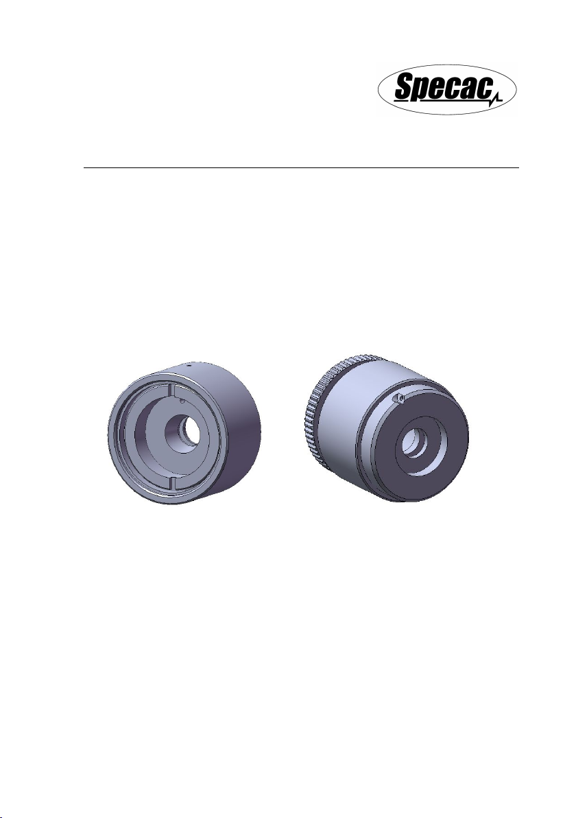
Thermocouple Well Hole Connections
When the Solids Cell Holder P/N GS20600 is to be used in the
Electrical Heating Jacket P/N GS20730, a connection must be made to
the temperature controlling thermocouple assembly of the Electrical
Heating Jacket. The tip of the thermocouple is securely fitted into the
Solids Cell Holder via the thermocouple well hole (9) – see Fig. 3.
Explanation of how to connect the thermocouple is found from the
instruction manual for the Electrical Heating Jacket P/N GS20730.
Similarly, when the Solids Cell Holder P/N GS20610 is to be used in
the Variable Temperature (VT) Cell P/N GS21525, it is possible to
connect an additional “monitoring” thermocouple assembly to the
Solids Cell Holder to measure the temperature of the solid sample
more precisely than the temperature value shown for the VT Cell from
its own temperature controlling thermocouple. The tip of the monitoring
thermocouple is securely fitted into the Solids Cell Holder via the
thermocouple well hole (9) – see Fig. 4. Explanation of how to connect
the monitoring thermocouple is found from the instruction manual for
the VT Cell P/N GS21525.
User Manual
10
4. Legend of Bubble Part Numbers
For Solids Cell Holder P/N GS20600
1) Retaining ring.
2) Body.
3) Pressure plate.
4) Alignment pin.
9) Thermocouple well hole.
For Solids Cell Holder P/N GS20610
5) Location plate.
6) Pressure plate.
7) Inner threaded cell body.
8) Outer threaded cell body.
9) Thermocouple well hole.
Notes for Usage of GS20600 or GS20610
Worldwide Distribution
France
Eurolabo - Paris.
Tel.01 42 08 01 28
Fax 01 42 08 13 65
email: contact@eurolabo.fr
Germany
L.O.T. - Oriel GmbH & Co,
KG - Darmstadt
Tel: 06151 88060
Fax: 06151 880689
email:info@LOT-Oriel.de
Website: www.LOT-Oriel.com/de
Japan
Systems Engineering Inc. -Tokyo
Tel: 03 3946 4993
Fax: 03 3946 4983
email:systems-eng@systems-eng.co.jp
Website: www.systems-eng.co.jp
Spain
Teknokroma S.Coop C. Ltda
Barcelona
Tel: 93 674 8800
Fax: 93 675 2405
email: comercial@teknokroma.es
Switzerland
Portmann InstrumentsAG
Biel-Benken
Tel: 061 726 6555
Fax: 061 726 6550
email: info@portmann-instruments.ch
Website:www.portmann-instruments.ch
USA
SPECAC INC.
414 Commerce Drive
Suite 175,
Fort Washington,
PA 19034, USA
Tel: 215 793 4044
Fax: 215 793 4011
United Kingdom
Specac Ltd. - London
Unit 12, Science & Innovation Centre
Halo Business Park
Orpington
Kent BR5 3FQ
Tel:+44 (0) 1689 873134
Registered No. 1008689 England
Brilliant Spectroscopy™
www.specac.com
SPECAC INC.
414 Commerce Drive
Suite 175,
Fort Washington,
PA 19034, USA
Tel: 215 793 4044
Fax: 215 793 4011
SPECAC LTD.
Unit 12, Science & Innovation Centre
Halo Business Park
Orpington
Kent BR5 3FQ
Tel: +44 (0) 1689 873134
Registered No. 1008689 England

This manual suits for next models

1

Other Specac Laboratory Equipment manuals

Specac Atlas GS15515 User manual

Specac

Specac Atlas GS15515 User manual

Specac Storm 10H User manual

Specac

Specac Storm 10H User manual

Specac Gateway ATR User manual

Specac

Specac Gateway ATR User manual

Specac Atmos User manual

Specac

Specac Atmos User manual

Specac Quest ATR GS10800 Series User manual

Specac

Specac Quest ATR GS10800 Series User manual

Specac Golden Gate GS10500 Series User manual

Specac

Specac Golden Gate GS10500 Series User manual

Specac Selector GS19900 User manual

Specac

Specac Selector GS19900 User manual

Specac Gateway GS11155 User manual

Specac

Specac Gateway GS11155 User manual

Specac APEX QUICK RELEASE DIE User manual

Specac

Specac APEX QUICK RELEASE DIE User manual

Specac GS12000 Series User manual

Specac

Specac GS12000 Series User manual

Specac GS10890 User manual

Specac

Specac GS10890 User manual

Specac Golden Gate GS10640 User manual

Specac

Specac Golden Gate GS10640 User manual

Specac Gateway ATR User manual

Specac

Specac Gateway ATR User manual

Specac Atlas GS15640 User manual

Specac

Specac Atlas GS15640 User manual

Specac ARROW Instruction manual

Specac

Specac ARROW Instruction manual

Specac Quest User manual

Specac

Specac Quest User manual

Specac ATMOS A2.5 User manual

Specac

Specac ATMOS A2.5 User manual

Specac Quest User manual

Specac

Specac Quest User manual

Popular Laboratory Equipment manuals by other brands

Bertin Technologies Cryolys Evolution user manual

Bertin Technologies

Bertin Technologies Cryolys Evolution user manual

IKA C-MAG HS4 operating instructions

IKA

IKA C-MAG HS4 operating instructions

Carestream Dryview 6850 Safety manual

Carestream

Carestream Dryview 6850 Safety manual

CORNING Lambda EliteMax Service manual

CORNING

CORNING Lambda EliteMax Service manual

SCHOTT KL 2500 LCD Instructions for use

SCHOTT

SCHOTT KL 2500 LCD Instructions for use

BEHR DG 2+2 user manual

BEHR

BEHR DG 2+2 user manual

IKA C-MAG HS7 manual

IKA

IKA C-MAG HS7 manual

Metrohm 930 Compact IC Flex Oven/ChS manual

Metrohm

Metrohm 930 Compact IC Flex Oven/ChS manual

Fisher Scientific Isotemp 550 Series instruction manual

Fisher Scientific

Fisher Scientific Isotemp 550 Series instruction manual

Monmouth Scientific CT675 operating & maintenance manual

Monmouth Scientific

Monmouth Scientific CT675 operating & maintenance manual

Tuttnauer EZ9Plus Quick installation guide

Tuttnauer

Tuttnauer EZ9Plus Quick installation guide

Scilogex D-500 User instruction manual

Scilogex

Scilogex D-500 User instruction manual

Hoefer MacroVue UV-25 user manual

Hoefer

Hoefer MacroVue UV-25 user manual

Agilent Technologies BenchCel Microplate Handler quick guide

Agilent Technologies

Agilent Technologies BenchCel Microplate Handler quick guide

Image Engineering iQ-Trigger user manual

Image Engineering

Image Engineering iQ-Trigger user manual

CAMAG Derivatizer instruction manual

CAMAG

CAMAG Derivatizer instruction manual

Fisher Scientific 650 Series instruction manual

Fisher Scientific

Fisher Scientific 650 Series instruction manual

Bioneer Exicycler 96 Installation and calibration guide

Bioneer

Bioneer Exicycler 96 Installation and calibration guide

manuals.online logo
manuals.online logoBrands
  • About & Mission
  • Contact us
  • Privacy Policy
  • Terms and Conditions

Copyright 2025 Manuals.Online. All Rights Reserved.