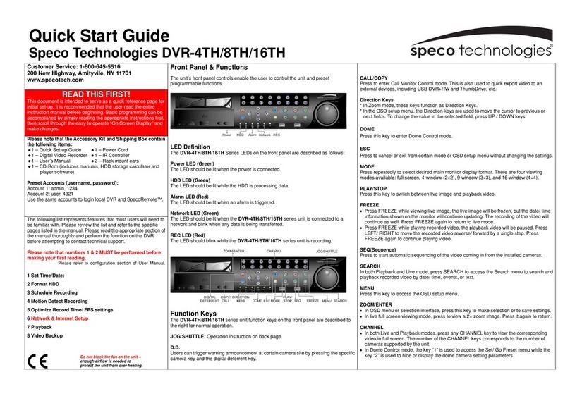
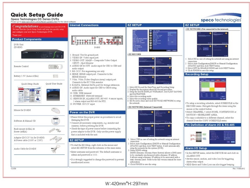
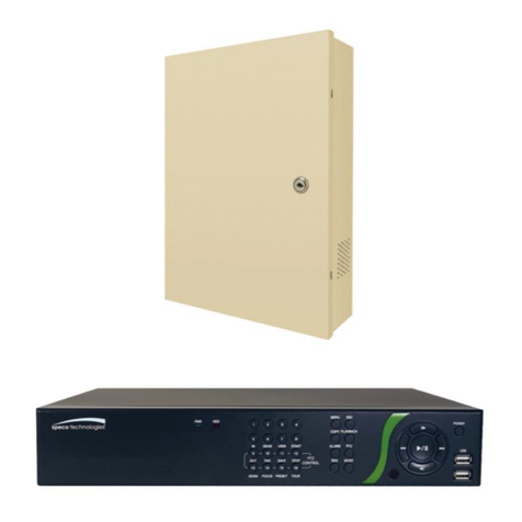
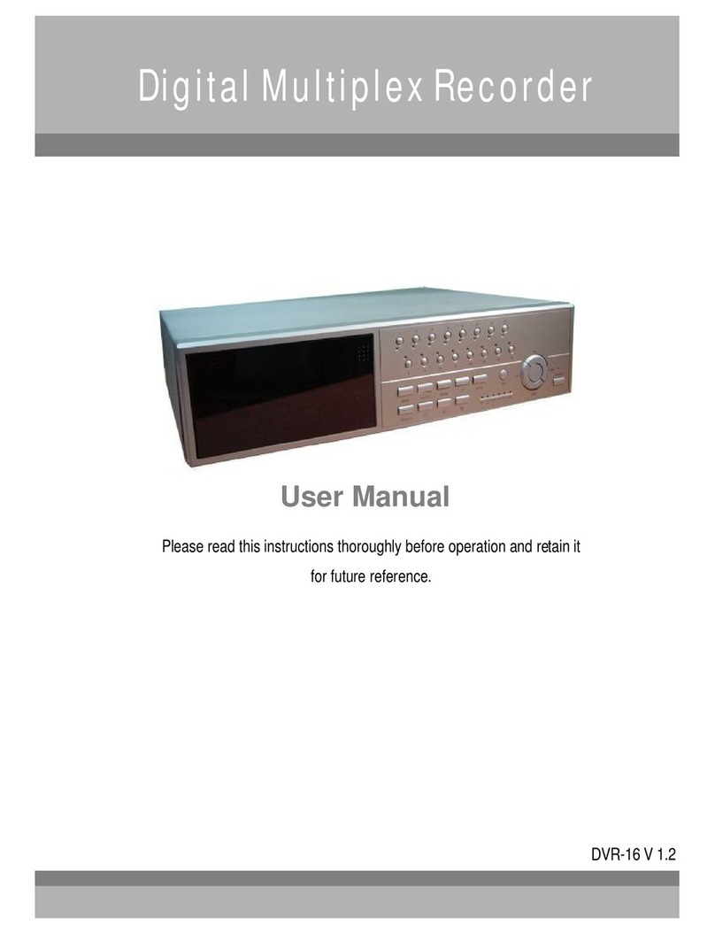
Speco D8WRSM User manual

Product: D8WRSPMQB2 AI- D8WRSPMQB2 Rev a
4/22/14 Page 1 of 20
Speco Technologies Confidential 200 New Highway, Amityville NY 11701
Assembly Instruction
AI – D8WRSMPMQB2
Description: D8WRSM, D16WRSM
Product Code(s): TBD
Equipment #1 Size Phillips head drill, Flat head screwdriver,
Required 3/16” hex head driver, ¼” hex head driver
Associated
Documents:
Eng Approved:
Date:
Alt Approved:
Date:
REVISION HISTORY
DATE INITIAL REASON FOR CHANGE REV.
4/22/14
5/23/14
rm
rm
•
New Document
Changed colors of power cable
NC
a

Product: AI- D8WRSPMQB2 AI- D8WRSPMQB2 Rev a
4/22/14 Page 2 of 20
Speco Technologies Confidential 200 New Highway, Amityville NY 11701
Equipment Required:
10mm open end wrench
10 mm nutdriver
Lamp Cable Assy
Sensor assembly cable
Power cable assy – (see image below)
drill w/ 5/16” drill bit
conical washer
ruler
heat gun
1/8” shrink tubing
Cable Assemblies Required
Refer to Photo 1 on the following page. Mask the case and mark the drill
locations. The holes will be drilled on the door hinge side of the wall mount
and at the specific locations
5.25” and 6.00” from the base.
Use a starter drill such as 1/8”. Final drill size for both holes is 5/16”.

Product: D8WRSPMQB2 AI- D8WRSPMQB2 Rev a
4/22/14
Page 3 of 20
Speco Technologies Confidential 200 New Highway, Amityville NY 11701
Drill Locations Adding the hardware
Connect the Lamp assembly and the sensor switch assembly to the
chassis with the supplied hardware. Note that the switch assembly gets the
conical washer as shown. Below are the 2 cable assemblies mounted to
the chassis (inside).

Product: D8WRSPMQB2 AI- D8WRSPMQB2 Rev a
4/22/14
Page 4 of 20
Speco Technologies Confidential 200 New Highway, Amityville NY 11701
Slide a 1/8” pre-cut shrink tubing over the red wire of the Power Cable.
Solder this wire to the gold terminal post on the Lamp Cable led. Heat the
shrink tubing with the heat gun.
Add a cable anchor to the inside chassis as shown.
Photo right, tie assemblies cable in a neat bundle and secure with a tywrap.
Embossed +

Product: D8WRSPMQB2 AI- D8WRSPMQB2 Rev a
4/22/14
Page 5 of 20
Speco Technologies Confidential 200 New Highway, Amityville NY 11701
The photo above shows the 2 cable assemblies in a bundle.

Product: D8WRSPMQB2 AI- D8WRSPMQB2 Rev a
4/22/14
Page 6 of 20
Speco Technologies Confidential 200 New Highway, Amityville NY 11701
2.0 - Pre Assembly
1) Attach brackets to the HDD using four DVRWM632SCREW (No ring permitted on screw)
2) Attach the control board to the painted side of WRSMPlate using two 2-56 screws
(90272A081), two 2-56 nuts (90480A003) and two bumpers (9540K11). Place the bumper
between the board and the plate. The nut should be on the plate. The wired side should be
at the bottom of the plate near the tabs.
Repeat on other side.

Product: D8WRSPMQB2 AI- D8WRSPMQB2 Rev a
4/22/14
Page 7 of 20
Speco Technologies Confidential 200 New Highway, Amityville NY 11701
3) Attach the Monitor board to the unpainted side of the WRSMPlate using two 2-56 screws
(90272A081), two 2-56 nuts (90480A003) and two bumpers (9540K11). Place the bumper
between the board and the plate as shown below. The nut should be on the board.
4) Connect the power board cable and the video cable to the monitor board
5) Release the ribbon from the back of the monitor and place the power connector through the
hole in the WRSMPlate.

Product: D8WRSPMQB2 AI- D8WRSPMQB2 Rev a
4/22/14
Page 8 of 20
Speco Technologies Confidential 200 New Highway, Amityville NY 11701
6) Slide the monitor into the tabs and lock down using the clip. Attach the clip with a 4-40
screw (90272A106) and a 4-40 locknut (90633A05).
7) For the new WRSMPLATE, add small piece of doubled sided tape to lower part of the
monitor side and below one clip.
8) Connect the monitor power connector to the monitor board
9) Attach the ribbon to the monitor board by releasing the clip and inserting the ribbon. Be
sure not to crease the ribbon. Once inserted lock in by pressing the clips back in.

Product: D8WRSPMQB2 AI- D8WRSPMQB2 Rev a
4/22/14
Page 9 of 20
Speco Technologies Confidential 200 New Highway, Amityville NY 11701
10) Group the cables and wire tie down using the open hole on the monitor board as shown
below.

Product: D8WRSPMQB2 AI- D8WRSPMQB2 Rev a
4/22/14
Page 10 of 20
Speco Technologies Confidential 200 New Highway, Amityville NY 11701
Section 3.0 - Main Assembly
Box Breakdown:
1) Place the WM Housing in front of you and tighten the nylon screw (93135A144) into the 3
pems which will not be utilized during the build. See below.
HDD
Monitor
Main Board
IR Board

Product: D8WRSPMQB2 AI- D8WRSPMQB2 Rev a
4/22/14
Page 11 of 20
Speco Technologies Confidential 200 New Highway, Amityville NY 11701
2) Place a 1” Hex Standoff (93620A446) with spacer nut (90760A007) in the bottom left pem
as shown below.
3) Lay the main board on the pem so they align with connectors facing the holes and lock
down the corner with IR Board using the 1” Hex Standoff (93620A446), this must be done
by hand tool.
Spacer Nut

Product: D8WRSPMQB2 AI- D8WRSPMQB2 Rev a
4/22/14
Page 12 of 20
Speco Technologies Confidential 200 New Highway, Amityville NY 11701
4) Attach the main board to the housing pems using 6-32 1.5” standoffs (93620A448) in each
of the 3 locations shown below.
5) Obtain the IR Board, connect one end of the cable to the back of the IR board. Attach the
IR Board to the standoff using a 6-32 screw (DVRWM632SCREW) and a 6-32 standoff 7/16”
(93620A730) as shown below.

Product: D8WRSPMQB2 AI- D8WRSPMQB2 Rev a
4/22/14
Page 13 of 20
Speco Technologies Confidential 200 New Highway, Amityville NY 11701
6) Attach the other end of the IR Board cable to the main board.
7) Place the HDD in place on the four pems and lock in using a 6-32 metal screw in each pem.
Orient the HDD so that the connectors are facing toward the IR Board. Position the HDD so
that it DOES NOT cover the brace hole in the top left corner of the housing.
8) Connect the SATA Combo connector to the HDD and the main board, then using a wire tie
secure the wires. The IR Board cable does not get bundled.
HDD must be positioned as far to
the right as possible.
HDD Connectors
Pems for HDD
(same on other side)
7/16” Standoff

Product: D8WRSPMQB2 AI- D8WRSPMQB2 Rev a
4/22/14
Page 14 of 20
Speco Technologies Confidential 200 New Highway, Amityville NY 11701
9) Route the Splitter as shown below. Connect the YDCSplitter to the monitor and to the DVR.
10) Zip tie the balance of the splitter so it is neat.
11) The unit is now ready for the monitor plate to be mounted. Move the Monitor sub assembly
onto the unit.
12) Attach the Video connector from the monitor board to the RCA to BNC connector and attach
to the BNC Video output on the DVR. Zip tie the cable so it runs cleanly back up the
connector toward the monitor.
Sata Combo
Connector
SATA DATA
SATA
Power
Zip Tie
Splitter Input Monitor
Splitter End
DVR Splitter End

Product: D8WRSPMQB2 AI- D8WRSPMQB2 Rev a
4/22/14
Page 15 of 20
Speco Technologies Confidential 200 New Highway, Amityville NY 11701
13) Wrap the power cable around the bottom left pem and lock the plate down using four 6-32
screws (90272A106).
When the main board is installed, connect the Sensor Cable (twisted pair)
to the 4
th
column on the terminal block. There is no polarity for this
connection.
Connect the 2 remaining black wires to the 6
th
column as shown. There is
no polarity for this connection.
RCA2BNC
Connector

Product: D8WRSPMQB2 AI- D8WRSPMQB2 Rev a
4/22/14
Page 16 of 20
Speco Technologies Confidential 200 New Highway, Amityville NY 11701
Assembly complete
Upgrade this unit with the following firmware:
main_d8wrspb_speco_3.8.2_20131101.bin
Connect Power connector as
shown

Product: D8WRSPMQB2 AI- D8WRSPMQB2 Rev a
4/22/14
Page 17 of 20
Speco Technologies Confidential 200 New Highway, Amityville NY 11701
Software Test:
After the upgrade, connect a camera to Ch 1 input and allow the unit to
record for at least 1 minute.
Install a formatted thumb drive in a USB terminal.
Next: Press the red button that was installed and hold for 3 seconds or until
the LED illuminates.
An icon will appear on the screen.

Product: D8WRSPMQB2 AI- D8WRSPMQB2 Rev a
4/22/14
Page 18 of 20
Speco Technologies Confidential 200 New Highway, Amityville NY 11701
The unit will beep 3 times when the download is complete.
Click on the icon and and close the window.
Verify the download with the thumbdrive installed on a PC or laptop by
opening the DVR player and selecting the Ch1 file in the DVR folder.

Product: D8WRSPMQB2 AI- D8WRSPMQB2 Rev a
4/22/14
Page 19 of 20
Speco Technologies Confidential 200 New Highway, Amityville NY 11701
Section 4.0 - Prepare for Burn-In and post Burn-In Instructions
1) Connect Door to housing and position WM for testing and Burn-in.
2) Post Burn-in attach:
1. The plastic caps to the bottom openings
2. Lock to the housing door.
3. Sticker on the Door and Label of the unit.
4. Place the unit in a clear plastic bag prior to packaging.
Finished Product:

Product: D8WRSPMQB2 AI- D8WRSPMQB2 Rev a
4/22/14
Page 20 of 20
Speco Technologies Confidential 200 New Highway, Amityville NY 11701
Section 5.0 - QA Checklist
Quality Assurance will inspect for the following:
1) Main Board:
•Number of channels on Main Board matches Work Order.
•The Main board is secured to the housing; all screws are present and tight.
•Nylon screws are present below the main board and in any exposed pem.
2) IR Board:
•IR Board is properly mounted with two metal screws.
•Standoffs are present below the IR Board.
3) HDD:
•HDD size matches Work Order.
•All 8 screws on HDD (4) and bracket (4) are tightened.
•HDD is securely installed, no movement when a force is applied.
•HDD does not block knockout
4) Monitor Plate
•Monitor is properly secured to plate and plate is properly secured to housing.
•Video connector is fully engaged and cables are neatly wrapped to it.
5) Connectors and cables:
•SATA Combo Connectors are connected to the HDD and Main Board.
•IR Board connector is seated to IR Board and Main Board.
•Ribbon Connector properly connected to monitor and monitor board.
•Wire tie is present and bundles cables together, not including IR cable.
•Power splitter is properly connected.
This manual suits for next models
1
Table of contents
Other Speco DVR manuals

Speco
Speco DVR-4TN Series User manual

Speco
Speco VT Instruction manual
Speco
Speco D16HS User manual

Speco
Speco H24HRN User manual

Speco
Speco D16DS User manual

Speco
Speco D24GS Technical manual

Speco
Speco D8HS Instruction manual

Speco
Speco N64NR48TB User manual

Speco
Speco EZVR8 User manual

Speco
Speco CS Series User manual

Speco
Speco EZVR8 User manual

Speco
Speco DVR-16TS/750 User manual

Speco
Speco DxVT Series User manual

Speco
Speco D4CX Technical manual

Speco
Speco D8HS2TB User manual

Speco
Speco N64NR User manual

Speco
Speco DVR-PC8 Series User manual
Speco
Speco EZVR4 User manual

Speco
Speco HRLN User manual

Speco
Speco D8HS User manual