SPIERINGS AT5 User manual

MANUAL SPIERINGS TRUCK AT5
AT5-UK-030626 01-12-09 I
Introduction
This manual is put together to provide the user of the Spierings truck, model AT5, with information about this
truck's construction, operation and maintenance.
The driver must have a driving license for driving a heavy truck and have sufficient technical knowledge.
The AT5 truck is built to serve as carriage for the Spierings folding crane, model SK598. For operation, technical
data and maintenance of this folding crane we refer to the subjoined manual.
Because the AT5 is provided with five axles, of which 3 axles are steered, excellent mobility is guaranteed on the
work site as well as on the road. The axles are hydro-pneumatically suspended, whereas the height can be
adjusted and/or blocked. Three axles are driven by a 12.6 litres DAF diesel engine and a gearbox with sixteen
gears forward and two gears reverse. After the gearbox is a high/low gear shift (transfer case), which has two
different gears and a neutral. A gear for driving on the road and a gear for driving off the road. Neutral serves for
the generator drive by the high/low gear shift PTO.
Furthermore, there is a hydraulic system for operating the crane's outrigger system and, when the crane is not
equipped with a separate engine on the upper frame, the truck has a 400 Volt generator to provide the crane with
the necessary power.
The following items are dealt with in this manual.
General data. In this chapter you will find a description of the measurements and technical specifications.
Location and explanation of controls.
Operating the AT5. This chapter gives you instructions for optimal use of the truck.
Maintenance of the AT5, maintenance schedules as well as explanation of the maintenance work to be
carried out. You will also find a maintenance plan containing the specification of the used parts and
lubricants.
Specification of drive line and steering system parts
Explanation of the hydraulic, pneumatic and electrical system.
You will find the outline drawings and diagrams referred to at the back of this manual in the enclosures.
Due to the continuous product development at Spierings Kranen the descriptions and pictures may not be all together similar to the condition on your vehicle.
Copyright 2003. No part of this publication may be reproduced or published, in any form or in any way, by print, photo print, microfilm or any other means without prior
permission from the manufacturer.

MANUAL SPIERINGS TRUCK AT5
AT5-UK-030626 01-12-09 II
Table of contents
Introduction..........................................................................................................................................I
Table of contents................................................................................................................................II
1. General data AT5.....................................................................................................................1-1
2. Operation..................................................................................................................................2-1
2.1. Get to know the truck.....................................................................................................2-1
2.2. Truck cab.......................................................................................................................2-4
2.3. Control Panel.................................................................................................................2-7
2.4. Driving the Spierings crane..........................................................................................2-16
2.4.1. Starting ..........................................................................................................2-16
2.4.2. Driving off.......................................................................................................2-17
2.4.3. Change gear..................................................................................................2-17
2.4.4. Stopping.........................................................................................................2-18
2.4.5. Turning off the engine....................................................................................2-18
2.5. Driving off the road.......................................................................................................2-18
2.5.1. Off the road gear shift High/Low transfer case...............................................2-18
2.5.2. Longitudinal differential lock...........................................................................2-19
2.5.3. Transverse differential lock............................................................................2-19
2.5.4. Hydraulic driven axle 1...................................................................................2-19
2.6. Braking system ............................................................................................................2-20
2.6.1. Operating brake.............................................................................................2-20
2.6.2. Parking brake.................................................................................................2-20
2.6.3. Vacuum brake/engine stop............................................................................2-20
2.6.4. Slowing down using the retarder (optional)....................................................2-20
2.7. Parking.........................................................................................................................2-21
2.8. Driving with a trailer .....................................................................................................2-21
2.9. Towing the crane .........................................................................................................2-22
2.9.1. Tow free.........................................................................................................2-22
2.9.2. Towing...........................................................................................................2-22
2.10. Independent rear axle steering ....................................................................................2-23
2.11. Driving with erected tower............................................................................................2-24
2.12. Axle height adjustment.................................................................................................2-25
3. Maintenance.............................................................................................................................3-1
3.1. General..........................................................................................................................3-1
3.2. Safety.............................................................................................................................3-1
3.2.1. Engine..............................................................................................................3-1
3.2.2. Moving components.........................................................................................3-1
3.2.3. Oils and coolant...............................................................................................3-1
3.2.4. Welding............................................................................................................3-1
3.2.5. Environment.....................................................................................................3-2
3.2.6. Cleaning of components..................................................................................3-2
3.3. Maintenance plan truck AT5 ..........................................................................................3-3
4. Periodic checks .......................................................................................................................4-1
4.1. Daily checks...................................................................................................................4-1
4.1.1. Check engine oil level......................................................................................4-1
4.1.2. Check coolant level..........................................................................................4-1
4.1.3. Tyres and rims.................................................................................................4-2
4.1.4. Lighting and controls........................................................................................4-2

MANUAL SPIERINGS TRUCK AT5
AT5-UK-030626 01-12-09 III
4.2. Weekly checks...............................................................................................................4-2
4.2.1. Check for leaks (oil, air, coolant)......................................................................4-2
4.2.2. Windscreen washer fluid level .........................................................................4-2
4.2.3. Clutch fluid level...............................................................................................4-2
4.2.4. Draining air vessels .........................................................................................4-3
4.2.5. Draining and bleeding fuel system water separator.........................................4-3
5. Lubrication...............................................................................................................................5-1
5.1. Central lubricating system..............................................................................................5-1
5.2. Manual lubrication..........................................................................................................5-3
5.2.1. Outrigger-cylinders ..........................................................................................5-3
5.2.2. Gear change mechanism.................................................................................5-3
5.2.3. Driven axles.....................................................................................................5-3
5.2.4. Cardan shafts ..................................................................................................5-4
5.2.5. Steering system...............................................................................................5-5
6. The drive system.....................................................................................................................6-1
6.1. The diesel engine ..........................................................................................................6-2
6.1.1. Specification diesel engine ..............................................................................6-2
6.2. Maintenance plan diesel engine ....................................................................................6-2
6.2.1. Maintenance activities First service interval.....................................................6-2
6.2.2. Maintenance activities X service interval .........................................................6-3
6.2.3. Maintenance activities Y service interval .........................................................6-3
6.3. Carrying out maintenance work diesel engine ...............................................................6-3
6.3.1. Change engine oil............................................................................................6-3
6.3.2. Oil Filter Replacement .....................................................................................6-3
6.3.3. Air cleaner cleaning/replacement.....................................................................6-4
6.3.4. Fuel filter replacement .....................................................................................6-4
6.3.5. Change filter element water separator.............................................................6-5
6.3.6. Changing coolant.............................................................................................6-5
6.4. Inspections.....................................................................................................................6-6
6.4.1. Check for fuel leaks.........................................................................................6-6
6.4.2. Check components and hose connections for leaks........................................6-6
6.4.3. Radiator and intercooler element inspection/cleaning .....................................6-6
6.4.4. Cooling system hoses and air inlet system inspection.....................................6-6
6.4.5. Check outlet system for connection and leaks.................................................6-6
6.4.6. Check coolant antifreeze concentration...........................................................6-7
6.5. The clutch and gearbox .................................................................................................6-7
6.5.1. Specification gearbox ......................................................................................6-7
6.5.2. Fluid torque converter......................................................................................6-7
6.5.3. Bridging clutch.................................................................................................6-8
6.5.4. Freewheel clutch..............................................................................................6-8
6.5.5. Retarder...........................................................................................................6-9
6.5.6. Clutch ..............................................................................................................6-9
6.6. Carrying out maintenance work gearbox and clutch......................................................6-9
6.6.1. Bleeding Gearbox............................................................................................6-9
6.6.2. Drain oil gearbox............................................................................................6-10
6.6.3. Filling gearbox and converter with oil.............................................................6-10
6.6.4. Change / clean oil filter ..................................................................................6-10
6.6.5. Take off and replace the suction filter............................................................6-11
6.6.6. Clutch bleeding..............................................................................................6-11
6.6.7. Check clutch..................................................................................................6-11
6.7. The transfer case.........................................................................................................6-12
6.7.1. Specification transfer case.............................................................................6-12
6.8. Carrying out maintenance work transfer case..............................................................6-12
6.8.1. Bleeding.........................................................................................................6-12
6.8.2. Check oil level................................................................................................6-12

MANUAL SPIERINGS TRUCK AT5
AT5-UK-030626 01-12-09 IV
6.8.3. Change oil in transfer case............................................................................6-12
6.9. Axles/brakes................................................................................................................6-13
6.9.1. Specification axles/brakes .............................................................................6-13
6.10. Carrying out maintenance work axles/brakes ..............................................................6-13
6.10.1. Checking oil level differential housings and hubs ..........................................6-13
6.10.2. Change oil......................................................................................................6-13
6.10.3. Check the brake lining thickness ...................................................................6-14
6.10.4. Brake test.......................................................................................................6-14
7. The hydraulic system..............................................................................................................7-1
7.1. Structure hydraulic system.............................................................................................7-1
7.1.1. Hydraulic pump system....................................................................................7-1
7.1.2. Hydraulic steering system................................................................................7-2
7.1.3. Hydraulic suspension.......................................................................................7-3
7.1.4. Hydraulic outrigger system ..............................................................................7-3
7.1.5. Hydraulic drive axle 1 (option) .........................................................................7-3
7.2. Maintenance Hydraulic System .....................................................................................7-3
7.2.1. Check oil level..................................................................................................7-4
7.2.2. Change hydraulic oil ........................................................................................7-4
7.2.3. Change oil filter................................................................................................7-4
7.2.4. Fine filter replacement .....................................................................................7-4
7.2.5. Check accumulators ........................................................................................7-4
7.2.6. Check hydraulic hoses and connections..........................................................7-4
8. The Steering System...............................................................................................................8-1
8.1. Maintenance Steering System.......................................................................................8-1
8.1.1. Align.................................................................................................................8-1
8.1.2. Check steering arms and ball joints for play ....................................................8-1
9. The Pneumatic System ...........................................................................................................9-1
9.1. Structure Pneumatic System .........................................................................................9-1
9.1.1. Braking System................................................................................................9-1
9.1.2. Accessories .....................................................................................................9-1
9.2. Maintenance Pneumatic System....................................................................................9-2
9.2.1. Change filter element air-dryer ........................................................................9-2
9.2.2. Check air vessels.............................................................................................9-2
9.2.3. Check the air lubricator / water separator........................................................9-2
9.2.4. Check brake pressure......................................................................................9-2
10. Electrical System...................................................................................................................10-1
10.1. Structure Electrical System..........................................................................................10-1
10.1.1. Power for powering the crane........................................................................10-1
10.1.2. Fuses.............................................................................................................10-1
10.1.3. Lighting..........................................................................................................10-2
10.2. Maintenance Electrical System....................................................................................10-3
10.2.1. Charging batteries .........................................................................................10-3
10.2.2. Batteries Replacement...................................................................................10-3
11. Technical Data.......................................................................................................................11-1
12. Enclosures.............................................................................................................................12-1

MANUAL SPIERINGS TRUCK AT5
AT5-UK-030626 01-12-09 1-1
1. General data AT5
The AT5 carriage is especially designed for the Spierings SK598 folding crane. Extra attention is paid to a smooth
and comfortable transport to the work site. The crane is suited for driving on public roads, fully equipped with
counterweight and tools. The chassis is an especially rigid structure to create a good crane support.
In Picture 1-1 you will find the measurements of the SK598 with the AT5 carriage. The dimensions given are the
overall dimensions, axle bases and turning circle.
Picture 1-1
Drive unit:
12.6 litres DAF diesel engine with turbo compressor and intercooler (type XF 315 M).
ZF gearbox with fluid torque converter and retarder; 16 gears forward and two gears reverse.
STEYR high/low gear shift, transfer case, with high speed (road) and low speed (off the road) transmission.
Five Ginaf axles, where axles two, three and five are driven.
Electronic accelerator "E-gas” with speed control.
Built-in generator for powering the crane.
Steering:
Axles 1, 2, 4 and 5 are steered.
Mechanically coupled steering, where axle four and five are steered in the opposite direction of axle one and
two, realizing a small turning circle.

MANUAL SPIERINGS TRUCK AT5
AT5-UK-030626 01-12-09 1-2
Axle four and five can be uncoupled mechanically. Independent rear axle steering is now possible using a
small joystick. Lift axle three to use this option.
Hydraulic powered steering system.
Fitted with an emergency steering pump, so when the main steering pump or diesel engine malfunctions, the
truck remains steerable until it is at a standstill.
Provisions for driving off the road:
-axle height adjustable
-high/low gear shift transfer case can be put in low gear for driving off the road
-longitudinal and transverse differentials can be locked
Suspension:
Hydro-pneumatic suspension
The suspension can be blocked (e.g. when driving with erected tower).
Braking system:
Pneumatic brakes with anti-blocking system (ABS).
4-point outrigger system:
Wide support base : 7.2 m x 7.2 m
Narrow support base : 7.2 m x 5,65 m
Power supply:
When there is no separate diesel engine on the upper frame, the upper frame can be supplied with power in two
different ways:
External power-supply 40 kVA during rigging up/rigging down, 40 kVA during operation
The truck built-in Leroy Somer 70 kVA generator for power supply to the upper frame when (sufficient)
external power is lacking.
Further data:
Maximum speed limited to 85 km/h
Minimum speed at 1250 rpm: 1.9 km/h (is 32 m/min)
Truck weight including upper frame 60,000 kg
The axle load is 12,000 kg per axle
MANUAL SPIERINGS TRUCK AT5
AT5-UK-030626 01-12-09 1-3
Identification:
Engine number: left-hand side on the engine block above the fuel pump.
Carriage frame number: on the identification plate in the co-driver's leg-room (See Picture 1-2) and
stamped in the right frame girder in front of the first axle (See Picture 1-3).
Picture 1-2
Picture 1-3


MANUAL SPIERINGS TRUCK AT5
AT5-UK-030626 01-12-09 2-1
2. Operation
2.1. Get to know the truck
Picture 2-1
MANUAL SPIERINGS TRUCK AT5
AT5-UK-030626 01-12-09 2-2
1a. Truck cab
Besides driving the crane, with the controls in the truck cab you can support the crane on outriggers, adjust the
carriage axle height and switch the generator on and off.
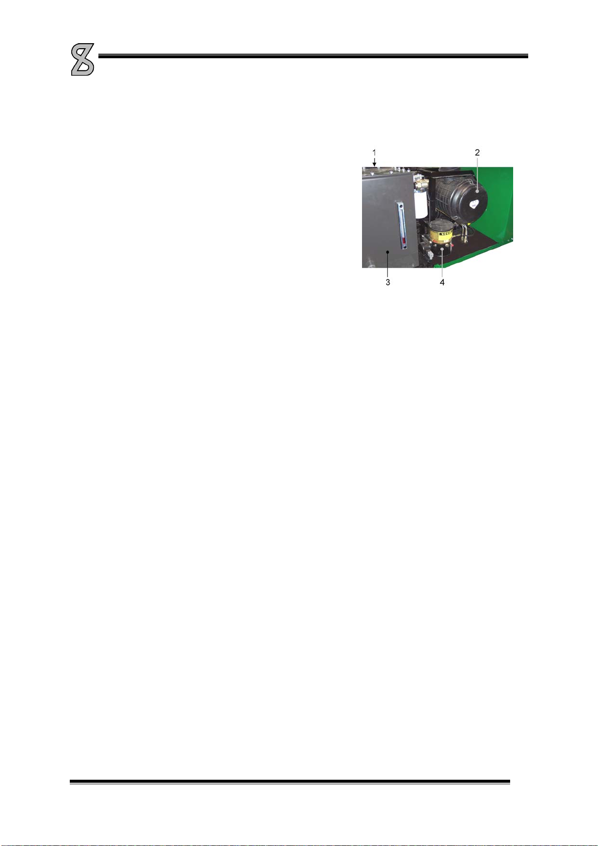
2a. Hydraulic oil tank / battery box
On this side of the truck, under the engine cowling, you will find the
hydraulic oil tank (See Picture 2-2, nr.3) and air cleaner (nr.2).
Behind the oil tank, you’ll find the battery-box (nr.1).
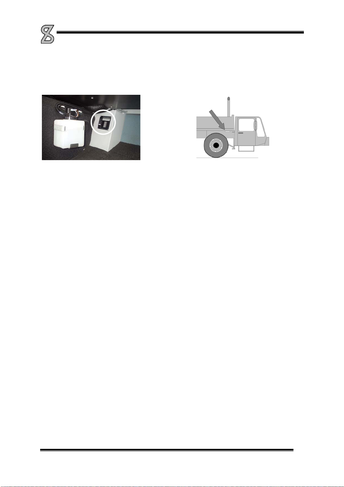
2. Battery switch
On the left side behind the cab, you’ll find the battery switch.
Picture 2-2
3. Toolbox at the rear / power box
You will find the power-box in this storage box by opening the right sliding door.
With the selector switch on the power-box, the power supply for the crane is selected. Either an external power
supply can be connected to this power box, or the built-in generator supplies the power. Power can also be
branched off for accessory equipment.
4. Steel support plates
To obtain a solid support base on a week ground, support plates have to be used. In this place, 4 steel support
plates are stored.
5. Storage room support plates
Under the truck cab, there are 2 storages with 2 synthetic support plates each (or 3 each in combination with steel
support frames).
These synthetic support plates have to be used to rig up the crane on narrow support base, after which the steel
support plates can be placed, using the crane. After placing the steel support plates you can outrigger to wide
support base.
6. Outriggers
At both sides of the truck there are 2 extending outrigger beams, and to each beam a hydraulically operated
outrigger (See Picture 2-3). These outriggers provide stability during hoisting operation. The outrigger beams
have an antiskid coating to prevent skidding. The outrigger pad holders can be used to facilitate stepping on the
outrigger beam.
With a separate (remote) control box the outriggers can be radio controlled. On the rear outrigger beams are
levels to check if the crane set-up is level.

MANUAL SPIERINGS TRUCK AT5
AT5-UK-030626 01-12-09 2-3
Picture 2-3
7. Fuel tank
The fuel tank capacity is 600 litres.
8. Bumper
The crane has a standard bumper at the rear. When the bumper is folded up, the towing hook can be used (refer
“Driving with a trailer”).
9. Jib turning pipe
Through a hole in the deck you can reach the jib turning pipe. This pipe is used to swing the jib in front of the
tower during assembly and back when dismantling the crane.
10. Work lamps
To the rear of the cab and truck are mounted work lamps, which can be
switched on/off from the cab.
By unscrewing the knob, the lamp support can be moved to the left and right
(See Picture 2-4).
Picture 2-4
11. Truck ladders
To facilitate getting on the truck three ladders are mounted. Two ladders
are mounted between axle 2 and 3. To pull you up, brackets are mounted
on the deck.
The third ladder is mounted on the deck on the side of the electrical
cabinet of the crane. Pick up the free end of the ladder so the pin comes
out of the deck (See Picture 2-5) and swing the ladder outside the frame.
When swinging back the ladder, make sure the pin returns in the hole.
Picture 2-5

MANUAL SPIERINGS TRUCK AT5
AT5-UK-030626 01-12-09 2-4
12. Central lubricating system
This is the grease reservoir for the truck's central lubricating system.
13. Concrete bucket / brick gripper support (optional)
On the bumper a support can be mounted to carry a concrete bucket or a brick gripper.
14. Rear-/side view cameras (optional)
To broaden your view at the rear and right-hand side of the truck cameras can be installed. In the cab a monitor is
installed, showing the camera view.
Standard, the view of the side camera is shown. When putting the transmission in reverse, the monitor
automatically switches over to rear camera view.
2.2. Truck cab
In the truck cab you drive the crane safely and comfortably to its destination. This chapter makes you familiar with
the cab.
Getting in
Use the step under the door. Make use of the steering wheel to hold on to.
Doors
Turn the handle up to open the door from the inside. The door can only be locked up from the outside. There is an
ashtray on the inside of the door. After opening the ashtray, you push the locking device down to remove the
ashtray from the holder to empty it.
Wing mirrors
The wing mirrors may be adjusted by hand. Make sure the mirrors are adjusted before driving off, so that you
have satisfactory view. The mirror heating can be switched on with the switch on the control panel. (No. 10)
MANUAL SPIERINGS TRUCK AT5
AT5-UK-030626 01-12-09 2-5
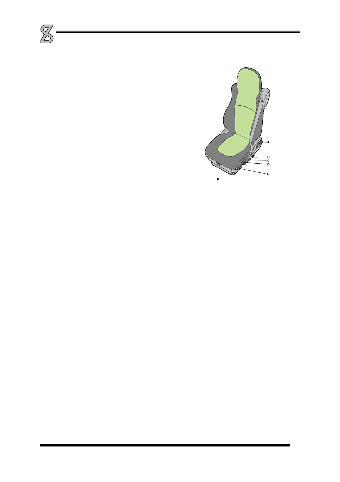
Seats
The cab has room for the driver and a co-driver. Only the driver's
seat has pneumatic suspension. The seats' position can be adjusted.
This should only be done when the vehicle stands still.
A) Back adjustment
B) Lumbar support adjustment (push = pumping up and pull =
deflating)
C) Height adjustment (pulling the handle = up and pushing it =
down)
D) Tipping the seat
E) Handle fast lowering
F) Adjustment seat
Picture 2-6
Safety belts
The seats are fitted with safety belts. Driver and co-driver must wear them when driving. Do not modify the belt or
its attachment by yourself. Regularly check its operation by jerking the belt from its winding mechanism. The belt
must lock when doing this. Have the locking device repaired or replaced when it does not function properly. When
the belt was heavily loaded during a collision, it must be completely replaced, even if it looks like there is nothing
wrong with it.
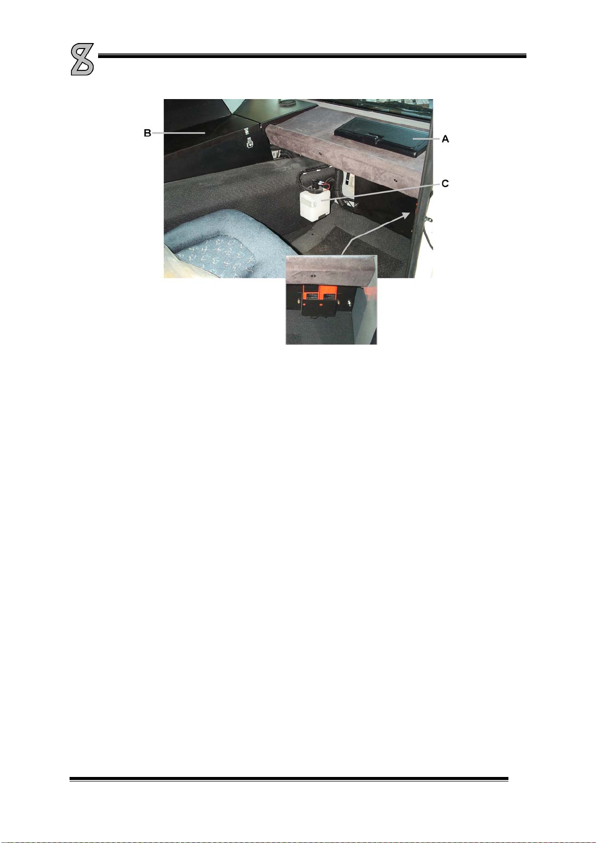
Storage room
In the middle of the cab ceiling is a storage compartment. It has a lockable lid at the driver's side and at the side
of the co-driver. There is another storage compartment at the co-driver's side in the dashboard (See Picture 2-7,
A).
Sun blind
To prevent sunlight from blinding you, a sun blind is mounted above the windscreen for the driver and the co-
driver. Pull down the blind with the joggle in the middle of the blind. The blind will remain in the desired position.
Push the button on the side of the blind to roll it up.
Fuse box
The fuse box is at the co-driver's side in the centre console (See Picture 2-7, B). You will find the fuses listed in
the enclosures.
Windscreen washer reservoir (See Picture 2-7, C)
Central lubricating system (optional)
The central lubricating system controls are on the centre panel at the co-driver's side. It can be opened by means
of 2 clamps (See Picture 2-7, B).
MANUAL SPIERINGS TRUCK AT5
AT5-UK-030626 01-12-09 2-6
Picture 2-7
Battery charger remote control batteries
You will find the battery charger for the remote controls on the left under the dashboard at the driver's side (See
Picture 2-7).
Every remote control comes with 2 batteries each.
While the batteries are charged, the indicator lamp lights. As soon as they are fully charged, the lamp starts
flashing.
Fire extinguisher
One fire extinguisher is behind the co-driver's seat.
On the right behind the control box in the crane cab is the second fire extinguisher.
The fire extinguishers must be inspected every year by the authorities.
MANUAL SPIERINGS TRUCK AT5
AT5-UK-030626 01-12-09 2-7
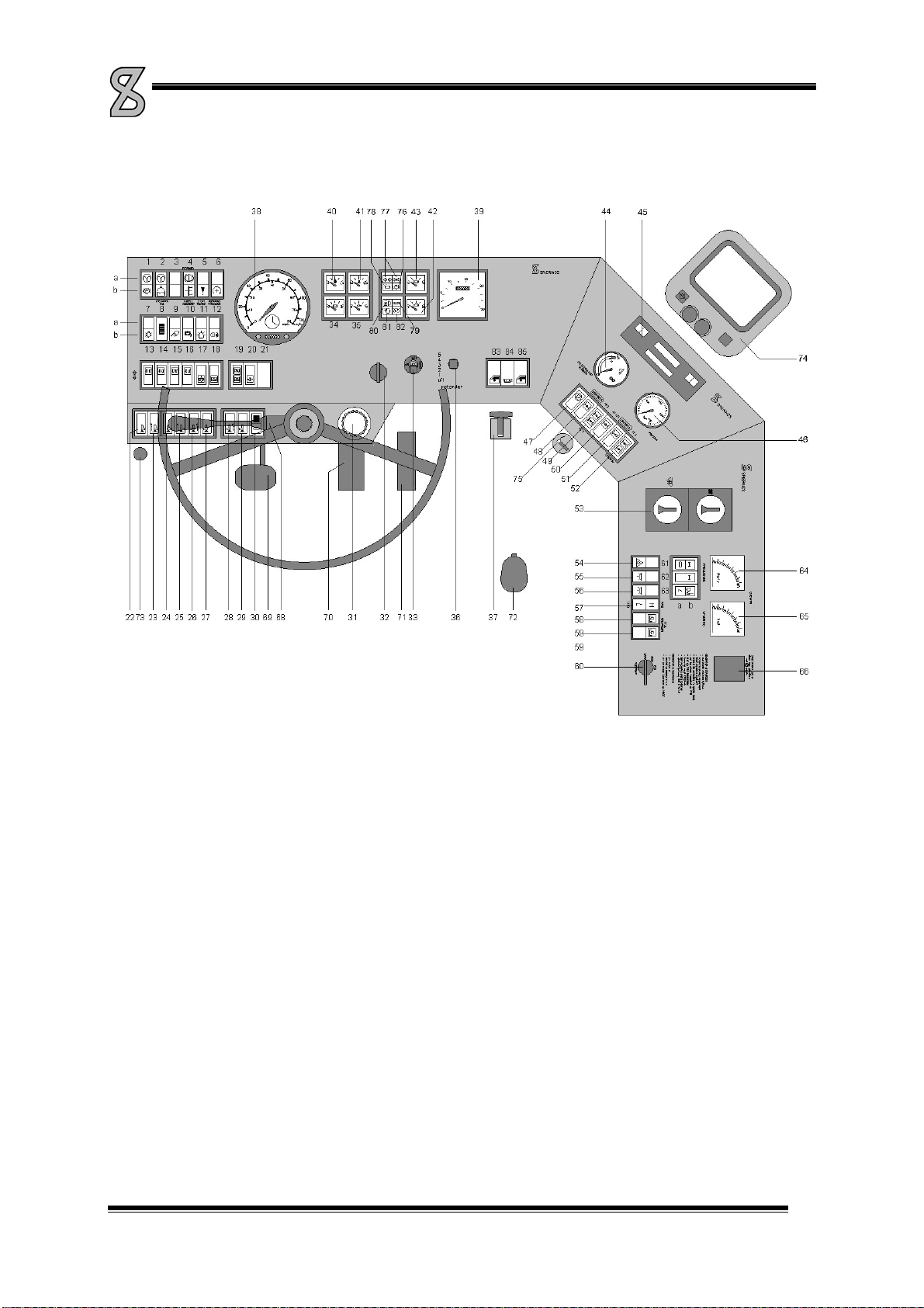
2.3. Control Panel
1a Indicator lamp steering pressure circuit
1b Indicator lamp parking brake
2a Indicator lamp steering pressure circuit 2
2b Indicator lamp coolant level
3 Not in use
4a Indicator lamp retarder on
4b Indicator lamp fluid torque converter on
5a E-gas malfunction diagnosis switch
6 Switch increase rpm
7 Light switch, off/parking light/dipped beam
8 Dimmer dashboard lighting
9 Switch work lamps
10 Switch mirror heating
11 Switch rota flares
12 Switch fog tail-light
13 Switch alls axles up/down
14 Switch axles 1 and 2 up/down
15 Switch axle 3, 4 and 5 left-hand side up/down
16 Switch axle 3, 4 and 5 right-hand side
up/down
17 Switch/indicator lamp levelling
18 Switch driving/blocking
19a Indicator lamp off the road mode
19b Indicator lamp blocking
20 Indicator lamp max. pressure outrigger-
/suspension system
21 Not in use
22 Switch outrigger beam front left-hand side
retract/extend
23 Switch outrigger front left-hand side
retract/extend
24 Switch outrigger beam rear left-hand side
retract/extend
25 Switch outrigger rear left-hand side
retract/extend
26 Switch outrigger front right-hand side
retract/extend
27 Switch outrigger beam front right-hand side
retract/extend
28 Switch outrigger rear right-hand side
retract/extend
29 Switch outrigger beam rear right-hand side
retract/extend
30 Switch outrigger controls on/off
31 Reservoir clutch fluid
32 Ignition lock
33 Speed control
34 Voltmeter batteries
35 Oil-pressure gauge (lubrication circuit)
36 Switch retarder control
37 Lever parking brake
38 Tachograph, speedometer, mileage counter,
clock
39 Revolution counter, hour counter
40 Fuel gauge
41 Coolant temperature gauge
42 Air-pressure gauge circuit 2
43 Air-pressure gauge circuit 1
44 Oil temperature gauge retarder
45 Radio
46 Gauge pump pressure steering system
47 Indicator lamp oil temperature fluid torque
converter
48 Switch/indicator lamp transverse differential
lock axle 2,3 and 5
49 Indicator lamp transverse differential lock
axle 2 and 3
50 Indicator lamp transverse differential lock
axle 5
51 Switch/indicator lamp longitudinal differential
lock
52 Indicator lamp longitudinal differential lock
53 Control heater/fan
54 Switch alarm light
55 Switch cab lighting on the left
56 Switch cab lighting on the right
57 Indicator lamp high/low gear shift
58 Indicator lamp PTO
59 Switch PTO
60 Switch position high/low gear shift, high/low,
PTO on/off
61 Switch first axle drive, power on (Option)
62 Switch/Indicator lamp first axle drive (Option)
63a Indicator lamp Low gear
63b Indicator lamp splitter Low
64 Frequency meter generator
65 Voltmeter generator
66 230 V socket
67
68 Switch for blinker, windscreen wiper, horn,
signal, full beam headlamp
69 Clutch pedal
70 Brake pedal
71 Accelerator pedal
72 Lever range selector with splitter
73 Vacuum brake/engine stop
74 Monitor reverse-/side camera (optional)
75 Cigarette lighter/24V-connection
76 Indicator lamp charging voltage batteries
77 Indicator lamp blinker
78 Indicator lamp air-pressure
79 Indicator lamp oil pressure (transmission oil)
80 Indicator lamp full beam headlight
81 Indicator lamp air cleaner
82 Indicator lamp flame starting system
83 Control electrical window (left-hand)
84 Switch aeronautical warning light on jib and
tower
85 Control electrical window (right-hand)
Picture 2-8

MANUAL SPIERINGS TRUCK AT5
AT5-UK-030626 01-12-09 2-8
1a. Indicator lamp steering pressure circuit 1
This Lamp lights up as soon as the oil pressure in steering circuit 1 is too low. Have the malfunction
repaired as soon as possible. If this lamp lights together with lamp 2a: STOP IMMEDIATELY!
1b. Indicator lamp parking brake
As long as the parking brake is engaged, this lamp is on (when starting the engine the parking
brake remains engaged as long as the air-pressure is below 5.5 bar).
2a. Indicator lamp steering pressure circuit 2
This lamp lights up as soon as the oil pressure in steering circuit 2 is too low. Have the malfunction
repaired as soon as possible. If this lamp lights together with lamp 1a: STOP IMMEDIATELY! When
the vehicle stands still, this lamp will light.
2b. Indicator lamp coolant level
This lamp lights up as soon as the coolant level is too low. Replenish coolant.
4a. Indicator lamp retarder
This lamp lights when the retarder is switched on.
4b. Indicator lamp fluid torque converter running
Refer to “Driving the Spierings Crane”
5a. E-gas diagnosis lamp/switch
This lamp starts flashing, when a error occurs.
To reset the system:
1. Turn off the engine and ignition
2. Push this button and turn on the ignition.
3. Wait for approx. 5 seconds and then release the button.
If the error is still active, the indicator lamp gives a flashing code. By means of the flashing code the
nature of the malfunction can be determined. The amount of long flashes is the tens and the short
flashes the single numbers. (if -is a long flash and .a short flash, ---... means error 23)
6. Switch increase rpm
By pressing this switch, you switch on the rpm-control.
Use this switch only when the vehicle stands still !!

MANUAL SPIERINGS TRUCK AT5
AT5-UK-030626 01-12-09 2-9
7. Light switch
By pressing this switch halfway, the parking lights are switched on. By pressing the switch all the
way, the dipped beams are switched on.
8. Dimmer dashboard lighting
When switching on the vehicle lighting also the dashboard lighting goes on. With this dimmer you
can change the dashboard lighting intensity.
9. Work Lamps
At the rear of the cab and truck are 2 work lamps each. With this switch the 4 work lamps are
switched on and off.
10. Mirror heating
With this switch the mirror heating in the left en right wing mirror is switched on and off.
11. Rotaflare
With this switch the rota flares can be switched on and off.
12. Fog tail-light
With this switch the fog tail-light on the cab can be switched on and off.
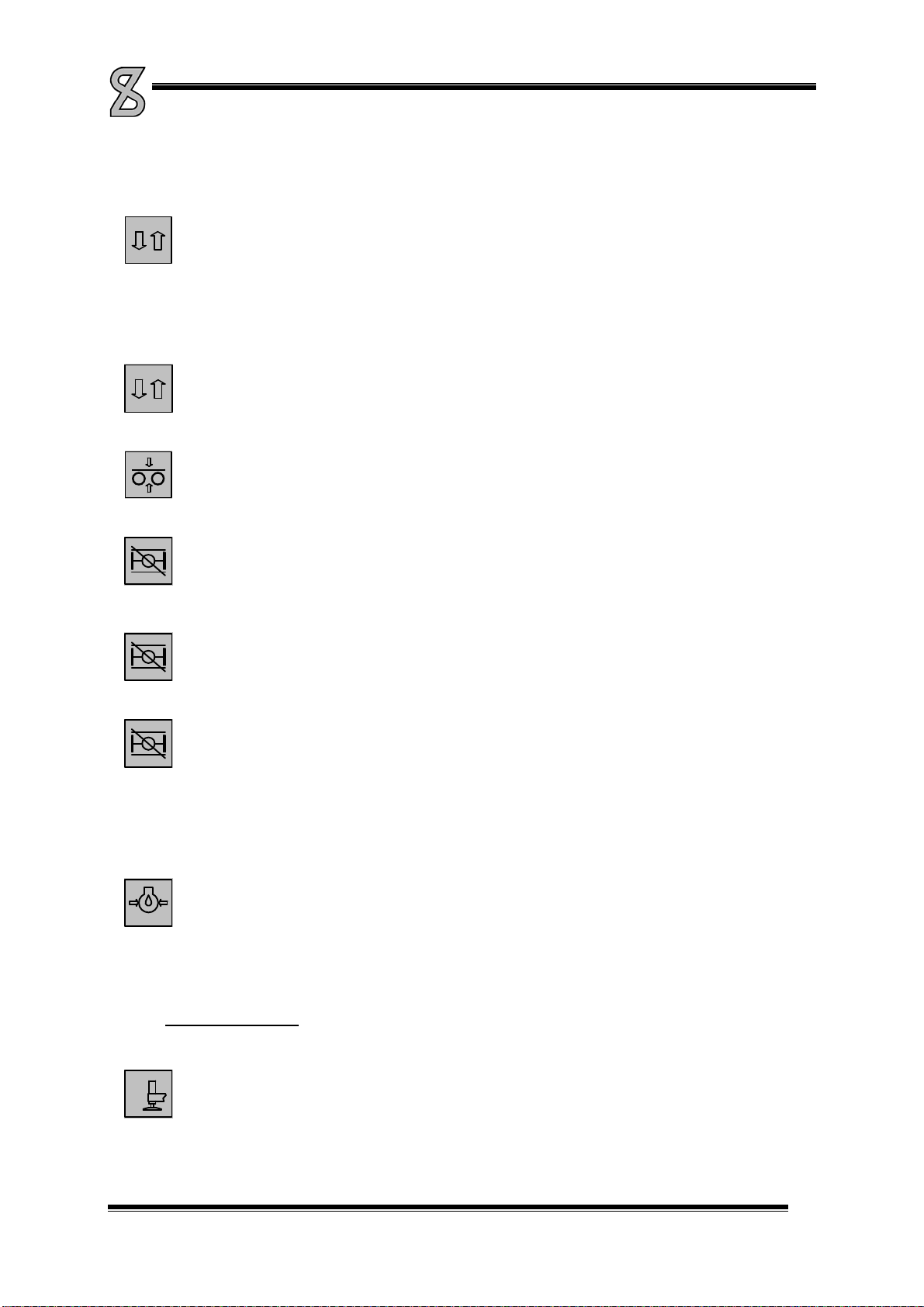
Axle Height Adjustment
13. Switch for all axles up/down
ALL
AXLES
With this switch the cylinders of all axles are moved in and out simultaneously (e.g. when
supporting the crane on outriggers).
14. Switch axles 1 and 2 up/down
AXLES
1-2
With this switch the cylinders of axles one and two can be moved in and out.
MANUAL SPIERINGS TRUCK AT5
AT5-UK-030626 01-12-09 2-10
15. Switch axle 3 left-hand side up/down
LEFT
3-4(-5)
With this switch the cylinders on the left side of the third, fourth and fifth axle can be moved in and
out.
16. Switch axle 3 right-hand side up/down
RIGHT
3-4(-5)
With this switch the cylinders on the right side of the third, fourth and fifth axle can be moved in and
out.
17. Switch/indicator lamp levelling
18. Switch/indicator lamp driving/blocking.
19a Indicator lamp off the road mode
19b Indicator lamp blocking
20. Indicator lamp max. pressure outrigger-/suspension system
This lamp goes on and a buzzer sounds at the rear outriggers as soon as the pressure in the
outrigger/suspension system becomes too high. This may happen when the outriggers, the axles or
the outrigger beams are fully in or out, or because there is an obstacle in the way when extending
the outrigger beams.
During leveling operation and when moving the axles up or down, this light could also go on. This
does not present a problem.
If there’s no action of the outrigger-/suspension system, the lighting of this lamp means, that an
error is occurred.
Outrigger Operation
(on the dashboard from left to right)
22. Switch outrigger beam front left-hand side retract/extend

MANUAL SPIERINGS TRUCK AT5
AT5-UK-030626 01-12-09 2-11
23. Switch outrigger front left-hand side retract/extend
24. Switch outrigger beam rear left-hand side retract/extend
25. Switch outrigger rear left-hand side retract/extend
26. Switch outrigger front right-hand side retract/extend
27. Switch outrigger beam front right-hand side retract/extend
28. Switch outrigger rear right-hand side retract/extend
29. Switch outrigger beam rear right-hand side retract/extend
30. Switch outrigger controls on/of
f
Switch off the outrigger controls when the outriggers are not operated or when the crane is rigged
up/rigged down or in operation. The remote control is also de-activated. Failing to switch off the
controls means the crane can not be set to the full hoisting program (full support base).
32. Ignition lock
By turning the key to the right, three positions are possible, from left to right:
0 = ignition off
1 = ignition on
2 = flame start system (push the key before turning)
3 = starting
33. Rpm/speed control.
With the speed control you can keep your current speed constant without using the accelerator
pedal. The speed control doesn’t work at a speed under 30 km/h.
Set: Switch on and adjusting the speed control.
If you are at the desired speed, move the lever to “set”. The speed control will
hold on to this speed.
If the speed control is already switched on, the speed will increase by keeping
the lever to “set”. If the speed control is switched on, you still can accelerate
by using the accelerator pedal.
When the switch “increased rpm” is switched on, you can adjust the rpm of the
engine with this lever.
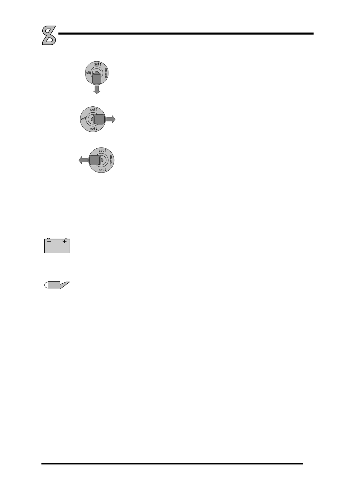
MANUAL SPIERINGS TRUCK AT5
AT5-UK-030626 01-12-09 2-12
By moving the lever to setyou can decrease the speed. Keep the lever down
until you reach the desired speed.
Memo: When you brake or press the clutch, the speed control will switch off. By
moving the lever to “memo”, the speed control will switch on again. It will adjust
the speed back to the last saved speed (if speed >30 km/h). The shifted gear
has to be the same as the last time you set the speed control.
The memory will reset when you shut down the engine.
Of
f
: You can switch off the speed control by moving the lever to “off”. The
speed control will also switch off by braking, pressing the clutch and in case of
an accident.
Tip-up,Tip-down:
When you move the lever briefly to “set” or “set”, you will increase or decrease the speed with
one km/h. The difference between the current speed and the new adjusted speed can not be more
than 5 km/h.
34. Voltmeter batteries
On this meter you can read the battery condition. The meter must be in the middle (approx. 24 Volt)
35. Oil-pressure gauge lubrication circuit
When starting this gauge will read approx. 5 bar. As soon as the oil is warm approx. 3 bar.
36. Retarder (Optional)
Refer to “Slowing down using the retarder”
37. Lever parking brake
By pulling this lever. backwards the parking brake is engaged. Pulling out the knob and pushing the lever
forwards will release the parking brake. To release the parking brake, the pressure must be at least 5.5 bar.
38. Speedometer/tachograph
The truck is equipped with a VDO tachograph. On this device you can read the driving speed and the
number of kilometres driven. The tachograph also contains a clock (1). This clock drives a diagram disc. On
this disc the activities of the driver are written by means of scribers. The disc can be replaced by opening
slot 2 (See Picture 2-9). Never leave a disc in the tachograph for longer than 24 hrs (else it would overwrite
itself). In case there is no disc in the tachograph, indicator lamp 3 will light up.
By means of switches 4 and 5 the drivers' activities can be shown. Indicator lamp 3 goes on as soon as the
driving speed exceeds 80 km/h. When at a certain speed button 6 is pressed, exceeding this speed will light
up the indicator lamp. However, when the ignition is switched off, the indicator lamp will be set to 80 km/h.
The clock may be set to the correct time by operating wheel A.
For more details on how to use the tachograph we refer to the tachograph manual (in the glove
compartment).
Table of contents
Other SPIERINGS Truck manuals


