manuals.online logo
Brands
  1. Home
  2. •
  3. Brands
  4. •
  5. Sporlan
  6. •
  7. Control Unit
  8. •
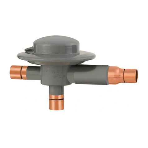
  9. Sporlan ORIT-10 Installation and maintenance instructions

Sporlan ORIT-10 Installation and maintenance instructions

FOR USE ON REFRIGERATION and/or AIR CONDITIONING SYSTEMS ONLY
COPYRIGHT 2003 BY SPORLAN VALVE COMPANY, WASHINGTON, MO 63090
Installation & Service Instructions
ORIT-6 & ORIT-10
EVAPORATOR PRESSURE
REGULATING VALVES
Installation Instructions
To insure best performance, evaporator pressure regulating
valves must be selected and applied correctly. This is covered
thoroughly in Bulletin 90-20. However, proper installation
procedures are equally as important. All of the information in
the Application Section should be reviewed before installing
ORIT valves.
VALVE LOCATION – ORIT's must be installed upstream of
any other suction line controls or accessories. These valves
may be installed in any position . . . whichever best suits the
application and permits easy adjustment and accessibility.
However, consideration should be given to locating these valves
so that they don't act as an oil trap or that solder cannot run into
the internal parts during brazing in the suction line. Since these
valves are hermetic, there is no way to disassemble them to clean
out any solder that gets trapped in the internal parts.
STRAINER – Catch-All Filter-Drier®– See•All®Moisture
and Liquid Indicator – Just as with any refrigerant flow
control device, the need for an inlet strainer is a function of
system cleanliness and proper installation procedures. To in-
stall the strainer, the tubing is inserted in the valve connection
until the tubing and the strainer flange ring are up against the
tubing stop, thus locking the strainer in place. See Figure 1.
Moisture and particles too small for the inlet strainer are
harmful to the system and must be removed. Therefore, it is
recommended that a Catch-All Filter-Drier be installed accord-
ing to the application recommendations in Bulletin 40-10.
Further system protection is easily and inexpensively pro-
vided with the installation of a See•All Moisture and Liquid
Indicator on every system. Complete information is given in
Bulletin 70-10.
BRAZING PROCEDURES – When installing ORIT's with
solder connections, the internal parts must be protected
by wrapping the valve with a wet cloth to keep the body
temperature below 250°F. The tip of the torch should be
large enough to avoid prolonged heating of the connections.
Overheating can also be minimized by directing the flame
away from the valve body.
Any of the commonly used solders may be used with these
copper connections. The key points to remember are: avoid
overheating the valve and avoid running solder into the inter-
nal parts of the valve.
The valve core of the access valve is shipped in an envelope
attached to the access valve. If the access valve connection is
to be used as a reusable pressure tap to check the valve set-
ting, the ORIT must be brazed in before the core is installed
to protect the synthetic material of the core. If the access
valve is to be used as a permanent pressure tap for any rea-
son, the core and access valve cap may be discarded.
TEST and OPERATING PRESSURES – Inert dry gases
such as nitrogen, CO2 or helium are often used for leak detec-
tion. Excessive leak testing or operating pressures may dam-
age these valves by reducing the life of the bellows.
CAUTION: Inert gases must be added to the system
carefully through a pressure regulator. Unregulated
gas pressure can seriously damage the system and
endanger human life. Never use oxygen or explosive
gases. The table below lists the maximum pressure
each valve can withstand without damage.
VALVE SETTING and ADJUSTMENT – The standard
factory setting for the 0/50 psig range is 30 psig and for the
30/100 psig range it is 60 psig. Since these valves are adjust-
able, the setting may be altered to suit the specific system
requirements.
The main function of an ORIT valve is to keep the evapora-
tor pressure above some given point at minimum load condi-
tions. Therefore, even though the valves are selected on the
basis of the pressure drop at full load conditions, they should
be adjusted to maintain the minimum allowable evaporator
pressure under the actual minimum load conditions.
EPYTEVLAVgisp–ERUSSERPMUMIXAM
6-TIRO003
01-TIRO002
Figure 1
Suction
Line
Valve Inlet
Connection
Strainer
Tubing Stop
equate time between adjustments are recommended to allow
the system to balance at the new setting.
When ORIT's are installed in parallel, each should be adjust-
ed the same amount. If one valve has been adjusted more than
the other, best performance will occur if both are adjusted all
the way in before resetting them an equal amount.
Service Instructions
Since these valves are hermetic and cannot be disassembled
for inspection and cleaning, they usually must be replaced if
they become inoperative. However, if an ORIT fails to
open, close properly, or won't adjust, it is probably due
to solder or other foreign materials lodged in the port. It is
sometimes possible to dislodge these materials by turning the
adjustment nut all the way out with the system running.
If the ORIT develops a refrigerant leak around the spring hous-
ing, it probably has been overheated during installation or the
bellows has failed due to severe compressor pulsations. The
valve should be cut out of the line to allow it to be tested with-
out further damage. In either case the valve must be replaced.
When this occurs, the ORIT will close until the inlet pressure
becomes greater than the outlet and spring pressures. Then the
valve will open and close like a pressure differential valve.
TYPICAL
INSTALLATIONS
When adjusting both evaporator pressure regulators and
thermostatic expansion valves, the following procedure is
recommended:
With the expansion valve at the Sporlan factory setting or at
a manufacturer's predetermined set point, and under the
actual minimum load condition, the evaporator pressure reg-
ulator should be adjusted to the desired setting. Finally, if
necessary, the thermostatic expansion valve or valves can be
adjusted to the desired superheat setting while under the
design condition.
To adjust these valves, remove the cap and turn the adjust-
ment screw with the proper size hex wrench (1/4" for ORIT-
6: and 5/16" for ORIT-10). A clockwise rotation increases the
valve setting while a counterclockwise rotation decreases the
setting. To obtain the desired setting, a pressure gauge should
be utilized on the inlet side of the valve so the effects of any
adjustments can be observed. The ORIT has an access valve
on the inlet fitting for this purpose. Small adjustments and ad-
Printed in U.S. of A. Form SD-73-20-803
EPYTEVLAV NRUTREPEGNAHCISPEGAREVA
egnaR.jdA05/0egnaR.jdA001/03
6-TIRO6 31
01-TIRO5.25.5
Evaporator
Distributor
See•All
TEV
Catch-All
Receiver
Condenser
Compressor
Access
Valve
ORIT
External Equalizer
Evaporator
A
Evaporator
B
From Receiver
ORIT ORIT
Access Valve
Access Valve
To Condenser
Compressor
Liquid Line To
Other Evaporators
Suction Line From
Other Evaporators
Distributor Distributor

This manual suits for next models

1

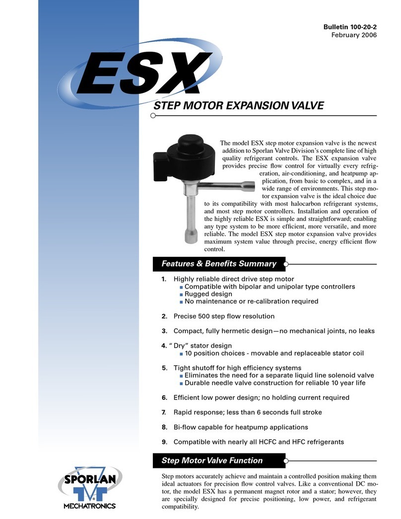
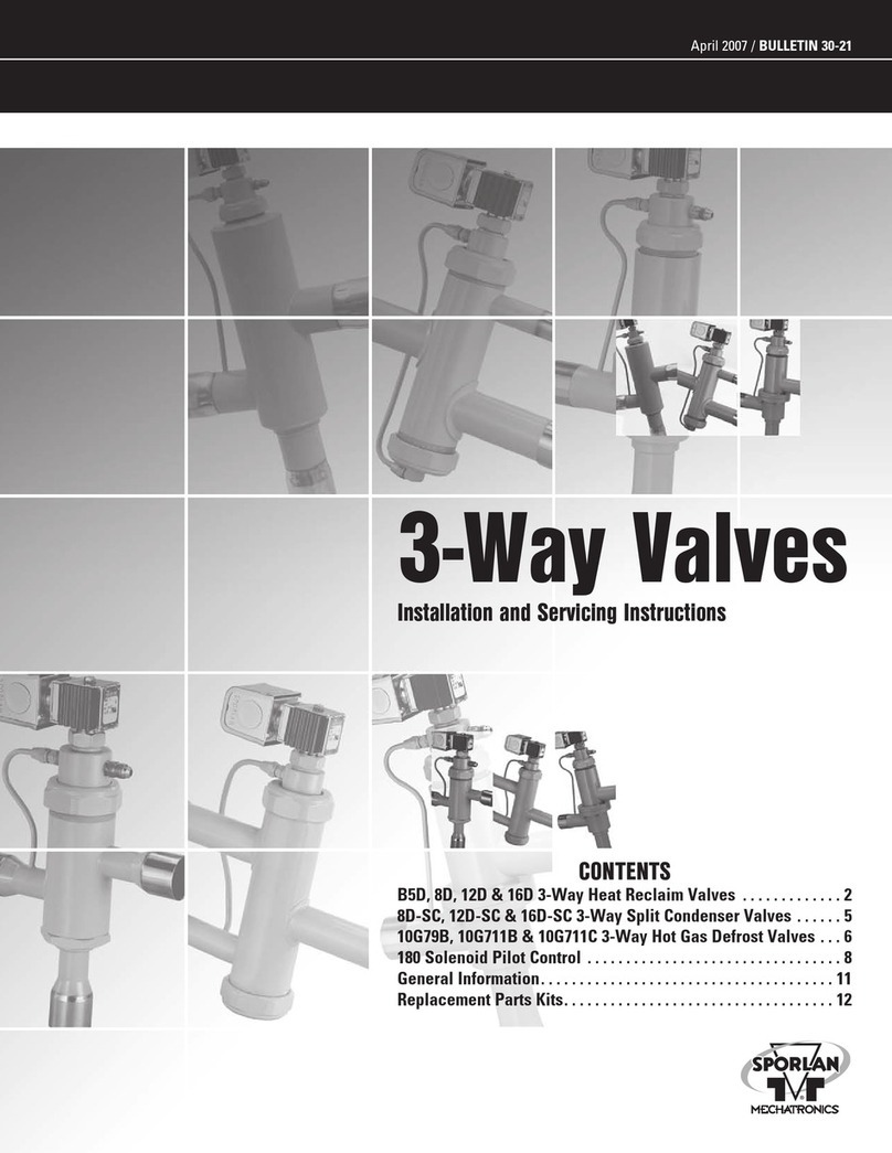
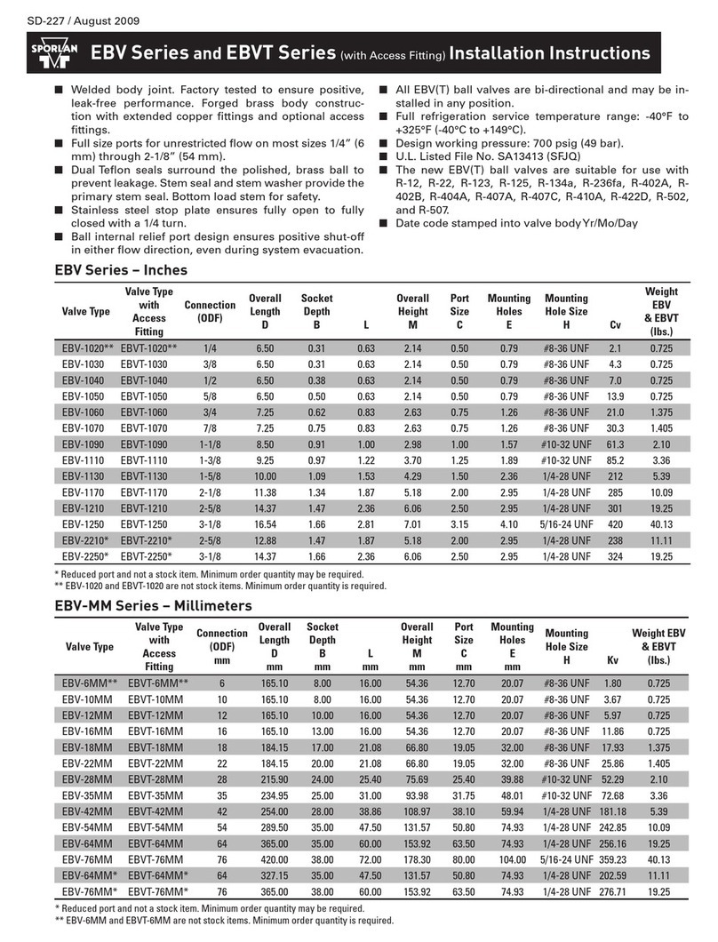
Other Sporlan Control Unit manuals

Sporlan B5D User guide

Sporlan

Sporlan B5D User guide

Sporlan EBV Series User manual

Sporlan

Sporlan EBV Series User manual

Sporlan ORIT-12 Installation and maintenance instructions

Sporlan

Sporlan ORIT-12 Installation and maintenance instructions

Sporlan Parker S3C User guide

Sporlan

Sporlan Parker S3C User guide

Sporlan OROA-5 Installation and maintenance instructions

Sporlan

Sporlan OROA-5 Installation and maintenance instructions

Sporlan Secondary Fluid Control User manual

Sporlan

Sporlan Secondary Fluid Control User manual

Sporlan SDR-4 Quick guide

Sporlan

Sporlan SDR-4 Quick guide

Sporlan ESX User manual

Sporlan

Sporlan ESX User manual

Popular Control Unit manuals by other brands

Fluke DTX-MFM2 user manual

Fluke

Fluke DTX-MFM2 user manual

Tyco iSTAR Ultra Installation and configuration guide

Tyco

Tyco iSTAR Ultra Installation and configuration guide

Dialog DA1458 Series user manual

Dialog

Dialog DA1458 Series user manual

EWM T4.06-Tetrix AC/DC Smart 2.0 operating instructions

EWM

EWM T4.06-Tetrix AC/DC Smart 2.0 operating instructions

Honeywell S8910U Installation instructions and safety information

Honeywell

Honeywell S8910U Installation instructions and safety information

Viessmann 5221 Operation manual

Viessmann

Viessmann 5221 Operation manual

Phasemation CM-2000 owner's manual

Phasemation

Phasemation CM-2000 owner's manual

Texas Instruments bq24165 user guide

Texas Instruments

Texas Instruments bq24165 user guide

DSC AMP-704 installation instructions

DSC

DSC AMP-704 installation instructions

Erreka VIVO-M202 Diagram

Erreka

Erreka VIVO-M202 Diagram

Parker Hydraulics D1VA Series Service bulletin

Parker Hydraulics

Parker Hydraulics D1VA Series Service bulletin

Rise MAX.CP installation manual

Rise

Rise MAX.CP installation manual

Carrier 50CJ Installation, operation and maintenance instructions

Carrier

Carrier 50CJ Installation, operation and maintenance instructions

uniLIGHT BLACK.1 manual

uniLIGHT

uniLIGHT BLACK.1 manual

Toshiba IK-CT2D instruction manual

Toshiba

Toshiba IK-CT2D instruction manual

Epson RC620+ manual

Epson

Epson RC620+ manual

Freescale Semiconductor TWR-KL25Z user manual

Freescale Semiconductor

Freescale Semiconductor TWR-KL25Z user manual

Emerson Crosby JOS-E Series Installation and maintenance instructions

Emerson

Emerson Crosby JOS-E Series Installation and maintenance instructions

manuals.online logo
manuals.online logoBrands
  • About & Mission
  • Contact us
  • Privacy Policy
  • Terms and Conditions

Copyright 2025 Manuals.Online. All Rights Reserved.