Sporlan ORIT-12 Installation and maintenance instructions

November 1999 / BULLETIN 90-21-1
EVAPORATOR PRESSURE
REGULATING VALVES
Installation & Service Instructions
(S)ORIT-12
(S)ORIT-15
(S)ORIT-20
FOR USE ON REFRIGERATION and/or AIR CONDITIONING SYSTEMS ONLY
Bulletin 90-21-1, November 1999, supersedes Bulletin 90-21-1, dated October 1995, and all prior publications.
©COPYRIGHT 1999 BYSPORLAN VALVE COMPANY, WASHINGTON, MISSOURI
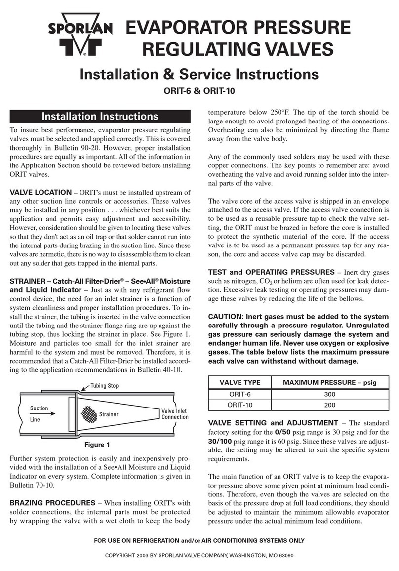
To insure optimum performance, evaporator pressure regu-
lating valves must be selected and applied correctly. This is
covered thoroughly in Bulletin 90-20-1. However, proper
installation procedures are equally important. All of the
information in the Application Section should be reviewed
before installing (S)ORIT valves.
VALVE LOCATION – The (S)ORIT-12, -15 and -20 must be
installed upstream of any other suction line controls or
accessories. They may be installed in the horizontal or verti-
cal position (Do not install upside down.) . . . whichever best
suits the application and permits easy adjustment and
accessibility. However, consideration should be given to
locating these valves so they don't act as an oil trap, or so
solder cannot run into the internal parts during brazing in
the suction line. Reverse flow is not recommended.
Therefore, a high side to low side hot gas defrost line must
be connected upstream of the (S)ORIT-12, -15 and -20.
INSTALLATION and BRAZING PROCEDURES — It is
not necessary to disassemble the valve when soldering to the
connecting lines. Any of the commonly used types of solder
(such as 50-50, 95-5, Easy-Flo, Phos-Copper or equivalents)
are satisfactory. It is important — regardless of the solder
used — to direct the flame away from the valve body and
avoid excessive heat on the diaphragm of the pilot valve. As
an extra precaution, a damp cloth may be wrapped around
the diaphragm during the soldering operation.
IMPORTANT: The pilot valve high pressure source is the
primary valve port closing force, so this connection must be
made for proper performance. There are several precautions
to observe when making this connection.
1. Generally the high pressure connection is made either to
the discharge line or the top of the receiver. If hot dis-
charge gas is used for defrost, the (S)ORIT pilot supply
line must originate from the same location as that of the
hot gas defrost line. The liquid line may also be used for
the high pressure connection. However, equipment man-
ufacturers sometime select other locations that are com-
patible with their specific design requirements.
Precautions should always be taken so this line does not
serve as an oil trap.
The pilot supply line should be kept as short as possible to
minimize condensing. Alternate feeding of gas and liquid to
the pilot supply may cause the valve to operate erratically.
2. It is also recommended that a hand valve or solenoid
valve (Sporlan A3) be installed in this line so the pilot
can be isolated should servicing become necessary. The
hand valve or solenoid valve is mandatory if it is neces-
sary to pump out an evaporator for service or for a pump-
down system. Closing the hand valve or solenoid valve
will cause the main piston to shift to the full open posi-
tion for rapid evacuation of the evaporator. The positive
closure of the pilot supply line is also necessary on pump-
down systems to eliminate the high side to low side
equalization path.
The (S)ORIT-12, -15 and -20 are normally open and by
closing off the pilot supply pressure (closing pressure), the
(S)ORIT main piston will shift to the full open position.
3. To insure proper performance, the high pressure source
supplied to the inlet of the pilot valve must be at least 50
psi above the outlet suction pressure of the (S)ORIT
evaporator pressure regulator.
TEST PRESSURES and DEHYDRATION TEMPERA-
TURES — For better leak detection, an inert dry gas, such
as nitrogen or CO2, may be added to an idle system.
CAUTION: Inert gases must be added to the system care-
fully through a pressure regulator. Unregulated gas pres-
sure can seriously damage the system and endanger human
life. Never use oxygen or explosive gases.
Excessive pressure can shorten the life of the pilot regu-
lator valve diaphragm. The maximum low side test pres-
sure that can safely be applied is 450 psig. This maximum
pressure is well above the minimum field leak test pres-
sures for low side listed in the ANSI/ASHRAE Standard
15-1994.
The maximum dehydration temperature the valve body can
be subjected without danger is 250°F.
VALVE SETTING and ADJUSTMENT — The standard
factory setting for the 0/100 psig range is 30 psig. The main
function of an (S)ORIT valve is to keep the evaporator pres-
sure above some given point at minimum load conditions.
Therefore, even though the valves are selected on the basis
of pressure drop at full load conditions, they should be
adjusted to maintain the minimum allowable evaporator
pressure under the actual minimum load conditions.
When adjusting both evaporator pressure regulating valves
and thermostatic expansion valves, the following procedure
is recommended.
®
INSTALLATION INSTRUCTIONS
ORIT
(S)ORIT

EZISDNAEPYTEVLAV
TIROTIROS
REBMUNTRAPNOITPIRCSED 21 51 0221 5102
DERIUQERYTITNAUQ
YLETARAPESDLOSSTRAPTNEMECALPER
2420-100ROTPADA 1 1
2420-200ROTPADA 1 1
2420-000EGNALFYDOB 1 1
2420-300EGNALFYDOB 1 1
2620-510WERCSPAC 4 4
2620-520WERCSPAC 4 4
03184-3 WERCSLIOC 1 11
3520-900TEKSAG 1 1
624 0-500TEKSAG 1 1 1 1
1-18631 TUNKCOL 1 1
260-182GNIR-O 1
260-113GNIR-O 1 1
342 0-300etaDmorfelytStunkcoLebuTgnisolcnE(TEKSAG
nwohStoN)tneserpot8993edoC 111
260-161hguorhtelytStunkcoLebuTgnisolcnE(GNIR-O
nwohStoN)8983edoCetaD 111
260-141)YLNOelytSwercS4ebuTgnisolcnE(GNIR-O
nwohStoN 111
424 0-500RENIARTS 1 1 1111
51141 ETALPEMANEVLAV 1 11
9420-110)"2/1-1(ROTPADATELTUO 2
9420-100)"2/1-2(ROTPADATELTUO 2
1510-700PACMOTTOB 2
J5-P40-320TEKSAGERALFREPPOC 2
STIKSTRAPEVLAVTOLIPTNEMECALPER 1
0-4-A001/ TNEMELE 1 1 1111
Y-K0011-5 ,reniartS,ylbmessAtoliP:edulcnistiKllA
.swercSpaCdna)s(teksaG
111
Y-K0101 111
STIKSTRAPLANRETNITNEMECALPER
KO-SR1-I23ehT.gnirpSdnanotsiP,)s(teksaG:edulcnistiKllA
51-ADC/IRO-SKehT.rotpadAehtsedulcniosla21-IRO-SK
.gniR-OdnaeveelSydoBasedulcni02-ADC/IRO-SKdna
1 1
KO-SDC/IR1-A5 1 1
KO-SDC/IR2-A0 1 1
REPLACEMENT PARTS AND PARTS KITS
①The pilot valve is available with or without the solenoid stop valve. The solenoid stop valve is not available separately and should not be removed from the pilot regulator.
②This part may be necessary to adapt a new pilot to some obsolete valves.
③Replacement (S)ORIT-12 internal parts are only compatible with the Y1005 and Y1010 pilot valves. When using these parts with obsolete pilot valves, the pilot valve must also be replaced.
With the expansion valve at the Sporlan factory setting, or
at a manufacturer's predetermined setpoint, and under the
actual minimum load condition, the evaporator pressure
regulating valve should be adjusted to the desired setting.
Finally, if necessary, the thermostatic expansion valve or
valves can be adjusted to the desired superheat setting
while under the normal operating load condition.
When an evaporator pressure regulating valve has been
operating for a period of time at a given setting and an
increase in the setting is required, as much as 30 minutes
may be required for the new balance to take place after an
adjustment is made. If the valve is being adjusted to a lower
setting, an immediate response to an adjustment should be
observed.
To adjust the (S)ORIT valves, turn the adjustment screw
with a 3/8" hex wrench. A clockwise rotation increases the
valve setting, while a counterclockwise rotation decreases
the setting. To obtain the desired setting, a pressure gauge
should be utilized on the inlet side of the valve so the effects
of any adjustments can be observed.
When (S)ORITs are installed in parallel, each should be
adjusted the same amount to obtain optimum performance.
If one valve has been adjusted more than the other, both
valves should be adjusted all the way in before resetting
them an equal amount.
The (S)ORIT-12, -15 and -20 can be easily disassembled for
inspection and cleaning, or for replacement of the pilot
assembly. The pilot assembly is available with (Kit number
K-Y1005) or without (Kit number K-Y1010) the solenoid
stop valve. The solenoid stop valve is not available sep-
arately and should not be removed from the pilot reg-
ulator, nor should a standard solenoid valve be added
to the pilot assembly to achieve the stop feature. The
pilot port is critically sized with an orifice in the outlet of the
pilot assembly. The pilot kits contain: 1 pilot assembly; 2
gaskets (tetraseal for (S)ORIT-12 and -15; composition gas-
ket for (S)ORIT-20), and 1 copper flare gasket for the
(S)ORIT-20.
CAUTION: The pilot assembly should be isolated from the
high pressure power source before removal, and the main
valve body should be isolated from inlet and outlet pressures.
The (S)ORIT-12, -15 and -20 are normally open and by closing
off the pilot supply pressure (closing pressure), the (S)ORIT
main piston will shift to the full open position.
Page 2 / BULLETIN 90-21-1
SERVICE INSTRUCTIONS

BULLETIN 90-21-1 / Page 3
1. Disconnect the three connections of the pilot valve. They
are:
— inlet (high pressure source)
— outlet
— external equalizer
2. With the locknut or body flange still intact, place a
wrench on the bottom fitting of the pilot valve. Turn
counterclockwise and remove the pilot assembly from
the adaptor.
5 ELEMENT
5 STRAINER
4 LOCKNUT
2 ADAPTOR
7 GASKET
2PISTON
2SPRING
1BODY
1BODY
2SPRING
6O-RING
2BODY SLEEVE
(O-RING Groove)
2 PISTON
4 ADAPTOR
1ADAPTOR
4 BODY FLANGE
5 CAP SCREW
5 OUTLET ADAPTORS
5 BOTTOM CAP
5 COPPER GASKET
1Replacement part not available.
2Part is not available separately, but is included with the Internal
Parts Kit(s).
3Part is not available separately, but is included with the Pilot
Assembly Kit(s).
4Part is available separately.
5Part is available separately, and is also included with the Pilot
Assembly Kit(s).
6Part is available separately, and is also included with the
Internal Parts Kit(s).
7Part is available separately, and is also included with the Pilot
Assembly Kit(s) and the Internal Parts Kit(s).
(S)ORIT-15 &-20
FIGURE 1
5 STRAINER
5 ELEMENT
5 COIL SCREW
5 VALVE
NAMEPLATE
3ORIT PILOT
ASSEMBLY
(without solenoid
stop valve)
3SORIT PILOT
ASSEMBLY
(with solenoid
stop valve)
OBSOLETE
ADAPTOR
PILOT REPLACEMENT INSTRUCTIONS 3. Install the new pilot assembly. (At this point the flange is
still securely bolted to the valve body.) Again place a wrench
on the bottom connection of the pilot valve. Turn clockwise
until the pilot assembly is firmly in place. Do not attempt
to align the three pilot valve connections at this time.
4. Remove the locknut or cap screws and replace the gasket
under the adaptor. Two gaskets are supplied with each
pilot assembly kit. The correct gasket for the (S)ORIT-12
and -15 is the tetraseal. The (S)ORIT-20 uses the compo-
sition gasket. See Figure 2 for actual dimensions of the
tetraseal and the gasket.
(S)ORIT-12
OR
7 GASKET

5. Reassemble the valve. Allen head cap screws must be
replaced with the hex head screws included with the pilot
assembly kit. Before completely tightening the locknut or
cap screws, rotate the pilot valve to properly align the
inlet, outlet and external equalizer connections. Join
these connections and tighten the locknut of the
(S)ORIT-12 to 30 ft. lbs. A torque value for the cap screws
on the (S)ORIT-15 and -20 is not recommended, but uni-
formity of compression from the four cap screws is impor-
tant. Screw the flange down evenly and firmly. The pilot
replacement is now complete.
T-Seal
for
(S)ORIT-12, 15
Gasket
for
(S)ORIT-20
NOITCNUFLAMESUACYDEMER
eruliaF
nepoot
.nepotroptolipgnidlohlairetamngierofrotriD.1 .troptolipnaelcdnaelbmessasiD.1
.eruliafliocevlavdionelostoliP.2 htiwlioc1-CKMehtesU.liocevlavdionelosecalpeR.2
.egatlovreporpeht
tonseoD
etaluger
setalugerro
ylhsigguls
ehtfotelniehtotdeilppusecruoserusserphgihehT.1
teltuoehtevobaisp05tsaeltaebtsumevlavtolip
.TIRO)S(ehtfoerusserpnoitcus
.ecruosrewopevlavtolipetacol-eR.1
,ecnatsidelbaredisnocfosienilylppustolipehtfI.2
.ruccoyamgnisnednoc
ehtmorfsetanigiroenilylppusfiroenilylppustolipetalusnI.2
.enilegrahcsidehtfopotehtottievomreviecerehtfopot
eruliaF
esolcot
tsorfedrof
.deggulprotuhsdehcnipenilylppuserusserphgiH.1 .enilylppuserusserphgihnaelcroecalpeR.1
seodydobevlavdnarotpadaneewtebteksagrolaes-T.2
ehtfotuodeelbnacerusserp,sruccosihtfI.laeston
.evlavtolipehtybdeilppusebnacnahtretsafrebmahc
emitynadecalperebdluohsesehT.teksagrolaes-TecalpeR.2
.ydobevlavehtmorfdevomersiylbmessatolipeht
dnanotsipneewtebdegdolrehtielairetamngierofrotriD.3
eveelsehtnignirocsevissecxeropu-gnahgnisuaceveels
ehtfotuodeelboterusserphgihehtgniwollanotsipehtro
.notsipehtevobarebmahc
.eveelsehtdnanotsipehtecalperyrassecenfironaelC.3
.lairetamngierofhtiwdeggulptolipotreniartstelnI.4 .reniartsecalperronaelC.4
tolipehtnilioybdetcirtsersitoliphguorhtwolftnaregirfeR.5
hcumootroenilylppusdeppartaoteudrehtieenilylppus
.metsysehtnilio
dnaneposititahterusebotenilylppustolipehtkcehC.5
.partlionasaevrestonseodtitahtdna
ecruoserusserprewolamorfsetanigiroerusserpylppustoliP.6
.tsorfedrofdesusinaht
ehtfopotehtmorfsetanigiroecruoserusserptolipehtfI.6
ehtevomtsorfedrofgnisolctonsievlavehtdnareviecer
.enilegrahcsidehtotecruoserusserpylppustolip
Page 4 / BULLETIN 90-21-1
FIGURE 2
PRINTED IN U.S. OF A. 35-1199
PISTON REPLACEMENT
SERVICE TIPS
(S)ORIT-12:
1. Remove the pilot assembly from the adaptor as described
in Steps 1 and 2 of the pilot replacement instructions.
2. Remove the locknut and replace the adaptor, tetraseal,
piston assembly and bottom spring. Reassemble the
valve and tighten the locknut to 30 ft. lbs.
3. Reinstall the pilot assembly. Place a wrench on the bot-
tom connection of the pilot valve and turn clockwise until
the pilot assembly is firmly in place. Do not attempt to
align the three pilot valve connections at this time.
4. Loosen the locknut and rotate the pilot valve to properly
align the inlet, outlet and external equalizer connec-
tions. Join these connections and tighten the locknut to
30 ft. lbs.
(S)ORIT-15 &20:
1. Disconnect the three connections of the pilot valve and
remove the four cap screws. The complete pilot assembly
adaptor and body flange can now be lifted off the main
valve body.
2. Replace the piston assembly, body sleeve and bottom
spring.
3. Install a new gasket and reassemble the valve. Before com-
pletely tightening the cap screws, rotate the pilot valve to prop-
erly align the inlet, outlet and external equalizer connections.
Join these connections and tighten the cap screws. A torque
value for the cap screws is not recommended but uniformity of
compression from the four cap screws is important. Screw the
flange down evenly and firmly.
This manual suits for next models
5
Other Sporlan Control Unit manuals

Sporlan
Sporlan B5D User guide

Sporlan
Sporlan Parker S3C User guide

Sporlan
Sporlan ESX User manual

Sporlan
Sporlan EBV Series User manual

Sporlan
Sporlan OROA-5 Installation and maintenance instructions

Sporlan
Sporlan SDR-4 Quick guide

Sporlan
Sporlan Secondary Fluid Control User manual

Sporlan
Sporlan ORIT-10 Installation and maintenance instructions
Popular Control Unit manuals by other brands

Carrier
Carrier 50CJ Installation, operation and maintenance instructions

uniLIGHT
uniLIGHT BLACK.1 manual

Toshiba
Toshiba IK-CT2D instruction manual

Epson
Epson RC620+ manual

Freescale Semiconductor
Freescale Semiconductor TWR-KL25Z user manual

Emerson
Emerson Crosby JOS-E Series Installation and maintenance instructions