Sporlan SDR-4 Quick guide

ELECTRIC
DISCHARGE
BYPASS
VALVES
®
Installation and Service Instructions
SDR-3 and SDR-4
SYSTEM CONSIDERATIONS
The discharge bypass valve is applied in a branch line off
the discharge line as close to the compressor as possible.
The bypassed vapor can enter the low side at one of the fol-
lowing locations:
1. Evaporator inlet with distributor.
2. Evaporator inlet without distributor.
3. Suction line.
Each is illustrated and discussed below.
BYPASS TO EVAPORATOR INLET
WITH DISTRIBUTOR
This method of application, illustrated in Figure 1, offers
distinct advantages over the other methods, especially for
unitary or field built-up units where the high and low side
are close coupled. The primary advantage of this method is
that The EDBV can directly control the temperature of the
cooled fluid. A sensor placed in the air off the evaporator or
on the chilled water line of a chiller can cause the EDBV to
modulate to maintain the desired temperature. In addition,
the system thermostatic expansion valve will respond to the
increased superheat of the vapor leaving the evaporator and
will provide the liquid required for desuperheating. The
evaporator serves as an excellent mixing chamber for the
bypassed hot gas and the liquid-vapor mixture from the
expansion valve. This ensures a dry vapor reaching the
compressor. Oil return from the evaporator is also improved
since the velocity in the evaporator is kept high by the hot
gas. Piping for this method of application can be accom-
plished by the use of a Sporlan 1650R series distributor on
a new application, or a Sporlan Auxiliary Side Connector
(ASC) when adding the valve to a system with distributor.
NOTE: If the distributor circuits are sized properly
for normal cooling duty, the flow of hot gas
through the circuits may cause excessive pressure
drop and/or noise. Therefore, it is recommended
that the distributor circuits be selected one size
larger than for straight cooling duty. For complete
technical details on the 1650R series distributor
and the ASC series Auxiliary Side Connector, refer
to Bulletin 20-10.
VALVE / EQUIPMENT LOCATION
AND PIPING
When the evaporator is located below the compressor on a
remote system, bypass to the evaporator inlet is still the
best method of hot gas bypass to insure good oil return to
the compressor. When this is done, the bypass valve must
be located at the compressor rather than at the evaporator
section. This will insure obtaining rated capacity from
the bypass valve at the conditions for which it was
selected. If the evaporator is above or on the
same level as the compressor, this valve
location will also eliminate the possibility
of hot gas condensing in the long
bypass line and running back into
the compressor during the off
cycle. Whenever hot gas
bypass to the evaporator
inlet is necessary for a
system with two or
more evaporator
External Equalizer
Compressor
Solenoid
Valve
TEV
Catch-All
Condenser
Receiver
Distributor
Evaporator
SDR 4
See•All
Return Air
TCB
Figure 1
SD-244 3/19/01 1:03 PM Page 3

sections each with its own TEV (no liquid line solenoid
valves) but handling the same load, two methods may be used
to avoid operating interference between sections:
1. Use a separate discharge bypass valve for each evaporator
section.
2. Use one discharge bypass valve to feed two bypass lines
each with a check valve between the bypass valve and the
evaporator section inlet. The check valves will prevent
interaction between the expansion valves when the bypass
valve is closed.
CAUTION - Introduction of the bypassed gas
between the thermostatic expansion valve and
the distributor is not generally recommended.
Hot gas flowing through the distributor nozzle
and circuit tubes, that were sized for normal cool-
ing flow rates, causes excessive pressure drop.
Careful evaluation and testing should precede
any application where hot gas is bypassed
between the TEV and the distributor.
BYPASS TO EVAPORATOR INLET
WITHOUT DISTRIBUTOR
Many refrigeration systems and water chillers do not use
refrigerant distributors, but may require some method of com-
pressor capacity control. This type of application provides the
same advantages as bypassing hot gas to the evaporator inlet
with a distributor. All information relating to bypassing hot
gas to the evaporator inlet with a distributor, except that con-
cerning distributors or ASC’s, also applies to bypassing to the
evaporator inlet without a distributor.
BYPASS TO SUCTION LINE
On many applications, it may be necessary to bypass directly
into the suction line (fig. 2). This is generally true of systems
with multi-evaporators or remote condensing units, as well as
on existing systems where it is easier to connect to the suction
line than the evaporator inlet. When hot gas is introduced
directly into the suction line, the danger of overheating the
compressor and trapping the oil in the evaporator exists. As
the suction temperatures rise, the discharge temperature like-
wise starts to increase. This can cause breakdown of the oil
and refrigerant with the possible result being a compressor
burnout. This method offers added flexibility for multi-evap-
orator systems or remote systems because the hot gas bypass
components can be located at the condensing unit. However,
to insure oil return, special care must be taken in the system
piping.
DESUPERHEATING THERMOSTATIC
EXPANSION VALVE
On those applications where the hot gas must be bypassed
directly into the suction line downstream of the main expan-
sion valve’s bulb, an auxiliary thermostatic expansion valve
(commonly called a desuperheating TEV or a liquid injection
valve) is required. The purpose of this valve is to supply
enough liquid refrigerant to cool the hot discharge gas to the
recommended suction temperature. Most compressor manu-
facturers specify a maximum suction gas temperature of 65°F.
For these requirements, special desuperheating thermostatic
charges are available which will control at the proper super-
heat to maintain the suction gas at or below 65°F. For appli-
cations requiring suction gas temperatures appreciably below
65°F, contact Sporlan Valve Company or the compressor man-
ufacturer for assistance. In all cases the maximum per-
missible suction gas temperature published by the
compressor manufacturer must be followed.
INSTALLATION INSTRUCTIONS
External Equalizer
Compressor
Solenoid
Valve
TEV
Catch-All
Condenser
Receiver
Distributor
Evaporator
SDR 4
DesuperheatingTEV
See•All
Return Air
TCB
Figure 3
External Equalizer
Compressor
Solenoid
Valve
TEV
Catch-All
Condenser
Receiver
Distributor
Evaporator
SDR 4
See•All
Return Air
TCB
Figure 2
Page 2
SDR-3 Figure 4
SD-244 3/19/01 1:03 PM Page 4

The valves have copper connections and any solder or brazing
alloy may be used to install the valve. There is no need to dis-
assemble the valve for installation, however, the torch flame
should be directed away from the motor housing and cable.
Care must be taken to assure that the cable is not damaged
either directly from the flame, or indirectly from contact with
hot piping. The valve is shipped in the open position to pre-
vent heat being conducted into the motor, but it is strongly
suggested that the valve body be wrapped with a wet cloth
during the soldering operation. The valve should be com-
pletely installed before connecting to the controller and apply-
ing power. The wiring is color-coded and the controller
manufacturer should be consulted for the proper attachment to
the controller.
FIELD SERVICING INSTRUCTIONS
The following steps are necessary for the proper disassembly,
inspection, cleaning and reassembly of the SDR valves
(whether in or out of the refrigerant piping).
1. Before disassembling the valve, be sure the refrigerant
pressure in the system has been reduced to a safe level
(0 PSIG).
2. Disconnect the line voltage to the valve controller.
3. Refer to the exploded view of the SDR valves (Figures
4 and 5) for the remaining instructions. Using the appro-
priate wrenches or a vice to properly support the valve
body, remove the motor assembly from the valve body by
loosening the lock nut. To prevent permanent
damage to the motor, DO NOT attempt to disas-
semble the motor housing.
CAUTION - Regardless of whether the valve is in
the system or in a vise, care must be take to pre-
vent distorting the valve parts when tightening.
4. The motor assembly may be removed for inspection and
cleaning.
5. If the motor fails to operate properly, check the resistance
of each motor phase. Resistance between the black and
white leads or between the red and green leads should be
approximately 75 ohms. Differences of more than 10%
between phases indicate a defective motor. Resistance
between black and red, or any lead and housing should be
infinite, any resistance reading will indicate a shorted
winding and the motor will need to be replaced.
6. If you have access to a SMA-12 test instrument, operation
of the valve may be proven. Connect the motor leads to the
proper color-coded connector on the SMA. Set the rate to
200 PPS and toggle in the "OPEN" direction. The piston or
pin should retract into the driver guide. After up to 30 sec-
onds, the driver should be fully retracted and a light click-
ing or "ratcheting" sound may be heard, this is normal to
the valves and proves operation of the motor. If the SMA
is toggled in the "CLOSE" position, after up to 30 seconds
the white polyester driver/pin should disengage the lead
screw, and can be removed. Inspect the driver for damage.
To replace the driver, toggle the SMA to the "OPEN" posi-
tion and carefully engage the driver to the lead screw.
CAUTION - Whenever the motor is powered while
not in place on the valve, the driver must be fully
retracted into the guide before the valve is
reassembled. Failure to do this will permanently
damage the valve.
7. If the motor responds to step 6 above, the valve body itself
should be checked for obstruction. Check for contaminants
in the port or strainer, if used.
8. If the valve body and strainer are clear and the motor oper-
ates as in step (6) above, the valve is considered opera-
tional and the problem lies in the controller or power
supply. The manufacturer of these components should be
contacted for further assistance.
MOTOR ADAPTER ASSEMBLY
REPLACEMENT
If the motor is found to be defective in the above, the entire
motor assembly must be replaced.
1. Remove all power from the valve and controller.
2. Cut the existing valve cable at a convenient point at the
driest or most protected location.
3. Splice the new cable to the old cable using the waterproof
butt splices. COLOR CODING ON THE INDIVIDUAL
WIRES MUST BE MATCHED; FAILURE TO DO SO
WILL RENDER THE VALVE INOPERATIVE AND
MAY DAMAGE EITHER THE VALVE OR CON-
TROLLER.
Page 3
SDR-4 Figure 5
SD-244 3/19/01 1:03 PM Page 5

4. Waterproof the splice with shrink tube or electrical tape
suitable for use in cold and damp environments. Care
should be taken to prevent the splice from lying in a wet
location.
VALVE REPLACEMENT
The entire valve may be replaced if desired. The old valve
may be unsoldered or cut out of the piping. If cut out, use a
tubing or pipe cutter and not a saw. When installing the new
valve any convenient brazing alloy and method may be used.
The valve need not be disassembled, but the body and motor
assembly should be wrapped with a wet cloth to prevent dam-
age.
Extra care should be taken to prevent damage to the motor
cable, either directly from the torch, or indirectly from contact
with a hot surface.
Waterproof butt splices are not supplied with complete valves,
but must be used to prevent corrosion on the motor leads
unless the cable is replaced all the way to the controller. Refer
to the instructions for MOTOR REPLACEMENT above.
If the valve is disassembled for installation, refer to
REASSEMBLY instructions, below.
REASSEMBLY
1. Use the SMA-12 in the "OPEN" mode, or use the valve
controller to retract the white polyester driver/pin fully into
the driver guide. Remove power from the valve or con-
troller.
2. Lightly oil the threads on the new motor adapter as well as
the gasket or O-ring. Carefully seat the adapter and motor
assembly on the valve body.
3. Engage and tighten the lock nut. One eighth turn more than
hand tight is sufficient to achieve a leak proof seal.
4. Pressurize the system and check for leaks.
5. Reapply power to the controller. Each controller manufac-
turer has a slightly different initialization scheme and the
proper procedure must be followed. Since, during service,
valve position as calculated by the controller will be lost,
the controller should be initialized at least twice. In some
instances, cycling power to the controller will accomplish
this. However, the controller literature or the manufacturer
should be consulted.
SMA-12 VDC BIPOLAR STEP
MOTOR ACTUATOR
1. Connect any Sporlan step motor valve to the SMA-12 by
matching wire color to terminal color. Any 12 VDC bipo-
lar step motor may be tested with the SMA-12. Phase one
leads should be connected to the black and white termi-
nals. Phase two leads should be connected to the red and
green terminals.
2. Select a step rate with the selector knob.
3. Push the open/close toggle switch in the "CLOSE" direc-
tion to extend the driver or close the valve.
4. Push the open/close toggle switch in the "OPEN" direction
to retract the driver or open the valve.
5. Observe the terminal indicator lights. At rates other than 1,
indicator lights will flash quickly. Pushing the open/close
toggle in either direction at the 1 step rate will alternate the
phases energized.
The following sequence of indicator lights will light.
6. Check that the power indicator light is lit; if not, replace
the batteries.
7. If the terminal indicator lights do not light, one or both
motor phases are open and the motor must be replaced.
8. If the motor can be powered smoothly in both directions,
the motor assembly is functional and the controller must be
tested or replaced.
SPECIFICATIONS
Power input – (2) 9 volt Alkaline batteries
Power output – 10 Watts intermittent
Step rate – Selectable – 1, 50, 100, 200 steps per second
Drive type – Bipolar
Connector – Binding post with banana plug socket
An accessory pigtail item number 958112 is available at extra
charge to allow the SMA-12 to be directly connected to all
Sporlan Packard Weather-Pack™ equipped valves.
GNINEPO GNISOLC
deR&kcalBetihW&deR
etihW&deRkcalB&deR
neerG&etihWneerG&kcalB
kcalB&neerGetihW&neerG
dfdffdfdff
PRINTED IN THE U.S. OF A. SD-244-5-1000
Page 4
SD-244 3/19/01 1:03 PM Page 2
This manual suits for next models
1
Other Sporlan Control Unit manuals
Sporlan
Sporlan ORIT-10 Installation and maintenance instructions
Sporlan
Sporlan Parker S3C User guide
Sporlan
Sporlan ESX User manual
Sporlan
Sporlan B5D User guide
Sporlan
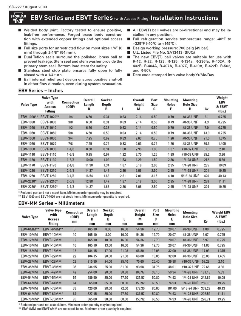
Sporlan EBV Series User manual
Sporlan
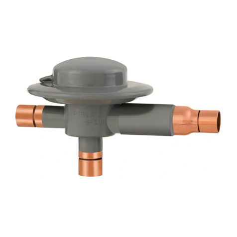
Sporlan OROA-5 Installation and maintenance instructions

Sporlan
Sporlan ORIT-12 Installation and maintenance instructions
Sporlan
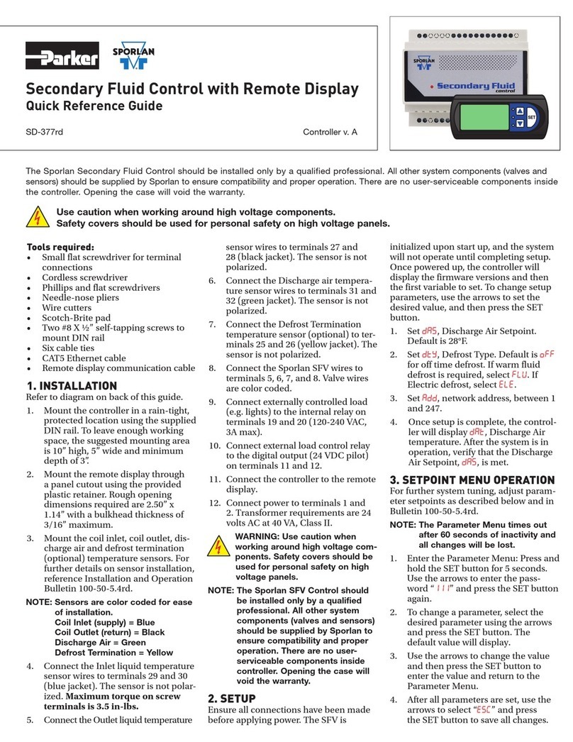
Sporlan Secondary Fluid Control User manual
