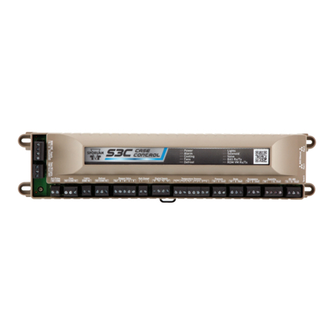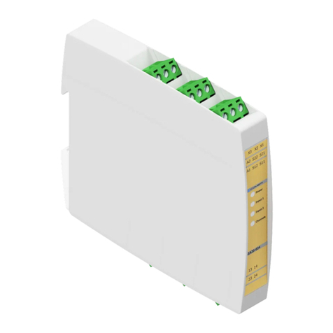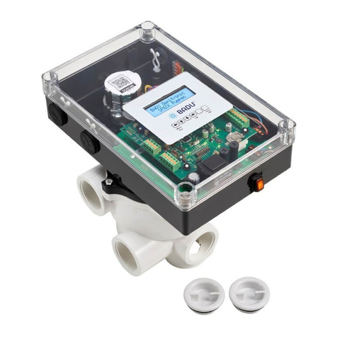
Secondary Fluid Control with Remote Display
Quick Reference Guide
The Sporlan Secondary Fluid Control should be installed only by a qualified professional. All other system components (valves and
sensors) should be supplied by Sporlan to ensure compatibility and proper operation. There are no user-serviceable components inside
the controller. Opening the case will void the warranty.
Use caution when working around high voltage components.
Safety covers should be used for personal safety on high voltage panels.
SD-377rd Controller v. A
Tools required:
• Smallflatscrewdriverforterminal
connections
• Cordlessscrewdriver
• Phillipsandflatscrewdrivers
• Needle-nosepliers
• Wirecutters
• Scotch-Britepad
• Two#8X½”self-tappingscrewsto
mountDINrail
• Sixcableties
• CAT5Ethernetcable
• Remotedisplaycommunicationcable
1. INSTALLATION
Refertodiagramonbackofthisguide.
1. Mountthecontrollerinarain-tight,
protectedlocationusingthesupplied
DINrail.Toleaveenoughworking
space,thesuggestedmountingarea
is10”high,5”wideandminimum
depthof3”.
2. Mounttheremotedisplaythrough
apanelcutoutusingtheprovided
plasticretainer.Roughopening
dimensionsrequiredare2.50”x
1.14”withabulkheadthicknessof
3/16”maximum.
3. Mountthecoilinlet,coiloutlet,dis-
chargeairanddefrosttermination
(optional)temperaturesensors.For
furtherdetailsonsensorinstallation,
referenceInstallationandOperation
Bulletin100-50-5.4rd.
NOTE: Sensors are color coded for ease
of installation.
Coil Inlet (supply) = Blue
Coil Outlet (return) = Black
Discharge Air = Green
Defrost Termination = Yellow
4. ConnecttheInletliquidtemperature
sensorwirestoterminals29and30
(bluejacket).Thesensorisnotpolar-
ized.Maximum torque on screw
terminals is 3.5 in-lbs.
5. ConnecttheOutletliquidtemperature
sensorwirestoterminals27and
28(blackjacket).Thesensorisnot
polarized.
6. ConnecttheDischargeairtempera-
turesensorwirestoterminals31and
32(greenjacket).Thesensorisnot
polarized.
7. ConnecttheDefrostTermination
temperaturesensor(optional)toter-
minals25and26(yellowjacket).The
sensorisnotpolarized.
8. ConnecttheSporlanSFVwiresto
terminals5,6,7,and8.Valvewires
arecolorcoded.
9. Connectexternallycontrolledload
(e.g.lights)totheinternalrelayon
terminals19and20(120-240VAC,
3Amax).
10. Connectexternalloadcontrolrelay
tothedigitaloutput(24VDCpilot)
onterminals11and12.
11. Connectthecontrollertotheremote
display.
12. Connectpowertoterminals1and
2.Transformerrequirementsare24
voltsACat40VA,ClassII.
WARNING: Use caution when
working around high voltage com-
ponents. Safety covers should be
used for personal safety on high
voltage panels.
NOTE: The Sporlan SFV Control should
be installed only by a qualified
professional. All other system
components (valves and sensors)
should be supplied by Sporlan to
ensure compatibility and proper
operation. There are no user-
serviceable components inside
controller. Opening the case will
void the warranty.
2. SETUP
Ensureallconnectionshavebeenmade
beforeapplyingpower.TheSFVis
initializeduponstartup,andthesystem
willnotoperateuntilcompletingsetup.
Oncepoweredup,thecontrollerwill
displaythefirmwareversionsandthen
thefirstvariabletoset.Tochangesetup
parameters,usethearrowstosetthe
desiredvalue,andthenpresstheSET
button.
1. SetdAS,DischargeAirSetpoint.
Defaultis28°F.
2. SetdtY,DefrostType.DefaultisoFF
forofftimedefrost.Ifwarmfluid
defrostisrequired,selectFLU.If
Electricdefrost,selectELE.
3. SetAdd,networkaddress,between1
and247.
4. Oncesetupiscomplete,thecontrol-
lerwilldisplaydAt,DischargeAir
temperature.Afterthesystemisin
operation,verifythattheDischarge
AirSetpoint,dAS,ismet.
3. SETPOINT MENU OPERATION
Forfurthersystemtuning,adjustparam-
etersetpointsasdescribedbelowandin
Bulletin100-50-5.4rd.
NOTE: The Parameter Menu times out
after 60 seconds of inactivity and
all changes will be lost.
1. EntertheParameterMenu:Pressand
holdtheSETbuttonfor5seconds.
Usethearrowstoenterthepass-
word“111”andpresstheSETbutton
again.
2. Tochangeaparameter,selectthe
desiredparameterusingthearrows
andpresstheSETbutton.The
defaultvaluewilldisplay.
3. Usethearrowstochangethevalue
andthenpresstheSETbuttonto
enterthevalueandreturntothe
ParameterMenu.
4. Afterallparametersareset,usethe
arrowstoselect“ESC”andpress
theSETbuttontosaveallchanges.


