SPX POWER TEAM HT75 User manual

MODEL C
IN-LINE HYDRAULIC FLOW TESTER
The 75 GPM (300l/min.) and 200 GPM (750 l/min.) inline hydraulic flow testers are compact, self-contained, portable
instruments for testing hydraulic systems in the shop or field. To simplify identification of the testers in this instruction
sheet, the two versions are identified by their English (GPM) flow capacities. Individual components are identified in
Figure 3.
SAFETY PRECAUTIONS
WARNING
●●Before operating the pump, all hose connections must be tightened with the proper tools. Do not
overtighten. Connections should only be tightened securely and leak-free. Overtightening can cause
premature thread failure or can cause high pressure fittings to split at pressures lower than their rated
capacities.
●●Should a hydraulic hose ever rupture, burst, or need to be disconnected, immediately shut off the pump.
Never attempt to grasp a leaking pressurized hose with your hands. The force of the escaping hydraulic
fluid could cause serious injury.
●●Do not subject the hose to potential hazard such as fire, sharp surfaces, heavy impact or extreme heat or
cold. Do not allow the hose to kink, twist, curl or bend so tightly that the oil flow within the hose is
blocked or reduced. Periodically inspect the hose for wear because any of these conditions can damage
the hose and result in personal injury.
●●Do not use the hose to move attached equipment. Stress may damage the hose and cause personal injury.
●●Hose material and coupler seals must be compatible with the hydraulic fluid used. Hoses also must not
come in contact with corrosive materials such as creosote-impregnated objects and some paints. Consult
the manufacturer before painting a hose. Never paint the couplers. Hose deterioration due to corrosive
materials may result in personal injury.
SET-UP
Battery Replacement and Inspection
The testers are provided with two "C" size
batteries that are pre-installed at the factory.
To replace the batteries or inspect the unit
during trouble-shooting of either a 75 or 200
GPM tester, remove the three screws #16972
holding the digital display panel #352004 and
carefully lift the panel out of the opening. Do
not damage the circuit boards or components.
There is a "LO BAT." indicator on the LCD
display that shows when the batteries are low.
Battery life can be 500 hours. There is an
automatic shut off feature after 5 minutes and
the unit will have to be powered up after a time
out. Use only new "C" size alkaline batteries as
replacements. If the batteries have been jarred
out of their holder by impact, inspect the unit for
other possible damage.
Form No. 103509
HT75
HT200
Operating Instructions for:
Sheet No. 1 of 3
Rev. Date: 28 July 2005
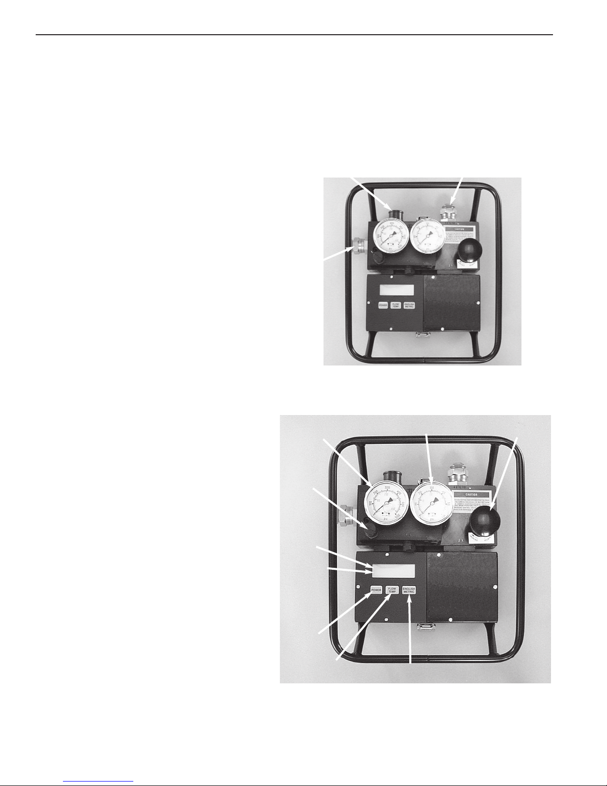
"C" SIZE
BATTERIES
DIGITAL
DISPLAY
PANEL
Figure 1
© SPX Corporation
Tech. Services: (800) 477-8326
Fax: (800) 765-8326
Order Entry: (800) 541-1418
Fax: (800) 288-7031
SPX Corporation
5885 11th Street
Rockford, IL 61109-3699 USA
Internet Address:
http://www.powerteam.com
®
Operating Instructions, Form No. 103509, Back sheet 1 of 3
Fittings
75 GPM Tester: The inlet and outlet ports (shown in Figure 2) are designed for SAE straight o-ring union adapters,
1-1/16-12 male thread by 3/4 NPSM female straight union. When the tester is not being used,
always insert the port plugs to protect the unit from damage or contamination.
200 GPM Tester: The inlet and outlet ports (shown in Figure 2) are designed for SAE Standard 1 1/2 inch, 4-bolt split
flange fittings. Flange bolts must be 1/2-13 UNC by 1 1/2 inch long SAE Grade 5 with spring
lockwashers, torqued at 55/65 ft. lbs. When the tester is not being used, always assemble the
cover plates to protect the tester from damage or contamination.
Figure 2 - TESTER CONNECTION PORTS
OUTLET
PORT
INLET
PORT
HOSE CONNECTOR
& SAFETY DISC
Figure 3
Operating Controls
HIGH
PRESSURE
GAGE
GAUGE
SNUBBER
KNOB
POWER
"ON/OFF"
SWITCH
FLOW / TEMP
(includes
bar graph)
FLOW / TEMP
SWITCH
(hold for temp)
ENGLISH / METRIC
SWITCH
PRESSURE
CONTROL
VALVE
LOW PRESSURE
GAGE
Operating Controls
Both testers have similar operating controls.
Refer to Figure 3.
POWER: Push this switch to turn the tester
ON; push to turn the tester OFF. When the
tester is not being used, the power switch
may be used to turn if off or it will
automatically shut off in five minutes.
DIGITAL DISPLAY: The display shows flow
and temperature readings, depending on the
setting of the FLOW/TEMP switch. An
analog bar at the bottom of the display
shows a real-time analog representation of
the portion of full-scale reading displayed.
LO BAT.: This indicator alerts the operator that
battery power is low, which can result in
false readings.
FLOW/TEMP: When the FLOW/TEMP switch
is held down, fluid temperature is displayed
on the meter temperature scale in either
degrees Fahrenheit and Celsius. When the
toggle switch is released, the meter returns
to its previous mode "flow". Flow is
displayed by default when the unit is on.
ENGLISH/METRIC: Units of flow or
temperature are alternately selected in
ENGLISH or METRIC whenever this switch
is pushed.
Hoses
1. Connect the pressure hose from the pump or
pressure line of the system to the tester INLET port.
2. Connect the return hose to the tester OUTLET port.
NOTE: If the hoses are connected wrong, the tester
gives flow readings but the pressure control valve
does not function. No damage to the unit occurs.
DIGITAL
DISPLAY

Operating Instructions Form No. 103509
PRESSURE CONTROL VALVE: The pressure control valve regulates system pressure by restricting the flow to
develop back pressure in the system. The control valve maintains the pressure setting during and after change in
flow. To increase pressure, turn the control valve clockwise; to reduce pressure, turn the control valve
counterclockwise.
WARNING: Before testing the system, open the pressure control valve all the way by turning
the valve counterclockwise. Increase pressure SLOWLY during the test.
NOTE:
●●Oil the pressure control valve threads regularly.
●●Each time the flow tester is connected to a hydraulic system for testing, the unit may be noisy the first
time pressure is increased with the control valve. The noise is caused by air trapped in the internal parts
of the control valve. To flush the air out, increase pressure to approximately 2000 PSI and then back to 0
PSI.
●●It may be difficult to adjust the pressure control valve when testing in a closed center system or under
high back pressure. Even when the control valve stem threads are lubricated with a good grade of oil, the
valve becomes difficult to adjust by hand at approximately 1100 PSI back pressure and almost impossible
to adjust by hand at approximately 1600 PSI back pressure.
PRESSURE GAUGES: Pressure readings are taken from the high pressure (0-6000 PSI, 0-410 BAR) and low
pressure (0-600 PSI, 0-41 BAR) gauges on the flow block. As pressure increases, the low pressure gauge gives
readings up to 500 PSI (35 BAR) and then cuts out, switching to the high pressure gauge.
GAUGE SNUBBER KNOB: A gauge snubber knob is located at the lower left corner of the gauge block. To dampen
(slow) the movement (pulsation) in the gauge needles, turn the snubber knob clockwise at a low pressure setting.
NOTE: When the gauges are dampened, the reaction time of the needles will be slow. Build pressure very
slowly to allow time for the needles to react.
OVERLOAD PROTECTION SAFETY DISC: A safety disc located at the back of the tester (See Figure 2) protects the
flow tester from extreme pressure. If pressure exceeds the ranges listed in the following chart, the disc ruptures,
relieving oil and reducing pressure before damage can occur. A hose connector surrounds the disc to act as a shield
against oil spray should the disc rupture. For more protection, a 1 1/4 inch I.D. hose should be inserted into the
connector and clamped in place. This hose should be long enough to direct oil back to the reservoir or another
container.
Safety Disc Burst Range
75 GPM 5510/6093 PSI @ 60° F
5250/5835 PSI @ 160° F
200 GPM 5220/6790 PSI @ 105° F
6000/7000 PSI @ 72° F
Sheet No. 2 of 3
Rev. Date: 28 July 2005

Operating Instructions, Form No. 103509, Back sheet 2 of 3
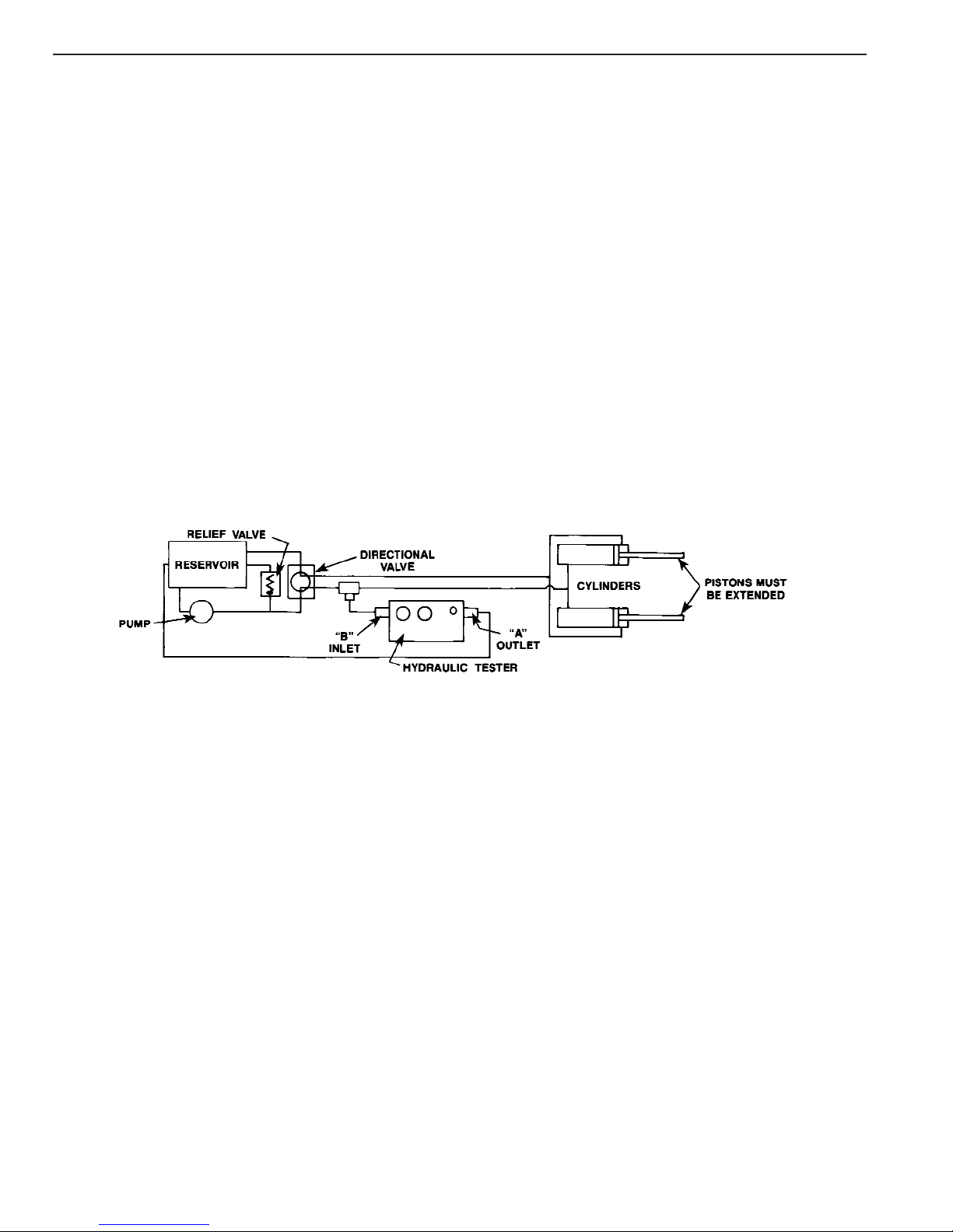
TYPICAL TESTING PROCEDURES
The following test procedures show how the tester can be used to locate a problem in the hydraulic system by
checking the efficiency of each component. In this example, the system consists of a reservoir, pump, relief valve,
directional control valve and double-acting cylinder.
EXAMPLE OF A PROBLEM: The cylinder’s piston moves out at almost normal speed under no load, but
gradually slows down as the load increases.
1. Check all hoses and connections for leakage before beginning any test.
TESTING THE PUMP (See Figure 4)
IMPORTANT: Do not allow the pressure reading on the tester gauges to exceed the maximum relief valve
pressure of the pump. Serious damage to the pump can result because the system relief valve no longer
protects the pump.
1. Shut the pump OFF, and place the control valve in the neutral position. Disconnect the line between the pump and
relief valve.
2. Connect line “A” (outlet from the tester) to the pressure port of the relief valve.
3. Connect line “B” (inlet of the tester) to the discharge port of the pump.
4. Open the pressure control valve on the tester all the way by turning the knob counterclockwise several turns. Turn
the dampener knob counterclockwise several turns.
5. Start the pump and set engine RPM for the rated speed of the pump (equipment manufacturer’s specific RPM
level for a given rate of flow).
Symptom: If the action of the gauges is erratic, and severe pulsations occur even after the dampener knob has been
adjusted, cavitation could be a problem. Solution: Check the oil level, filter and suction line.
6. Induce a load on the pump with the tester pressure control valve at approximately 50% of the maximum system
pressure. Slowly increase pressure by turning the control valve clockwise while watching the pressure gauges on
the tester.
7. When normal operating temperature is reached (per manufacturer’s specification), open the tester pressure
control valve. Record the volume at low pressure displayed on the flow display.
8. Increase pressure by turning the handle clockwise, maintaining required engine RPM at all pressure check points.
Record the volume at various increments up to maximum pressure.
9.
Open the pressure control valve
and shut off the pump. Compare the test result against the manufacturer’s
specifications.
Symptom: Low flow readings. Solution: Repair pump, suction line or filter. If the flow readings are OK, test the
relief valve next.
Figure 4

Operating Instructions Form No. 103509
TESTING THE RELIEF VALVE (See Figure 5)
IMPORTANT: When testing the system relief valve, refer to the valve manufacturer’s manual to determine the
relief valve setting.
1. Shut the pump OFF, and place the control valve in the neutral position. Disconnect the line between the relief
valve and the directional control valve.
2. Connect the line “A” (outlet from the tester) to the pressure port of the directional control valve.
3. Connect the line “B” (inlet of the tester) to the discharge line of the pump after the relief valve.
4. Open the pressure control valve on the tester all the way by turning the knob counterclockwise several turns. Turn
the dampener knob counterclockwise several turns.
5. Start the pump and set engine RPM for the rated speed of the pump (equipment manufacturer’s specific RPM
level for a given rate of flow).
6. When normal operating temperature is reached (per manufacturer’s specification), maintain the required engine
RPM at all pressure check points.
7. Turn the tester pressure control valve clockwise until the relief valve setting has been reached. (The relief valve
setting is easily recognized. The pressure gauge needle will fluctuate, indicating unloading or bypassing of oil over
the relief valve. The GPM indicator will shown a decrease in flow through the tester indicating that the balance of
pump output is going through the relief valve.) Record volume and pressure at various increments to maximum
pressure.
Symptom: The pressure at which the flow falls to 0 (the relief pressure) is lower than maximum operating pressure.
Solution: Adjust the relief valve.
Symptom: The flow reading on the tester is not the same as the pump. Solution: The relief valve is leaking and
must be repaired. If the problem is not in the relief valve, test the directional valve next.
TESTING THE DIRECTIONAL VALVE (See Figure 6)
1. Shut the pump OFF, and place the control valve in the neutral position. Disconnect the line between the cylinder
and the tee. Plug the port on the tee.
2. Connect line “A” (outlet from the tester) to reservoir.
3. Connect line “B” (inlet of the tester) to the outlet port on the directional control valve.
4. Open the pressure control valve on the tester all the way by turning the knob counterclockwise several turns. Turn
the dampener knob counterclockwise several turns.
5. Start the pump and set engine RPM for the rated speed of the pump (equipment manufacturer’s specific RPM
level for a given rate of flow).
6. When normal operating temperature is reached (per manufacturer’s specification), shift the directional valve from
neutral to the advance (lift) position. This directs the oil to line “B” (the inlet port of the tester).
7. Turn the tester pressure control valve clockwise until the relief valve setting has been reached. Record volume and
pressure at various increments to maximum pressure, maintaining required engine RPM at all pressure check
points.
8. Repeat this test procedure on the other side of the directional control valve.
Symptom: Full volume and pressure can not be reached. Solution: Repair or replace the directional
control valve. If full rated volume at full pressure is recorded, the problem must be in the cylinder.
Figure 5
Figure 6
Sheet No. 3 of 3
Rev. Date: 28 July 2005
Operating Instructions, Form No. 103509, Back sheet 3 of 3
TESTING WITH A TEE CONNECTION (See Figure 7)
The following procedure illustrates a method of testing overall circuit performance.
1. Shut the pump OFF, and place the control valve in the neutral position.
2. Connect line “A” (outlet from the tester) to reservoir.
3. Connect line “B” (inlet of the tester) to a tee connection in the circuit between the control valve and cylinder.
4. Open the pressure control valve on the tester all the way by turning the knob counterclockwise several turns. Turn
the dampener knob counterclockwise several turns.
5. Start the pump and set engine RPM for the rated speed of the pump (equipment manufacturer’s specific RPM
level for a given rate of flow).
6. When normal operating temperature is reached (per manufacturer’s specification), shift the directional valve from
neutral to the cylinder extend position.
7. Partially close the tester pressure control valve to allow the cylinders to extend and “dead-end.” NOTE: If design
characteristics of the cylinder make a “dead-end” inadvisable, a greater-than-capacity load can be put on
the unit to simulate dead-ending. Oil will flow to the reservoir either through the tester or through leaks in
components of the circuit.
8. Record the flow at no load. Increase the load on the circuit by slowly closing the tester pressure control valve.
Record the flow at various pressure check points, maintaining required engine RPM. The difference in readings
indicates oil lost because of leaks somewhere in the circuits.
Figure 7
This manual suits for next models
1
Table of contents


