Trace2O HydroTest HTCOD-TR User manual
HTCOD-TR
HydroTest®
COD Thermoreactor
Instruction Manual

Content
1. HTCOD-TR ..................................................................................................... 3
1.1
Introduction ..................................................................................................... 3
1.1.1
Preface ............................................................................................................. 3
1.1.2
Guide to symbols............................................................................................. 3
1.2
Important information.................................................................................... 4
1.3
Unpacking ................................................................................................. 4
1.4
Connecting ................................................................................................ 4
1.5
Buttons............................................................................................................. 6
1.6
Function of buttons......................................................................................... 6
2.
Work session .............................................................................................. 19
3.
Beeper
.......................................................................................................... 19
4.
Function schematics................................................................................. 20
5.
Maintenance
............................................................................................... 21
6.
Cleaning
...................................................................................................... 21
7.
Technical data............................................................................................. 21
8.
Wiring diagramm........................................................................................ 22
9.
Error code (LED indication)..................................................................... 23

1.
HTCOD-TR
3
1.1 Introduction
Please read the manual before using the unit in particular taking note of the warning
symbols listed below.
The manufacture does not take responsibility for any issues caused by use of the unit
not in accordance with the instructions laid out in this manual.
1.1.1 Preface
The reactor is only suitable for 16 mm Ø test tubes, closed with a lid.
The unit has a transparent cover, which has to be closed during the heating process.
The required temperatures and the corresponding time periods are specific for the
different test tube types and specified in the corresponding method descriptions.
Don’t exceed temperatures or time spans in any case.
All warning labels must NOT be removed and should be replaced if they become
damaged or faded.
1.1.2 Guidetosymbols
The symbols below are used in this manual to indicate where there is risk of injury or
damaging devices or to indicate especially useful information:
DANGER!
Indicates risk of injury.
When not following instructions, severe injury or death may result.
ATTENTION!
Indicates possible damage to devices.
When not following instructions, devices may be heavily damaged.
IMPORTANT!
Indicates hints on operation and other useful information.
ATTENTION!
Hot surfaces! Do not touch, risk to be badly burned!
Read all instructions before using the instrument.

4
1. HTCOD-TR
1.2 Important information
Note on reactor placement
The setup location must not be extremely hot, cold, humid or dusty. Heat and cold
can impair the functionality of the reactor. Humidity and dust can cause the reactor
to fail.
Do not place the reactor near heaters such as radiators or the like. Do not expose the
reactor to mechanical vibrations or jarring.
Do not block or cover the ventilation openings.
Notes on power connection
Only use the power cord designated for use in your country.
The wall outlet should be within easy reach.
Pulling the power plug is the only way to disconnect the reactor from the power
source
Safety instructions for operation
The power cord must not be damaged. Do not place any objects on the power cord
and make sure it does not have any knots. To unplug the cord, always pull on the
plug and not on the cable itself.
Avoid covering the ventilation slots. Air circulation is necessary to prevent the reactor
from overheating. If the air circulation is restricted it could cause fire or damage the
reactor.
Never open the reactor housing yourself. There is a danger of electric shock
and other hazards. The reactor may only be opened and serviced by qualified
professionals.
Safetyrules
The heating block if programmed, may reach a temperature of 150 °C, this hap-
pens during the heating phase when the red LED is lighted. Please note the unit will
remain hot during the cooling phase even though the LED-light may be off.
During this phase the base of the instrument may be very hot!
Do not touch, risk to be badly burned!
The materials used during the work must be compatible with the temperatures
reached by the unit.
Cleaning
The heating plate must be allowed to cool before cleaning.
Use a damp cloth with a non flammable, non corrosive detergent .
Personal Protection Equipment
The equipment used for personal protection must be compatible with the reached
temperature and the dangers due to the working materials.

1.
HTCOD-TR
5
1.3 Unpacking
Carefully inspect all items to ensure that every part on the list below is present
and no visible damage has occurred during transportation.
Store the packing material to return the unit for repair or other kinds of transport.
The table below shows the parts included in the packing.
Partlist
Part
Quantity
1
Thermoreactor HTCOD-TR
1
2
Power cord (European version)
1
3
Instruction manual
1
1.4 Connecting
On the reverse side of the reactor:
•Selector for voltage 115 V / 230 V
•
Plug for power cord
•
Fuse 4 AT
•ON/OFF Switch (0/I)
Before connecting to power supply check that the ON/OFF switch is turned to “0”
and check that the voltage selector (115 V/230 V) corresponds to the voltage
supplied by the electric socket.
Cover
Fuse
Plug for power cord
Selector
for voltage
ON/OFF Switch

6
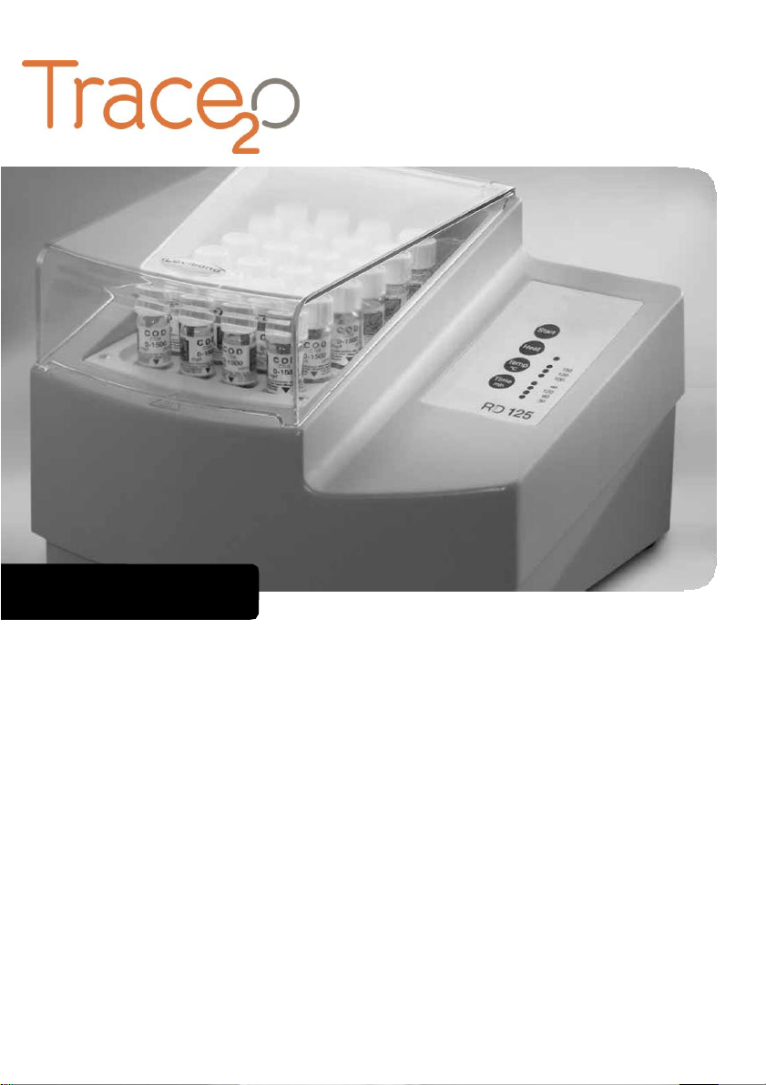
R
125
1.5 Buttons
Start key / Timer
Heat key
Temperature key
Time (interval) key
Heat LED
TemperatureLEDs
Time LEDs
1.6 Function of buttons
Start key (for timer): By pressing this key the work cycle will start with the
pre-selected values for temperature and time. At the end of the work cycle the
beeper will sound (Beeper, see p. 7) and the heater automatically switches off.
Heat key: By pressing this key (after switching the instrument on using the main on/
off switch see page 17) the reactor will heat up to the pre-selected temperature.
Temp key: By pressing this key the temperature is selected (scrolling). It is possible
to select between 100/120 and 150 °C. When a temperature is selected the
corresponding LED will light.
Time key: By pressing this key the time is selected (scrolling). It is possible to select
between: 30/60/120 min or
(infinite). When a time is selected the corresponding
LED will light.

7
2.
Work session
This section describes the use of the reactor for a standard application.
For further applications please refer to “Function schematics” (page 20).
After the unit is switched on (main switch, reverse side, position I) the keypad
automatically shows the last selected temperature and time span.
The corresponding LEDs are lighted.
After switching on the block heating does not commence automatically.
For heating up the unit press the “Heat” key.
After pressing this key the Heat LED is lighted.
Before and after pressing the “Heat” key temperature and time span still can be
changed.
During heating up the Temperature LED will light intermediately, when the selected
temperature is reached the Temperature LED is lighted permanently.
By pressing the “Start” key the timer starts the work cycles corresponding to the cho-
sen time span (indication by Time LED). Starting the work cycle the Time LED changes
from lighted to flashing.
When the work cycle ends Time LED and Temperature LED are lighted while the Heat
LED is off.
At the end of the work cycle the heater is switched off.
3.
Beeper
Select temperature or time:
short double beep
(two frequencies)
Switch heater on:
long beep (one frequency)
Switch heater off:
long beep (one frequency)
Temperature reaches the selected value:
8 x short beep
(two frequencies)
Start of countdown:
long beep (one frequency)
End of countdown:
16 x short beep
(two frequencies)
Pressing a key which is inactive
(at the moment):
short beep
(one frequency)
Malfunction:
Continuous beep (2 frequencies)
until the instruments is switched
off with the main switch (position “O”).
In this case the LED combination
according pages 12/13 allows a
failure defi

4.
Function
schematics
8
After switching on the instrument with the main on/off switch, the heater is not active. Press the HEAT-key for heating up (status 1).
After heating up to the selected temperature the timer starts after pressing START-key (status 3).
Status
Heat-LED
Temp.-LED
Time-LED
Heat-key
Start-key
Temp-/Time-
key
Heater
next possible
status
1. Waiting for
pressing HEAT-key
Off
last selected
temperature
last selected
time-span
Press: =>
Status 2
Ignore
Selection
possible
Off
After pressing
HEAT-key:
Status 2
2. Heating up
On
Flashing
On
Press =>
Status 1
Ignore
Selection
possible
Heating up
or Cooling
down
If selected
temperature is
reached:
Status 3
3. Waiting for
pressing START-key
On
On
On
Press =>
Status 1
Press for t =
30, 60, 120
Selection
possible
Temperature-
controlled for
stability of
the selected
temperature
After pressing
Start-key:
Status 4
(t
)
Ignore for
t=
If selected
temperature will
be changed:
Status 2
If temperature
to different to
selected one:
Status 2
4. Time: Count
down
On
On
Flashing
Press =>
Status 1
Ignore
Ignore
Stable
Temperature
End of count
down:
Status 1
Heat-LED
On:
Heating up or stabilizing selected temperature.
Temp.-LED
Off:
Flashing:
Heater is off
Selected temperature is not reached (heating up or cooling down)
Together with HEAT-LED On: Selected temperature is reached
Together with HEAT-LED Off: Indicates selected temperature without indication of the real temperature of the reactor
Time-LED
Flashing:
Count down function
On:
indication of selected time-span without count down function.

9
5. Maintenance
The unit is protected by a 4AT fuse. The position of the fuse holder is on the reverse
side of the unit under the main switch.
Should the fuse need changing, disconnect the unit from the power supply and open
the cover with a suitable tool to access the fuse.
6. Cleaning
No special maintenance is necessary apart from periodic cleaning of the unit.
Disconnect the unit from power supply and use a dust-free cloth with a
non flammable, non aggressive detergent to clean the unit.
ATTENTION:
If the reactor is contaminated by spillage of the tube contents or breakage of the
test tube, the disposal of waste (both glass and liquid) must be done according to the
instructions set out in the Material Safety Data Sheet (MSDS) (Chapter 6 and/or 13).
A contaminated aluminium block must be replaced prior to further use of the reactor.
The reactor should be sent to the manufacturer or an authorised service centre.
7.
Technical data
Powersupply
V/Hz
230 / 50-60 or
115 / 50-60 selectable
Power
W
550
Size
mm
248 x 219 x 171
Weight
kg
3.9
Construction materials
Housing: ABS
Protection grid: PPS
Lid:
PC
Block insert: PBT
Heating block: Aluminium
Holes in the
aluminium block
24 holes, ø 16.2 mm ± 0.2 mm
Selectable temperatures
°C
100 / 120 /150
Probe type
Pt100 A class
Temperature stability
°C
± 1
at the Pt100
Selectedtime
Heating up from
min
30 / 60 / 120 / continuous ()
(20°C --> 150°C)
min
12
Thermoregulation
Microprocessor
Protection
°C
at the Alublock for 190
against overheating
Beeper
dB
max. 88
Environmentalconditions(operation)
Temperature
°C
10 –40
Humidity
%
max. 85

10
8. Wiring diagramm

9.
Err
or
Code
(LED
indication)
11
No.
Error type
Possible reason(s)
Temp LED
LED30min
LED60min
LED120min
LED
Continuous beep
1
Power supply frequency
Frequency higher/lower
50Hz / 60Hz;
Mainboard faulty
on
off
off
off
on
yes
2
Safety feature reaction
Mainboard faulty
on
off
off
on
off
yes
3
ADC error
Mainboard faulty
on
off
off
on
on
yes
4
Wiring problem
internal connection
incomplete
on
off
on
off
off
yes
5
Heating problem
-
no power;
-
reactor power
-
probe problem
on
off
on
off
on
yes
6
T value underrange
Mainboard faulty
on
off
on
on
off
yes
7
T value overrange
Mainboard faulty
on
off
on
on
on
yes
8
Temperature too high
Probe connection faulty
Mainboard faulty
on
on
off
off
off
yes
9
Microprocessor failure
EMC-interference
100° on
120° off
150° on
on
off
on
off
no
10
Temperature on
mainboard too high
Unit overheated
on
on
on
off
off
yes

Table of contents
Other Trace2O Test Equipment manuals


Popular Test Equipment manuals by other brands

Kikusui
Kikusui HP01A-TOS Operation manual

Rubarth Apparate
Rubarth Apparate RUMED 4001 Operating and maintenance instructions

Greenlee
Greenlee 6700 instruction manual

Kemot
Kemot MIE2125 owner's manual

Gossen MetraWatt
Gossen MetraWatt SECUTEST ST BASE operating instructions

Wingmate
Wingmate BREATHALYSER user manual

Tinsley
Tinsley 58-FMC instruction manual

DH Instruments
DH Instruments E-DWT-10000-AF Operation and maintenance manual

Van Der Stahl
Van Der Stahl PTT-100 V operating instructions

Forch
Forch BT 12 V operating instructions

ATD Tools
ATD Tools ATD-5614 owner's manual

Hisense
Hisense HKF-D1EC Instructions for installation, use and maintenance manual


