SPX APV DELTA SDMU4 User manual

Read and understand this manual prior to
operating or servicing this product.
Operating Manual
DELTA SDMU4
Double Seal Change - Over Valve
with Membrane


1. General Terms 2
2. Safety Instructions 2
3. Mode of Operation 3
4. Auxiliary Equipment 4
5. Cleaning 4-5
6. Installation 6
6.1 Welding Instructions 6
7. Dimensions / Weights 7
8. Technical Data 8-9
9. Maintenance 10
10. Service Instructions 11-13
11. Installation of seat seal 14
12. Reconstruction of Actuator 15
13. Trouble Shooting 16
14. Spare Parts Lists
Double Seal Change-Over Valve with Diaphragm
SDMU 4
DN designRN 01.054.68
Tube design RN 01.054.68-1
Actuator RN 01.054.86
Leakage valveRN01.054.67-1
Table of Contents : Page :
1
Double Seal Change-Over Valve
with Diaphragm
Delta SDMU 4
Operating Manual Rev. 0
UK

This operating manual has to be read carefully and observed by
the competent operating and maintenance personnel.
We have to point out that we will not accept any liability for damage
or malfunctions resulting from the non-compliance with this
operating manual.
Descriptions and data given herein are subject to technical changes.
2. Safety Instructions
DANGER!
-The technical safety symbol draws your attention to important
directions for operating safety.You will find it wherever the activities
described are bearing risks of personal injury.
-Electric and pneumatic connections must be separated.
-Before any maintenance of the valve, the line system must be
depressurized.
- Do not reach into the open valve.
-Risk of injury by suddenly operating valve. In dismantled state
there is the risk of bruising at movable parts of the valve.
-Observe assembly instructions to ensure safe maintenance of
the valve.
-Attention!
With valve design NC (normally closed): Before releasing the
housing screws, the valve insert must be relieved by
controlling the actuator.
-The welded actuator is under spring load,do not open it by force.
1. General Terms
2
Double Seal Change-Over Valve
with Diaphragm
Delta SDMU 4
Operating Manual Rev. 0
UK

3. Mode of Operation
Double seal change-over valves with diaphragm DELTA SDMU4
were developed for the use in the brewing and beverage industries,
in the dairy and food industries as well as in chemical and
pharmaceutical applications.
The diaphragm valves offer optimum protection of the product in
hygienic and aseptic applications.
Product safety is achieved by the hermetic separation of the
product chambers to the outside (atmosphere) by means of a
flexible diaphragm.
- Leakage at the diaphragm is indicated via a leakage indication in
the yoke area.
The field of application of the DELTA SDMU4 comprises the safe
shut-off and change-over of line sections.The upper and middle
housing are separated from one another by two seat seals.
A leakage chamber is arranged between the seals, the leakage
chamber being forcible closed by the two leakage valves or
opened to the atmosphere.
Leakage at the seat seals of the upper valve shaft is discharged
via the leakage valves to the atmosphere and indicated.
- Operation by pneumatic actuator with air connection.
The actuator is generally mounted normally closed (NC).
- The inner parts of the actuator are maitenance-free.
- To avoid pressure hammers,the valve is to be closed against the
flow direction of the fluid.
- As standard design a control unit DELTA CU21N with NOT element
is installed on top of the actuator for the pneumatic control of the
valve.The NOT element fulfills the task to increase the closing
forces of the closed valve.
- The yellow luminous diodes in the control unit indicate the position
of the valve shaft.
- Observe assembly instructions to ensure safe maintenance of
the valve.
3
position
indicator
Control Unit
Delta CU 21N
actuator
housing
housing cover
housing
yoke
leakage
valve
leakage
indication
Double Seal Change-Over Valve
with Diaphragm
Delta SDMU 4
Operating Manual Rev. 0
UK

4. Auxiliary Equipment
-Valve position indication
A proximity switch holder (PSH) for the valve position indication can
be installed direct on the actuator.
With SDMU4 valves being equipped with a PSH it must be observed
that the max.closing pressure is reduced compared with the valve
design being equipped with the control unit DELTA CU21N.
(see table,item 8)
Proximity switches to signal the limit position of the valve seat can be
installed at the proximity switch holder (PSH) if requested.
We recommend to use one of our APV standard types:
operating distance: 5 mm / diameter: 11 mm.
If the customer decides for a valve position indication other than
APV type, we cannot take over any guarantee for a faultless function.
- Field bus
The direct assembly of an intelligent control unit DELTA CU21VN,
Valve-Net with NOT element (field bus technology) is also possible.
5. Cleaning
For the cleaning of SDMU4 valves one has to distinguish between
two areas.
- The flow chambers
The passages of the valve are cleaned by the cleaning liquid during
the cleaning of the connected pipelines.
- The leakage chamber
The cleaning of the leakage chamber is effected via the leakage
valves.The cleaning liquid is supplied via one leakage valve and
discharged to the atmosphere via the second leakage valve.
The restraint passage of the cleaning liquid provides for a perfect
cleaning of the whole leakage chamber.
Under normal conditions,15 valves DN 25/1T - 100/4T can be
cleaned via one spray distribution line DN 25.
4
Double Seal Change-Over Valve
with Diaphragm
Delta SDMU 4
Operating Manual Rev. 0
UK

5
5. Cleaning
- Depending on the pressure ratio, cleaning temperatures and the
degree of soiling,different times have to be adjusted.
- Flushing quantity per CIP spraying about 1,2 ltr / 10 s.
- Cleaning pressure at CIP cleaning connection min.2 bar
max. 5 bar.
Cleaning of the leakage chamber
via the leakage valves.
Recommendation for cleaning times with usual operating conditions and
CIP liquids.
cleaning step CIP spraying
pre-flushing 3 x 10 sec.
caustic flushing 80 oC 3 x 10 sec.
intermediate flushing 2 x 10 sec.
acid flushing 3 x 10 sec.
subsequent flushing 2 x 10 sec.
in out
Double Seal Change-Over Valve
with Diaphragm
Delta SDMU 4
Operating Manual Rev. 0
UK

6
6. Installation
- Installation has to be done in such a way that fluids can drain off
the valve housing and is preferably to be realized in vertical position.
-Attention: Observe welding instructions.
6.1 Welding Instructions
SDMU4
- Before welding of the valve, the valve insert must be dismantled from
the housing.The lower housing seal has to be removed as well. See
to a careful handling to avoid damage to the parts.
- Welding may only be carried out by certified welders (EN 287-1).
(seam quality EN 25817 "B")
- The welding of the valve housings must be effected in such a way
that deformation strain cannot be transfered from the outside to the
valve body.
- The preparation of the weld seam up to 3 mm thickness must be
carried out in butt manner as a square butt joint without air.
(Consider shrinkage!)
- TIG orbital welding should be aimed at!
- After welding of the valve housings or of the mating flanges and after
work at the pipelines, the corresponding parts of the installation or
pipelines must be cleaned from welding residues and soiling.If these
cleaning instructions are not observed,welding residues and dirt
particles can settle in the valve and cause damage.
- Any damage resulting from the nonobservance of these welding
instructions is not subject to our guarantee.
Double Seal Change-Over Valve
with Diaphragm
Delta SDMU 4
Operating Manual Rev. 0
UK
7
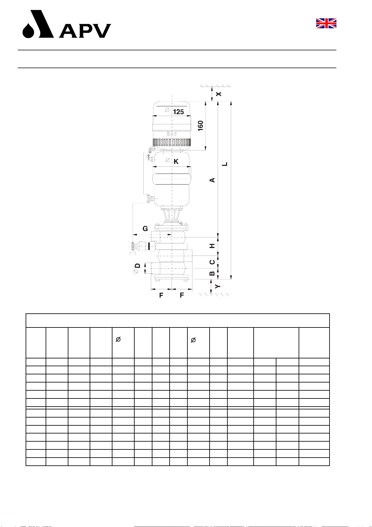
7. Dimensions / Weights
dimensions in mm
DN A B C D F G H K L stro ke
in
mm
install.
dimensions
in mm
Y X
weight
in Kg
SDM U 4
25 29,532 26,050
40
446,2
37,544 38,067 130
63,5
126
591,2
10 300 200
50
453,5
43,556 50,072 132
75,5
126
630,5
10 330 200
65 52,074 66,085
80 59,591 81,098
Tube
1T 27,828,622,650
1,5T
444,8
36,140,834,967 130
60,4
126
581,9
10 300 200
2T
451,9
44,453,847,672 132
73,1
126
623,2
10 330 200
2,5T 49,068,060,385
3T 55,180,972,990
Double Seal Change-Over Valve
with Diaphragm
Delta SDMU 4
Operating Manual Rev. 0
UK

8
kvs values forSDM U4
valves in (m 3 /h )
SDM U 45,
SDM U 46 SDM U 45,
SDM U 46
DN
25
40
38 38
50
70 70
65
80
100
Tube
1T
1,5T
38 38
2T
70 70
2,5T
3T
4T
8. Technical Data
Product-wetted parts: 316 L, 1.4404
Other parts: 1.4301
Seals:
Standard: EPDM
Option: HNBR
Membrane: TFM / EPDM
Actuators: 1.4301
Max. operating temperature: 140 °C EPDM, HNBR
Sterilization temperature: up to 150 °C EPDM
(short-term) 140 °C HNBR
Air connection (for hose): 6 x 1 mm
Max. pneumatic air pressure: 8 bar
Min. pneumatic air pressure: 6 bar
(Use dry and clean pneumatic air, only.)
Closing times for double seal valves SDMU4
The opening and closing times can be fixed by adjustment of the
throttling screw at the solenoid valve.
Double Seal Change-Over Valve
with Diaphragm
Delta SDMU 4
Operating Manual Rev. 0
UK
9
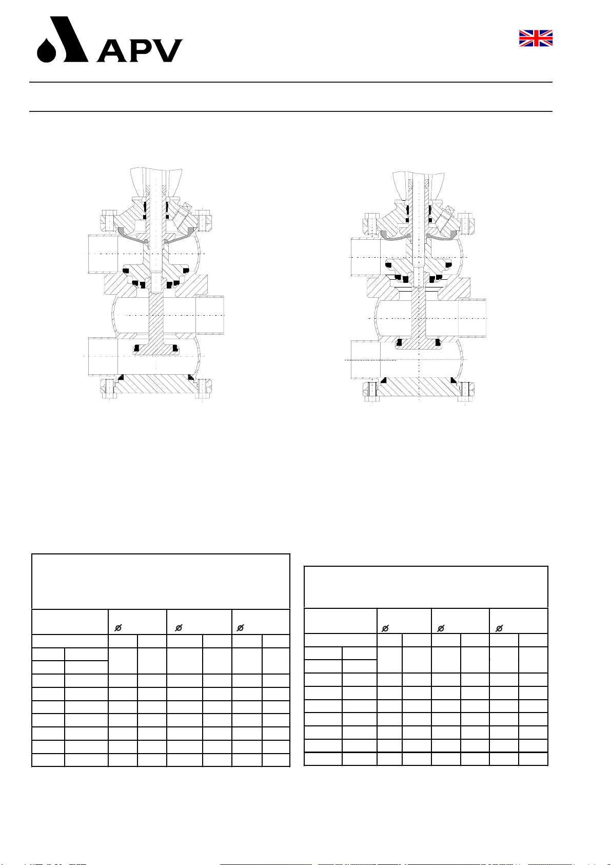
8. Technical Data
Operating position: A/ NC (normally closed) Operating position: B / valve controlled
Note: In case of compressed air failure the max.product pressure has to be as
indicated in tab. 1.Consider these figures for the design of the valves.
- Due to the seal technology, the max. product pressure is limited to 17,6 bar.
- The product pressures for the valve position B as indicated in tables 1 and 2
are standard values at a standard compressed air pressure of 5,4 bar.
DELTA SDMU4m ax.productpressures in (bar)
valve norm ally closed withoutNOT elem ent
orwith com pressed air failure
actuator
74 mm actuator
110 mm actuator
165 mm
valve position A B A B A B
DN Tube
25 1T
40 1,5T 12,917,6
50 2T 8,110,5
65 2,5T
3T
80
DELTA SDMU4m ax.productpressures in (bar)
valve norm ally closed and NOT elem ent
actuator
74 mm actuator
110 mm actautor
165 mm
valve position A B A B A B
DN Tube
25 1T
40 1,5T 17,617,6
50 2T 17,610,5
65 2,5T
3T
80
Table 1 Table 2
Double Seal Change-Over Valve
with Diaphragm
Delta SDMU 4
Operating Manual Rev. 0
UK

10
- The maintenance intervals depend on the corresponding
application and are to be determined by the operator himself
carrying out temporary checks.
- Required tools:
- 1 x spanner SW13
- 1 x spanner SW17
- 1 x spanner SW19
- 1 x hexagon socket screw key 6 mm.
- Exchange of seals is done according to assembly instructions.
- All seals must be provided with a thin layer of grease before their
installation.
-The diaphragm must be provided with a thin layer of grease
from the product-averted side.
Recommendation:
APV food-grade-grease for EPDM and HNBR
(0,75 kg/tin - ref.-No. 000 70-01-019/93)
(60 g/tube - ref.-No. 000 70-01-018/93)
! No matter what type of application,use only those greases
being suited for the respective seal material !
9. Maintenance
Double Seal Change-Over Valve
with Diaphragm
Delta SDMU 4
Operating Manual Rev. 0
UK

11
10. Service Instructions
Delta SDMU 4
The item numbers refer to the corresponding spare parts lists
Tube: RN 01.054.68-1
I. Dismantling from the line system
a. Shut off the line pressure and discharge the lines if possible.
Release the connections with the leakage valves.
b. With design NC: control actuator with air.
Do not reach for movable parts!
Risk of injury.
c. With CU design (Control Unit):
-Lift the control unit by turning the safety ring,remove the
operating cam and the hexagon nut (27) by holding against the
centering disc (26). Remove the centering disc.
With PSH design (Proximity Switch Holder):
-Remove the cover (29) from the actuator (24) and release the
operating cam (31) by holding against the centering disc (26).
Remove the centering disc.
d. Release the hexagon screws (18) and remove the housing cover.
e. Pull the lower valve shaft (2) to the bottom out of the housing.
f. With NO design: Shut off air.
With NC design: Control with air.
g. Remove the hexagon screws (14) from the yoke flange (11).
h. Lift the actuator (24) with yoke (11) to the top and out of the
housing.The diaghram (7), the upper shaft M4 (8) and the middle
shaft SDMU4 (6) are accessible.
29
26
26
31
8
7
6
2
24
11
14
18
27
operating cam
Double Seal Change-Over Valve
with Diaphragm
Delta SDMU 4
Operating Manual Rev. 0
UK

12
10. Service Instructions
II. Dismantling of seals (service)
a. Pull off the O-ring (16) from the housing cover.
b. Remove the seat seal (3) in the lower valve shaft (2).
c. Remove the seat seals (4, 5, 15) in the middle valve
shaft SDMU4 (6).
d. Release the yoke (11) from the actuator (24).
e. Take the O-ring (9) and guide bush (10) out of the yoke (11).
III. Installation of seals and assembly of the valve
The item numbers refer to the spare parts drawings
Tube design: RN 01.054.68-1
a. Insert the guide bush (10) and the O-ring (9) into the yoke (11).
(Provide the seals with a thin layer of grease.)
b. Screw the actuator (24) and the yoke (11) together.
c. Provide the seat seals with a thin layer of grease before their
installation.
-Use the APV assembly tool, see chapt. 11, for the installation of
the lower seat seal (3).
-For the installation of the seat seals (4, 5) into the seal grooves,
the seals have to be inserted by a rounded screw driver.After the
installation, the seals have to be vented between the groove wall
and seal by the tool.See to the correct position and an even fit of
the seals.
d. Insert the seat seal (15).
e. Place the middle shaft SDMU4 (6) from the top centrally in the
valve housing.
f. Provide the product-averted side of the diaphragm with a thin layer
of grease. Place the diaphragm (7) on the upper shaft M4 (8) and
insert it into the yoke (11).
e. With valve design NC: Control the actuator with air.
Press the complete unit (actuator, yoke,upper shaft M4 with
diaphragm) into the housing and tighten the hexagon screws (14)
crosswise.
11
910
24
11
8
7
6
5
4
3
15
Double Seal Change-Over Valve
with Diaphragm
Delta SDMU 4
Operating Manual Rev. 0
UK

13
10. Service Instructions
III. Installation of seals and assembly of the valve
f. Push the lower shaft (2) from the bottom into the housing.
Place the centering disc (26) and tighten the hexagon nut (27)
with CU design or the operating cam (31) with PSH design.
Hold against the centering disc for this purpose.
Tightening moment of Md = 40 Nm.
Shut off control air !!!
g. Lightly grease the O-ring (16) and insert it into the groove of the
housing cover (17). Fix the housing cover by means of the
hexagon screws (18).
h. With CU design:
Place the control unit and fix it accordingly.
With PSH design:
Place the proximity switch holder and fix it accordingly.
Insert the proximity switches and fix them.
-Readjust the proximity switches if necessary.
i. Connect the leakage valves.
j. Connect the compressed air supply.
IV. Maintenance of leakage valves
The item numbers refer to the corresponding spare parts list.
Leakage valves RN: 01.054.67.
a. Pull off the compressed air hoses at the two leakage valves.
b. Shut off and drain off the CIP supply line.
c. Remove the CIP supply and drain lines from the leakage valves.
d. Release the inner hexagon screw and the bracket.
e. Unscrew the threaded cap (3), pull off the piston (2) and the
spring (6).
f. Dismantle all seals (5, 7, 8).
g. Assembly is done in reverse order.
leakage valve
27
26
2
17
16
Double Seal Change-Over Valve
with Diaphragm
Delta SDMU 4
Operating Manual Rev. 0
UK
14
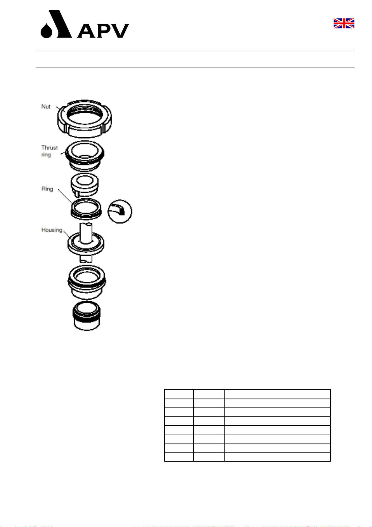
11. Assembly tool for seat seal
The assembly tool consists of:
- nut
-thrust ring
-ring with venting plug
-housing
Installation of the seat seal in the valve shaft
1. Insert the valve shaft into the housing in such a manner that
the seal groove is in the valve housing.
2. Clamp the shaft in the housing by the threaded bolt.
3. Lightly grease the seat seal.
Use food-grade special grease for this purpose.
Pull the seal onto the ring with venting plug until it stops.
4. Insert the ring with the seat seal into the housing and press it down
until it stops.
5. Insert the thrust ring into the housing.Screw on the nut and tighten it
by a hook spanner until it stops.
6. Release the nut. Pull the ring and the thrust piece out of the housing.
7. Take the housing out of the vise, open the slewable brackets and take
the shaft out of the housing. Check the correct fit of the seat seal.
Assem bly toolforthe lowerseatseal
DN Tube ref.-No.
25 1T 000-51-13-110/17
40 1,5T 000-51-13-111/17
50 2T 000-51-13-112/17
65 2,5T 000-51-13-113/17
3T 000-51-13-121/17
80 000-51-13-114/17
100 4T 000-51-13-115/17
Double Seal Change-Over Valve
with Diaphragm
Delta SDMU 4
Operating Manual Rev. 0
UK

15
I. Maintenance of the actuator
The item numbers refer to the spare parts drawing.
Actuator:RN 01.054.86
a. Remove the control unit or proximity switch holder.
(see service instructions, chapt. 10.1.-a-h.)
b. Remove the inner hexagon screw from the adapter (25) of the
control unit.
c. Screw off the two seal screws (1) by holding against the actuator
by a strap wrench.Remove the O-rings (3) and the V-seals (2).
II. Installation of seals and assembly of the actuator
a. Install the lightly greased O-rings (3) and the V-seal (2) in the seal
screw (1).
See to the correct direction of the V-seal.
b. Push the seal screws over the piston rod at both sides of the
actuator and tighten them.
c. Fix the adapter of the control unit.
Attention: See to the position of the adapter.
Attention: Consider the required valve design
NC = normally closed
NO = normally open
during the assembly of the actuator.
By turning the actuator by 180°, an optional design NC or NO
can be determined.
d. Fix the air hoses.
e. The assembly of the valve is done in reverse order.
12. Actuator
Double Seal Change-Over Valve
with Diaphragm
Delta SDMU 4
Operating Manual Rev. 0
UK
Table of contents
Other SPX Industrial Equipment manuals

SPX
SPX Marley Geareducer 2800 Series User manual

SPX
SPX Waukesha Cherry-Burrell Votator II User manual

SPX
SPX Marley Geareducer 32.2 Series User manual

SPX
SPX Power Team HNS150A User manual

SPX
SPX Hankison Trip-L-Trap 505 User manual

SPX
SPX CUES ACCUPOINT MS611 User manual

SPX
SPX RD1000 User manual

SPX
SPX APV ParaFlow User manual

SPX
SPX OTC PRO-CRUSH 1896 User manual

SPX
SPX MARLEY Geareducer 2700 Series User manual


