SPX RD1000 User manual

COMPANY CONFIDENTIAL
System Assembly
Open the main box; remove the Accessory Box, Cart Base and
Sensor Box. Open each box and lay out all the components.
RD1000 Training Course
Version 1 19

COMPANY CONFIDENTIAL
Using the Display Unit
The Display Unit has 8 buttons numbered 1 to 8, larger Pause and
Camera buttons as well as buttons to increase and decrease the
screen Contrast and Brightness.
Turn on the system by pressing any button on front of the Display Unit.
Both red lights will illuminate and after few seconds, the splash screen
and menu will appear.
The menu option on the screen above
the button indicates its function.
RD1000 Training Course
Version 1 20

COMPANY CONFIDENTIAL
Using the Display Unit
To operate the system:
a) The first screen displayed when the system is powered on is the Systems Settings
Screen. It has options to start scanning or change settings such as language,
measurement units, date and time.
b) To start scanning, press Scan to display the Scanning Screen. When the scale
appears on the right side of the screen, push the cart. The data image scrolls across
the screen from the right.
c) Stop and back up to see the Locating Screen to mark the exact position of a target on
the ground and to access the menu to estimate its depth.
d) When you push the cart forward again and reach the point where you originally stopped
and backed up, the system will automatically start scanning again. Or press Clear
Screen to start fresh.
e) At any time press the Pause button to change Depth, Color, Gain etc. using the Image
Settings Screen then press Scan (or Pause again) to continue.
If the Display Unit has Compact Flash disk, pressing the Camera button saves the current
screen image to the Compact Flash. Later, transfer images to a PC for re-plotting and
printing.
RD1000 Training Course
Version 1 21

COMPANY CONFIDENTIAL
System Settings Screen
Scan
Press the Scan button to start scanning.
Language
Select the language for the menus.
Current options are English or Icons.
Units
Units for the Position Axis, Depth Axis
and Depth Indicator can be either
Meters or Feet.
RD1000 Training Course
Version 1 22

COMPANY CONFIDENTIAL
System Settings Screen
RD1000 Training Course
Version 1 23

COMPANY CONFIDENTIAL
System Settings Screen
Scale
The Scale button toggles to four
different Scale options:
1) Lines means Depth Lines are
plotted on the data image to assist
with determining the depth of
targets.
RD1000 Training Course
Version 1 24

COMPANY CONFIDENTIAL
System Settings Screen
2) Text means Depth Values are
plotted in the center of the data
image every 8 metres or 26 feet.
RD1000 Training Course
Version 1 25

COMPANY CONFIDENTIAL
System Settings Screen
3) Both means both Depth Lines
and Values are plotted on the
data image.
4) Off means no Depth Lines and
Values are plotted on the data
image.
RD1000 Training Course
Version 1 26

COMPANY CONFIDENTIAL
System Settings Screen
Date
Opens the Date Screen to change the current date. Images are saved
with this date.
Time
Opens the Time Screen to change the current date. Images are saved
with this time.
Power Off
Opens a sub-menu to confirm powering off the system. There is also
an option to restore the system to factory default settings.
System Information
The top of the Systems Setting Screen displays the serial number of the
GPR sensor, the software version number, the GPR Sensor frequency
(in MHz) and the current battery voltage.
RD1000 Training Course
Version 1 27

COMPANY CONFIDENTIAL
Scanning Screen
After pressing the Scan button, wait a few
seconds for the vertical depth scale to
appear on the right side of the screen, and
then push the Cart forward.
A cross-sectional image of the ground scrolls
onto the screen from the right to left. The
position is displayed on the horizontal axis at
the top while the depth is displayed on the
vertical axis. The position and depth axes
units are meters or feet depending on the
units set in the Systems Setting Screen.
If the Scale or Both option is selected,
horizontal depth lines appear on the image to
assist with determining the depth of targets.
RD1000 Training Course
Version 1 28

COMPANY CONFIDENTIAL
Scanning Screen
Approximately 16 meters or 50 feet of data is displayed on one screen. If the
survey line exceeds this distance the image will scroll off the left side of the
screen.
To save the current screen image to file, press the Camera button on the
Display Unit. The image number appears on the bottom of the screen with a
message to press any button to continue.
A message will appear on the screen if there is no Compact Flash card in the
Display Unit. Images are only saved when a card is present.
Pressing any of the number buttons on the Display Unit marked 1 to 8 while
scanning adds a numbered marker at the current position.
Pressing the Pause button opens the Image Settings Screen to change the
current Color Palette, Depth, Filter and Gain.
Stopping and pulling the cart backwards along the same path automatically
opens the Locating Screen used to pinpoint the position and depth of a target.
RD1000 Training Course
Version 1 29

COMPANY CONFIDENTIAL
Locating Screen
The Locating Screen is accessed by stopping and pulling the cart
backwards while scanning. The cursor moves over the image and menu
options appear at the bottom of the screen.
Locating Cursor
The Cursor consists of 3 parts:
Position Indicator
Vertical cross-hair is tied to the odometer and
corresponds to the location at the center of the
GPR sensor. As the cart is pulled backwards,
the Position Indicator moves to indicate the
current location of the cart in the image.
Depth Indicator
Horizontal cross-hair found at the peak of the soil type indicator arch indicating
the depth. The Depth Indicator moves up or down using the Arch Up and
Down buttons.
RD1000 Training Course
Version 1 30

COMPANY CONFIDENTIAL
Locating Screen
Indicator Arch
Idealized representation of a typical pipe-like target response observed on the
GPR image. The width of the arch is controlled by soil type setting. The soil
type setting is changed using the Arch buttons. Increasing the soil type makes
the indicator arch wider while decreasing the soil type makes it narrower.
Soil Type
To obtain an accurate depth axis and depth estimations of targets in the GPR
image, a Soil Type Calibration must be performed. Soil Type Calibration can be
done 3 ways:
1) Matching the shape of a target arch,
2) Using a target at a known depth, or,
3) Using the moisture level of the soil.
RD1000 Training Course
Version 1 31

COMPANY CONFIDENTIAL
Locating Screen
Matching a Target Arch
Targets like pipes, cables, buried artefacts, tree roots and rocks generate
arch-shaped responses on the GPR image.
Arches occur because GPR energy does not travel into the ground as a
pencil-thin beam but more like a 3D cone. Reflections can appear on the record
even though the object is not directly below the GPR sensor. Thus, the GPR
sensor “sees” the pipe before and after going over top of it and forms an
arch-shaped response on the image.
Cross long, linear targets like pipes or cables at a 90 degree angle to produce a
target arch suitable for the soil type calibration. The depth estimation of a target
will be incorrect if the soil type calibration is done on a target arch produced at
an oblique angle (smaller that 90 degrees).
RD1000 Training Course
Version 1 32

COMPANY CONFIDENTIAL
Locating Screen
Estimating target depth
RD1000 Training Course
Version 1 33

COMPANY CONFIDENTIAL
Locating Screen
To determine the Soil Type using
a Target Arch:
With a target arch visible on the image,
back the cart up until the Position Indicator
is centered on the target arch in the GPR
image; preferably one with long tails
because this provides the most accurate
soil type calibration.
RD1000 Training Course
Version 1 34

COMPANY CONFIDENTIAL
Locating Screen
As you slow down and stop, the Indicator Arch will appear on the data image.
RD1000 Training Course
Version 1 35

COMPANY CONFIDENTIAL
Locating Screen
Use the Up and Down Arrows
to move the Indicator Arch
shallower or deeper in the GPR
image respectively, until it lies
overtop of the target arch.
RD1000 Training Course
Version 1 36

COMPANY CONFIDENTIAL
Locating Screen
Press the Soil Type button and toggle through the five different soil types to find
the one that roughly fits the shape of the Indicator Arch to the shape of the
Target Arch.
Use the Wide and Narrow Arch buttons to change the shape of the Indicator
Arch to match the shape of the Target Arch on the GPR image. The depth of
the target is indicated on the bottom left.
Press the Apply button to save the Soil Type and update the Depth Axis on the
Scanning Screen. The Depth axis can now be used to estimate the depth of
targets while scanning in the area.
RD1000 Training Course
Version 1 37

COMPANY CONFIDENTIAL
Locating Screen
Target at Known Depth
If there are no suitable arches visible in the image to perform the Target Arch
Matching described above, there may be a target of known depth in the area
being scanned.
To determine the Soil Type using a target at known depth:
1) With the target response visible on the image, use the Up and Down Arrows
to move the Depth Indicator (and Indicator Arch) until it lies on top of the
GPR response of the known target.
2) Use the Wide and Narrow Arch buttons to change the shape of the Indicator
Arch until the depth of the target, displayed in red above the menu, is correct.
3) Once the depth is matched, save the Soil Type value by pressing the Save
button.
RD1000 Training Course
Version 1 38
Table of contents
Other SPX Industrial Equipment manuals
SPX
SPX APV DELTA SDMU4 User manual
SPX
SPX CUES ACCUPOINT MS611 User manual
SPX
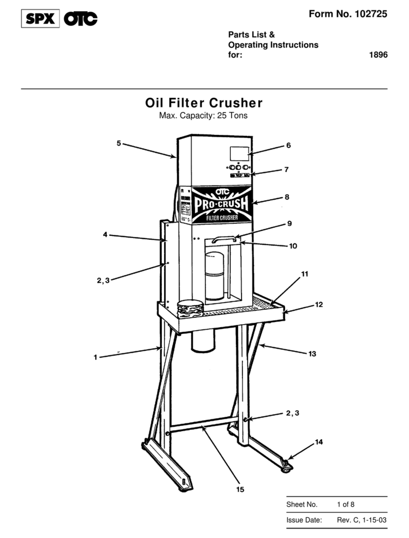
SPX OTC PRO-CRUSH 1896 User manual
SPX
SPX Hankison Trip-L-Trap 505 User manual
SPX
SPX MARLEY Geareducer 2700 Series User manual
SPX
SPX APV Cavitator User manual

SPX
SPX Waukesha Cherry-Burrell Votator II User manual
SPX
SPX Power Team HNS150A User manual
SPX
SPX Marley Geareducer 34.4 Series User manual
SPX
SPX Marley Geareducer 2800 Series User manual

