manuals.online logo
Brands
  1. Home
  2. •
  3. Brands
  4. •
  5. SSS Siedle
  6. •
  7. Gateway
  8. •
  9. SSS Siedle SG 650-0 Installation and operation manual

SSS Siedle SG 650-0 Installation and operation manual

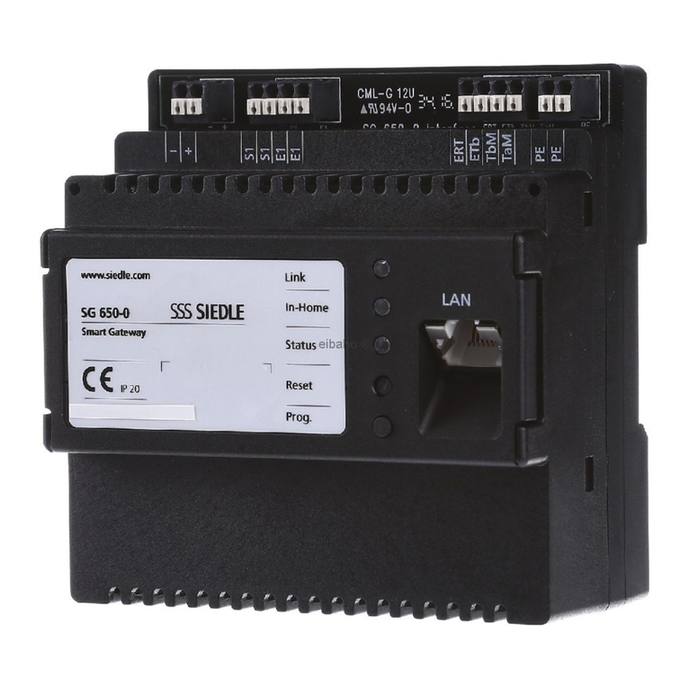
SG650-0
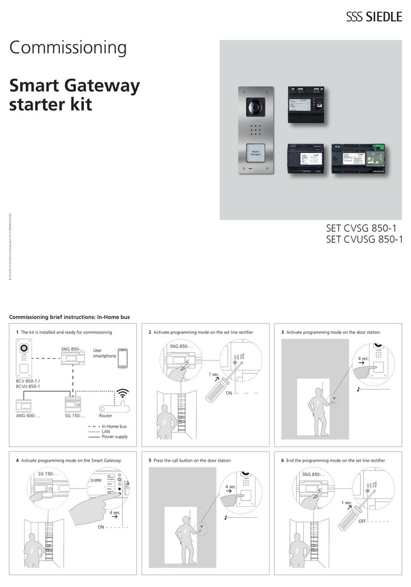
Commissioning instruction
Smart Gateway
2
Contents
Safety remarks
Observe the safety instructions. 4
Electrical voltage 4
Servicing 4
Protect your property! 4
Protect your network! 4
Legal notice 4
Product registration 4
Automatic logout 4
Overview
System overview 5
Commissioning sequence 6
Bus addresses in the
In-Home bus 7
Functions applicable across
individual lines 7
Connection
of bus and IP address 7
Example – Single line system 8
Example – Multiple line system 8
System limits 8
Preparation
Menu structure User interface 10
Information on programming 11
Programming with PC and
Bus programming software
BPS650-… 11
Manual programming,
also called „Teach-In“ 11
Programming and
functional scope 11
Basic functions 11
Supplementary functions 11
Direct LAN connection 12
Indirect LAN connection with
active DHCP server 12
Indirect LAN connection with
inactive DHCP server 13
Commissioning
requirements
Commissioning requirements 14
Fullling commissioning
requirements 15
Step-by-step through the
commissioning process 15
Register product 15
Downloading and installing the
bus programming software 15
Commissioning
Manual programming 16
Programming with PC and
Bus programming software
BPS650-… 17
Login on the Smart Gateway 17
Performing a system update 17
Information on the
Smart Gateway update 17
Change user prole / password 18
Setting the date and time 18
Check/change the
network settings 18
Setting video memory/door call 18
Import In-Home bus
conguration 19
Creating IP users 19
Deleting IP users 19
Creating IP groups 19
Storey call –
Dening IP users/IP group 19
Registering IP users 19
Siedle app for Smart Gateway 20
Bus software in-house
telephone 20
Carry out a function check 20
Optional
commissioning steps
Reserving bus addresses 21
Import user licences 21
Logging 22
Backing up/
Restoring the system 22
Resetting the system 23
Restarting the SmartGateway 23
IP address and password reset 23
These commissioning instructions
supplement/are supplemented
by:
• Product Information
SmartGatewaySG 650-0
• System Manual In-Home bus:
Video
The relevant current edition is
located in the download area on
www.siedle.com
Subject to printing errors.
We reserve modications depending
on technical improvements.
Index 24
3
Quick overview – Commissioning
Observe the safety instructions. 4
Selecting the bus programming mode
(manual or bus programming software) 11
Checking, selecting and preparing the network connection 12
Fullling commissioning requirements 14, 15
Register product 15
Downloading and installing the bus programming software 15
Programming the Smart Gateway in the In-Home bus and
exporting the conguration 16, 17
Login on the Smart Gateway 17
Performing a system update 17
Change user prole / password 18
Setting the date and time 18
Check/change the network settings 18
Setting video memory/door call 18
Import In-Home bus conguration 19
Creating IP users / Creating IP groups 19
Storey call – Dening IP users/IP group 19
Registering IP users 19
Carry out a function check 20
4
Safety remarks
Observe the safety instructions.
Read and observe the safety instruc-
tions and content of the following
supplied documents before using
Smart Gateway for the rst time:
• Product information sheet
• Commissioning instruction
• System Manual In-Home bus:
Video
Explain the content of the safety
instructions and dangers inherent in
using technically complex products
to children and those requiring
assistance in a way that is easily
understandable.
Electrical voltage
Mounting, installation and servicing
work on electrical devices may only
be performed by a suitably qualied
electrician.
Servicing
Statutory warranty conditions apply.
If the device requires servicing,
contact your specialist dealer or elec-
trical installer.
Customer service in the Furtwangen
factory
+49 7723 63-434
Protect your property!
Lock front doors or apartment doors
during the daytime if there is nobody
home. Unlocked doors allow thieves/
burglars to gain easy access to your
property.
The Siedle app for Smart Gateway
can be used from any location as a
door release. Keep smartphones/tab-
lets on which the Siedle app is acti-
vated safe from theft. Protect these
devices against unauthorized usage
with a code / password. Always use
the latest protection mechanisms
available for your smartphone/tablet.
Protect your network!
Only use up-to-date components
and terminals in the network in
line with the latest state of the art.
Regularly update the operating sys-
tems of all components and termi-
nals. Exchange obsolete components
and terminals for up-to-date models.
Use professional protective software
(antivirus, rewall,…) in all terminals.
Issue secure passwords. Secure your
network with the highest security
standards available in the network.
Protect your network against unau-
thorized attack from inside and
outside.
If you are no longer using an smart-
phone/tablet or PC/laptop with
the Siedle app for Smart Gateway
Mini or bus software in-house tele-
phone installed, either temporarily
or over longer periods (repair, sale,
exchange), uninstall the app/soft-
ware from this device. Never hand
over an smartphone/tablet with an
operable app/software to a third
person!
Delete the affected IP user from the
Smart Gateway. This ensures that
the affected IP user no longer has
access to the door station.
In case of emergency:
• Pull the network cable out of
the LAN connection of the Smart
Gateway
or
• Deactivate the WLAN of the WLAN
router
• Block any existing external access
to the LAN network.
Legal notice
Photographs of individuals taken
without their knowledge may not be
published or stored in publicly acces-
sible video memory facilities.
Individuals who have been photo-
graphed without their knowledge
are entitled to request that pictures
be deleted based on the right of per-
sons to their own likeness.
Never store pictures of persons you
do not know in social networks or
send them by email to others/public
groups. This will infringe their per-
sonal rights.
If stored images are used as part of
private / criminal law proceedings or
in a police investigation, this requires
prior clarication with a lawyer or
the responsible police authority.
The legally admissible operation and
installation of this device and all its
system components (hardware and
software) are the responsibility of
the user and not of the device man-
ufacturer.
Product registration
Siedle software is continuously
updated and further developed. To
ensure that you make use of all the
product benets and to obtain reg-
ular future updates, we recommend
that you register your product in the
My Siedle Service Portal:
www.siedle.com/mysiedle
Automatic logout
For security reasons, the Smart
Gateway logs out of any session
with a logged-in user if no entry has
been made in the user interface for
10 minutes. In order to prevent the
session time from being extended
articially due to the changes to the
time settings, after every change of
time setting, an automatic system
logout takes place.
5
System overview
Simplied layout showing arrange-
ment of the Smart Gateway, Bus
software in-house telephone,
Siedle app for Smart Gateway
and the installed Siedle intercom
in the overall system.
Possible IP clients:
• Siedle app for Smart Gateway
• Bus software in-house telephone
Integrable networking
components:
• IP cameras
BVNG 650-...
Siedle intercom system
building installation
Door station
PC/Laptop with
installed Bus
software in-house
telephone
BSHT650-0
WLAN
Internet
Router/Switch
DHCP = ON
SG650-…
Mobile phone
with installed
Siedle app for
Smart Gateway
WLAN
Internet
SG650-…
IP Camera
In-Home bus
LAN
ERT
ETb
TbM
S1
S1
–
+
E1
E1
PE
PE
TaM
0000000000000
SmartGateway
SG 650-0
IP20
www.siedle.com Link
In-Home
Status
Reset
Prog.
ERT
ETb
TbM
S1
S1
–
+
E1
E1
PE
PE
TaM
0000000000000
SmartGateway
SG 650-0
IP20
www.siedle.com Link
In-Home
Status
Reset
Prog.
IP network 2
IP network 1
Mobile phone
with installed
Siedle app for
Smart Gateway
Router/Switch
DHCP = ON
PC/Laptop with
installed Bus
software in-house
telephone
BSHT650-0
Overview
6
Overview
Commissioning sequence
Mount the Smart Gateway, connect to the In-Home bus /
IP network and switch on.
See Product Information/
System Manual
Programming the In-Home bus
(manually or using the bus programming software). 11, 16
Optionally: Obtain additional In-Home bus addresses
and extend the In-Home bus programming. 21
Export the In-Home bus conguration from the bus programming software. 17
Import the In-Home bus conguration, congure the Smart Gateway. 17
Install the software (Siedle app, bus software in-house telephone) on the terminals
(PC/laptop/tablet/mobile phone) and log in at the Smart Gateway. 20
Carry out a complete function test and hand over the
documentation/les to the customer. 20
7
Bus addresses in the In-Home bus
As a one-line bus system, the
In-Home bus is restricted to a max-
imum of 31 bus addresses (bus
users). A bus video line rectier is
required for the one-line system.
If more than 31 bus addresses (bus
users) are required, up to 15 bus
lines can be coupled with each other
in the multiple line bus system.
For each bus line, you require a ded-
icated bus video line rectier (e.g. 2
bus lines => 62 bus addresses (bus
users) => 2 bus video line rectiers).
Irrespective of whether you have a
one or multiple line bus system, the
SmartGateway can only reserve the
free bus addresses in the bus line
in which it is operated. Bus address
reservation across different lines is
not possible.
If you need all 31 bus addresses for
operation in the Smart Gateway,
the rest of the components must be
operated in the In-Home bus (door
station, indoor call stations) at an
additional bus line. In such a case,
you will be operating a multiple line
bus system and you will require 2
bus video line rectiers for this.
Please note that within a bus line,
the maximum functional scope is
available which has been made
available by the relevant program-
ming mode. In cross-line operation
between 2 different bus lines, indi-
vidual functions are not available for
technical reasons.
Functions applicable across indi-
vidual lines
Door calls, selective door dialling and
switching and control functions can
also be used across individual lines.
Internal speech communication and
call forwarding between users is only
possible within a line.
Connection of bus and IP address
If you are operating the Siedle
intercom and the Smart Gateway
in the single-line bus system, each
component of the intercom is
assigned the technically stipulated
number of bus addresses
(indoor station = 1 bus address and
door station = 2 bus addresses).
Of a maximum of 31 bus addresses
available in the bus line, only
the unassigned quantity of bus
addresses is then available for addi-
tional use in the Smart Gateway. As
standard, one bus address is already
assigned to the Smart Gateway
during programming. Additionally
required bus addresses must be
manually assigned to the Smart
Gateway using the reservation
function in the SmartGateway.
Every bus address assigned in the
SmartGateway can be used for con-
nection of an iP user or an IP group,
in order to allow these to be directly
called individually.
To allow 31 free bus addresses to
be used in the Smart Gateway, you
must operate the SmartGateway
with a separate bus line in the multi-
ple-line bus system.
Example: In one bus line are all the
components of the intercom, and
in another bus line exclusively the
SmartGateway for connection of
the IP users (Siedle app for Smart
Gateway and bus software in-house
telephone).
When using the SmartGateway in
the multiple line bus system, at a
separate bus line with 31 free bus
addresses a maximum of 31 bus
addresses can be assigned in the
SmartGateway, and therefore a
maximum of 31 IP users or a max-
imum of 31 IP groups can be directly
called (1 bus address required per IP
user or IP group). In addition, the IP
users must be collated into IP groups
(with a maximum of 6 IP users per
group) and each IP group must have
been assigned a bus address.
The maximum number of 50 IP
users per SmartGateway can only
be operated by partial IP group
formations (with a maximum of 6 IP
users per group) with up to 31 bus
addresses. IP groups cannot be cas-
caded (group in group).
8
Example – Multiple line system
Use of at least 2 but no more than
15 bus lines.
Installation example:
The Siedle call station comprises
2 door stations (main and side
entrance), 2 indoor stations (storey 0
and 1), 1 Smart Gateway and 2 bus
video line rectiers.
The Siedle intercom is supplied via
the rst bus line and the Smart
Gateway via the second bus line.
Calculation of the additional bus
addresses which can be used in the
Smart Gateway:
1. Bus line
Components Bus
adresses
Door call station Main
entrance 2
Door call station Side
entrance 2
Internal call station 1 1
Internal call station 2 1
Sum 6
Max. number of bus
addresses per bus line 31
Additionally usable free
bus addresses 25
2. Bus line
Components Bus
adresses
Smart Gateway 1
Max. number of bus
addresses per bus line 31
Additionally usable free
bus addresses 30
The result: A maximum of 31
bus addresses can be used in the
SmartGateway for the connection
of IP users or IP groups (30 free bus
addresses + 1 already assigned bus
address of the SmartGateway).
Example – Single line system
Use of one bus line.
Installation example:
The Siedle call station comprises
2 door stations (main and side
entrance), 2 indoor stations (storey 0
and 1), 1 Smart Gateway and 1 bus
video line rectier.
Calculation of the additional bus
addresses which can be used in the
Smart Gateway:
1. Bus line
Components Bus
adresses
Door call station Main
entrance 2
Door call station Side
entrance 2
Internal call station 1 1
Internal call station 2 1
Smart Gateway 1
Sum 7
Max. number of bus
addresses per bus line 31
Additionally usable free
bus addresses 24
The result: A maximum of 25
bus addresses can be used in the
SmartGateway for the connection
of IP users or IP groups (24 free bus
addresses + 1 already assigned bus
address of the SmartGateway).
System limits
Smart Gateway
Characteristics: Number
Maximum number of
assignable bus addresses 31
Maximum number of IP
users per SmartGateway
(the scope of supply of the
SmartGateway includes 2
user licences for a total of
2 IP users) 50
Maximum number of IP
groups –
Maximum number of IP
users per IP group 6
Cascading: IP group in IP
group 0
With an In-Home bus address, you
can:
• Selectively call 1 IP user individually
through the In-Home bus (e.g. door
station)
or
• Selectively call 1 IP group (with a
maximum of 6 IP users) individually
through the In-Home bus (e.g. door
station).
With 31 In-Home bus addresses,
you can:
• Selectively call 31 IP users individ-
ually through the In-Home bus (e.g.
door station)
or
• Selectively call 31 IP groups (with a
maximum of 6 IP users) individually
but in total no more than 50 IP users
per Smart-Gateway through the
In-Home bus (e.g. door station)
or
• In a mixed conguration with a
maximum of 50 IP users, selectively
call individual IP users or IP groups
(with a maximum of 6 IP users)
through the In-Home bus (e.g. door
station)
Overview
9
ERT
ETb
TbM
S1
S1
–
+
E1
E1
PE
PE
TaM
0000000000000
Smart Gateway
SG 650-0
IP 20
www.siedle.com Link
In-Home
Status
Reset
Prog.
Siedle In-Home bus IP network
Connection of bus and IP address
(Example)
Siedle In-Home bus Smart Gateway IP network
Bus adresses Model Connection of In-Home bus
and IP network
IP users / IP
groups
User licences IP address
[01 03] Bus call button
module:
Button 1
Bus address reference:
Virtual user [01 03] to IP user
/ group:
Siedle app for Smart Gateway
Siedle app for
Smart Gateway
1 Licence 192.168.178.10
[01 04] Bus call button
module:
Button 2
Bus address reference:
Virtual user [01 04] to IP user
/ group:
Bus software in-house tele-
phone
Bus software
in-house tele-
phone
1 Licence 192.168.178.20
[01 05] Bus call button
module:
Button 3
Bus address reference:
Virtual user [01 05] to IP user
/ group:
Group 1 (App + Software
client)
Group 1
(App + Software
client)
No licence No IP address
Up to 50 IP users
and any optional
number of IP groups
(6 IP users per IP
group)
Up to 31 bus
addresses
In the example, 3 In-Home bus
addresses are used, 2 IP users (Siedle
app for Smart Gateway and bus
software in-house telephone) and
one IP group are created in the
Smart Gateway. Every IP user can be
called separately using a call button.
For this, one bus address each is
required. Another bus address is
additionally required to enable sepa-
rate calls to both IP users as a collec-
tive IP group using a 3rd call button.
10
Menu structure User interface
Menu level 1 Menu level 2
Status Overview
IP users
Device information
User User prole
Change the password
Basic settings Date / time
Network
Video memory / Door call
In-Home bus Bus adresses
Bus users
Network user User licences
IP users
IP groups
Application software
Help Documentation
Commissioning software
Support
System Protocols
Safe/Restore
Update
Reset
Log out
Preparation
11
Information on programming
To allow you to use the door
intercom, the basic functions “Door
call“, “Open door“ and “Select
door“ must be programmed in the
In-Home bus as a minimum require-
ment.
Programming is described in detail
in the system manual In-Home bus:
Video.
In addition to the basic functions,
you can program additional func-
tions using the programming
software BPS650-… . For con-
necting the PC to the In-Home
bus:Video, a programming interface
PRI602-…USB and a ZBVG650-…
plug-in card are required.
The Smart Gateway can be inte-
grated into the In-Home bus in 2
ways: Programming with the bus
programming software (recom-
mended) or manual programming
(Teach-In).
Programming with PC and
Bus programming software
BPS650-…
When integrating the Smart
Gateway in the In-Home bus using
bus programming, a greater func-
tional scope is available at the Smart
Gateway (basic functions and sup-
plementary functions).
Manual programming, also called
„Teach-In“
When integrating the Smart
Gateway in the In-Home bus using
manual programming, only indi-
vidual functions are available at
the Smart Gateway. When carrying
out manual programming, you can
assign only one bus address to the
SmartGateway, to allow either an IP
user or an IP group to be selectively
called. If this is not adequate, you
must carry out programming using
the bus programming software. If
you decide in favour of manual pro-
gramming, the steps with bus pro-
gramming software are omitted.
Programming and
functional scope
Functional scope at the Smart
Gateway (In-Home bus) depending
on the bus programming within a
one-line bus system.
Programming with
PC and Bus pro-
gramming software
BPS650-…
Manual
programming
Basic functions
Door call • •
Story call
(Direct connection at the
Smart Gateway)
• •
Door release button function
Light button function
•
•
•
•
Call silencing and display
(Functional following installation)
- -
Dialling last door
Direct door call
Double click on the light button
Only with the app
•
-
Only with the app
•
-
Call tone conguration
Settings at the bus indoor device
Directly in app/
BSHT
Directly in app/
BSHT
Supplementary functions
BSE Groups • -
Group formation
(Only as group speaker)
• •
Internal call
(Unilateral: Only from indoor
devices in the In-Home bus to the
Smart Gateway)
• •
Camera observation • •
Camera step - -
Secondary signal unit • -
Parallel device
(Only as group speaker)
• •
Status display (via LED) - -
Additional control functions - -
Door dialling • •
Doormatic - -
Door call acceptance - -
Door call forwarding - -
Time for light contact • -
Second button level - -
Intercom functions
Internal group call - -
Collective announcement - -
Automatic call acceptance - -
Set call-back - -
Receive callback - -
12
Direct LAN connection
Direct LAN connection between
commissioning laptop/PC and Smart
Gateway.
LAN
SG650-...
ERT
ETb
TbM
S1
S1
–
+
E1
E1
PE
PE
TaM
0000000000000
SmartGateway
SG 650-0
IP 20
www.siedle.com Link
In-Home
Status
Reset
Prog.
Conditions:
• The Smart Gateway and com-
missioning laptop/PC are ready for
operation.
• The network setting of the Smart
Gateway is in the as-delivered status
(DHCP client active).
Procedure:
1 Directly connect the commis-
sioning laptop/PC to the Smart
Gateway using a network cable.
2 Open the web browser and enter
the IP address 169.254.1.1 of the
Smart Gateway.
3 The Login page of the Smart
Gateway is opened.
Accessibility of the
SmartGateway:
The IP address 169.254.1.1 can also
have been used by other device
manufacturers. This IP address
should therefore only be used with a
direct LAN connection.
Indirect LAN connection with
active DHCP server
LAN connection by an existing net-
work (router/wireless LAN router/
managed switch/server) with active
DHCP server.
LAN
Router
DHCP = ON
LAN
SG650-...
ERT
ETb
TbM
S1
S1
–
+
E1
E1
PE
PE
TaM
0000000000000
SmartGateway
SG 650-0
IP20
www.siedle.com
Link
In-Home
Status
Reset
Prog.
Conditions:
• The Smart Gateway and com-
missioning laptop/PC are ready for
operation.
• The network is active.
• The Smart Gateway and the PC/
Laptop are connected to each other
by each network cable on an existing
network (router/wireless LAN router/
managed switch/server).
• The network settings of the Smart
Gateway are in the default congu-
ration (DHCP client enabled).
• The DHCP client is enabled on
your commissioning Laptop/PC, to
be able to request a network address
from the DHCP server (router/wire-
less LAN router/managed switch/
server).
Remarks:
• In the delivery status, the Smart
Gateway is delivered with an active
DHCP client and requests a net-
work address from the DHCP server
(router/wireless LAN router/managed
switch/server), whenever a network
connection is available.
• The IP address of the Smart
Gateway is determined either using
the Siedle Finder or the bus pro-
gramming software, via the router/
Wi router/managed switch/server in
the area Network/Network settings
with the aid of a dedicated network
scanner.
Procedure:
1 Connect the Smart Gateway via
a network cable to the existing net-
work (router / wireless LAN router /
managed switch / server).
2 Connect the commissioning
laptop/PC via a network cable to
the existing network (router / wire-
less LAN router / managed switch /
server).
3 Determine the IP address of the
Smart Gateway using one of the
previously described possibilities.
Using the Siedle Finder, the login
page of the Smart Gateway can be
opened directly via a web browser
(step 4 and 5 are omitted).
4 Open the web browser and enter
the determined IP address of the
Smart Gateway
(e.g. 192.168.178.100).
5The Login page of the Smart
Gateway is opened.
Accessibility of the
SmartGateway:
The Smart Gateway is available
under the assigned IP address from
the DHCP server IP
(e.g. 192.168.178.100).
Preparation
13
Indirect LAN connection with
inactive DHCP server
LAN connection by an existing net-
work (router/wireless LAN router/
managed switch/server) with static IP
adresses (inactive DHCP server).
LAN
Router
DHCP = OFF
LAN
SG650-...
ERT
ETb
TbM
S1
S1
–
+
E1
E1
PE
PE
TaM
0000000000000
SmartGateway
SG 650-0
IP20
www.siedle.com
Link
In-Home
Status
Reset
Prog.
Conditions:
• The Smart Gateway and com-
missioning laptop/PC are ready for
operation.
• The network is active.
• The IP address range (IP address
and subnet mask) of the network
(router/wireless LAN router/managed
switch/server) must be known.For
the Smart Gateway and your com-
missioning laptop/PC you need a dif-
ferent IP address and subnet mask,
to be able to connect both devices
with the existing network.
• The network setting of the Smart
Gateway is in the as-delivered status
(DHCP client active). This is necessary
for the initial direct LAN connection.
• The DHCP client is enabled on
your commissioning Laptop/PC, to
be able to request a network address
from the DHCP server (router/wire-
less LAN router/managed switch/
server).
Procedure:
LAN
SG650-...
ERT
ETb
TbM
S1
S1
–
+
E1
E1
PE
PE
TaM
0000000000000
SmartGateway
SG 650-0
IP 20
www.siedle.com Link
In-Home
Status
Reset
Prog.
Part A:
1 Directly connect the commis-
sioning laptop/PC to the Smart
Gateway using a network cable.
2 Open the web browser and enter
the IP address 169.254.1.1 of the
Smart Gateway.
3 The Login page of the Smart
Gateway is opened.
4 If applicable, select a different
language.
5Enter the user name admin.
6Enter the relevant password
(standard: admin).
7 Click on Log in.
8 The administrator user interface of
the Smart Gateway appears.
9 Click on Basic settings > Network.
10The network settings are dis-
played.
11 Click on the square button and
remove the tick under Obtain IP
address automatically by DHCP.
12 The network settings are now
highlighted in white and can be
changed.
13 Execute the changes at the net-
work settings.
14 Click on the „Apply“ button.
15You have changed the network
settings, the Smart Gateway will
restart.
Part B:
16Connect the Smart Gateway via
a network cable to the existing net-
work (router / wireless LAN router /
managed switch / server).
17 Connect the commissioning
laptop/PC via a network cable to
the existing network (router / wire-
less LAN router / managed switch /
server).
18 Change the network settings on
your commissioning laptop/PC, in
accordance with the prescribed net-
work address range (IP address and
subnet mask) an save the changings.
19 Open the web browser and enter
the static IP address of the Smart
Gateway (e.g. 192.168.178.100).
20The Login page of the Smart
Gateway is opened.
Accessibility of the
SmartGateway:
The Smart Gateway is available
under the manually assigned static IP
address (e.g. 192.168.178.100).
14
Commissioning requirements
Standard login data/
Known login data
Standard user name: admin
Standard password: admin
Required network properties Direct LAN connection between the Smart Gateway and commissioning
laptop/PC (zero conguration networking) or DHCP-capable network for
initial commissioning. The IP address of the Smart Gateway is determined
either using the Siedle Finder or the bus programming software, via the
router/Wi router/managed switch/server in the area Network/Network set-
tings with the aid of a dedicated network scanner.
Time setting • Manual time settings: If there is no facility for automatic time setting, the
time must be entered manually.
• Automatic time setting: You will require an internet connection to a time
server in the internet or the address of an internal time server in the LAN in
order to adjust this during the conguration. This data must be made avail-
able by the customer/system administrator.
Remark: As the Smart Gateway has no battery, to back up the manually
entered time in case of a power cut or a reset to the as-delivered status,
after every power cut or reset the time settings must be carried out again.
Alternatively, you can operate the Smart Gateway with manual time setting
at an uninterruptible power supply.
Sufcient number of user licences For each IP user (Siedleapp for SmartGateway or bus software in-house
telephone) one user licence is required. There are 2 user licences contained
in the scope of supply. Other user licences can be ordered under
www.siedle.com/mysiedle.
Necessary commissioning software • Bus programming software BPS 650-0 – Version: (Latest edition)
The bus programming software can be downloaded under
www.siedle.com/sg-650.
• Siedle nder (component of the bus programming software installation)
• Standard web browser (latest version)
Required documentation • Product information Smart Gateway SG650-0
• Commissioning instruction
• System Manual In-Home bus: Video (Latest edition)
Required hardware • Commissioning laptop/PC
• Network cable (RJ45)
• USB cable (A->B)
• Programming interface PRI USB 602
Local access points • Local access to the bus video line rectier and Smart Gateway
• RJ45 connection to the DHCP-capable LAN/IP network, which is located in
the direct vicinity of the Smart Gateway.
Necessary operating software/apps • Bus software in-house telephone for use on Windows-based laptops/
tablets/PCs. Download: Only via the protected Siedle download area under
www.siedle.com/mysiedle. Accessing is only possible subject to prior
product registration.
• Siedle App for Smart Gateway for use on smartphones and tablets
with iOs operating system. Download: Via the Smart Gateway from the
App Store (Menu Network users > Application software > Siedle App) or via
your terminal with direct access to the App Store.
Commissioning requirements
15
Fulllingcommissioning
requirements
In order to allow the Smart Gateway
to be commissioned, the following
work must have been completed:
1 The door intercom system has
been correctly installed/assembled as
described in the In-Home-Bus:Video
system manual, and has been pre-
pared with a programming interface
for programming using a PC/laptop
(not applicable by manual program-
ming).
2 The position of all devices and all
required button assignments/func-
tions for the individual devices have
been documented.
3 A commissioning laptop/PC with
installed BPS programming software
version from 2.11.1 or later is avail-
able for commissioning.
4 Network information is available
(e.g. DHCP = On?)
5The person commissioning the
system has a basic grounding in net-
work technology.
6The commissioning laptop/PC
automatically refers to its IP address
(DHCP = active).
7 The intercom has been completely
documented for the In-Home bus
and for the IP network.
8 The Smart Gateway has been
mounted, is ready for operation,
connected to the In-Home bus
and the commissioning laptop/PC
(directly by LAN cable or via a DHCP-
capable IP network).
9 The commissioning laptop (USB)
and the bus video line rectier (RJ45)
have been connected via the pro-
gramming interface (USB/RJ45).
10The Smart Gateway has been
registered with Siedle:
www.siedle.com/mysiedle
11 Any existing updates and the bus
software in-house telephone have
been saved on the commissioning
laptop.
12 The bus programming software
BPS650-0 is ready for operation
and there is an active connection to
the bus video line rectier (does not
apply when programming manually).
Register product
Siedle software is continuously
updated and further developed. To
ensure that you make use of all the
product benets and to obtain reg-
ular future updates, we recommend
that you register your product in the
My Siedle Service Portal:
www.siedle.com/mysiedle
For registration, you require the
MAC address (hardware address
of the Smart Gateway: e.g.
00:10:20:30:A1:B2 or 00-10-20-30-
A1-B2). The MAC address of the
Smart Gateway can be found on
the packaging, on the device sticker
and in the device information of the
browser-based user interface.
Procedure:
1 Register your Smart Gateway on
the mysiedle service portal.
2 Download existing system updates
and save these on your commis-
sioning laptop.
Downloading and installing the
bus programming software
For bus programming of the Smart
Gateway, you will need the bus pro-
gramming software BPS650 from
version 2.11.1. In order to determine
the IP address of the Smart Gateway,
you will require the Siedle Finder.
The Siedle Finder is installed at the
same time as the bus programming
software. The bus programming
software can be downloaded under
www.siedle.com/sg-650.
Procedure:
1 Download the bus programming
software completely to your com-
missioning laptop/PC.
2 Install the bus programming soft-
ware completely on your commis-
sioning laptop/PC.
Step-by-step through the
commissioning process
The following commissioning steps
are described over the following
pages:
1 Register product
2 Dene the type of programming
(manual programming or program-
ming using the bus programming
software).
3 Establish the network connection
to the Smart Gateway (directly using
the LAN cable (Zero Conguration
Networking) or indirectly using a
DHCP-capable IP network).
4 Downloading and installing the
bus programming software (Only
when programming with bus pro-
gramming software).
5Program/congure the In-Home
bus with the bus programming soft-
ware or with manual programming.
6Congure the Smart Gateway
7 Install, congure and commission
the Siedle app for Smart Gateway
and bus software in-house tele-
phone on the terminals.
8 Complete function check
9 Hand over the complete docu-
mentation, system backups and
updates to the customer / system
administrator.
10Instruct the customer to issue
a new and secure password which
must not be known to the person
carrying out the commissioning.
Important: Observe all safety and
warning instructions! Also observe
all other instructions in this docu-
ment.
16
ERT
ETb
TbM
S1
S1
–
+
E1
E1
PE
PE
TaM
0000000000000
Smart Gateway
SG 650-0
IP 20
www.siedle.com Link
In-Home
Status
Reset
Prog.
5The call button is now assigned
to the Smart Gateway and the basic
functions of the In-Home bus are
set up.
Program additional users using the
same procedure or quit the pro-
gramming mode.
3The In-Home LED at the Smart
Gateway lights up in green (ready
for operation). Press the Prog.
button at the Smart Gateway for
3 seconds. The In-Home LED then
ashes green.
Manual programming
Procedure:
On principle, the In-Home bus can
be commissioned and programmed
by one person. However, as work
has to be executed both at the door
loudspeaker and the bus indoor
device, we recommend that commis-
sioning be carried out by two people
for larger-scale projects.
2At the door station, hold down
the light/programming button for
4seconds. A protracted acknowl-
edgement tone is then audible
which is repeated every 5seconds
as long as the programming mode
remains active.
1Switch on the programming mode.
At the BNG/BVNG650-…, press the
programming mode button briey.
The LED1 ashes in a 2-second
rhythm to indicate that the program-
ming mode is active.
4At the door station, hold down the
required call button for 4seconds
until a protracted tone sounds at the
door loudspeaker. The call button
is now assigned to the bus indoor
devices, no speech connection now
exists.
• Complete the installation
• Check the switch positions at the
BNG/BVNG650-…, in new systems
set the switch setting to Norm.
• Activate the programming mode
at the bus line rectier
• Set the door station to the pro-
gramming mode
• Program the users
• Quit the programming mode
While the bus line rectier is in the
programming mode, several steps
can be programmed in sequence.
There is no need to quit the pro-
gramming mode after every oper-
ation.
Commissioning
17
Programming with PC and
Bus programming software
BPS650-…
Procedure:
1 Connect the PC/laptop to the
programming interface using a USB
cable.
2Start the programming software
BPS650-… from V2.11.1.
3Click on Connect, to establish an
active connection to the In-Home
bus.
4Click on Search in order to export
the system.
5Click on Find all and add.
6 Conrm the dialogue: Do you
alsowanttoenterthecong-
uration of all In-Home devices?
with Yes. The In-Home bus system
is completely exported. After ter-
minating the process, you will see
a device structure at the left-hand
side of the BPS software which con-
tains all the devices detected in the
In-Home bus.
7 Congure all devices and the
Smart Gateway.
8Enter easily understandable and
meaningful device designations,
as these will later appear on all
displays.
9Click on the Smart Gateway
symbol.
10 Export the XML conguration
le for the Smart Gateway
(BPS: SG650-0 > Create congura-
tion le …) and save this
(e.g. Conguration.xml) on your
commissioning laptop.
11 Click on Siedle Finder, in order
to read out the IP address of the
Smart Gateway.
12 Save the BPS system congura-
tion on your PC/laptop.
13 Click on the BPS taskbar on
Write.
14 Click in the conrmation dia-
logue on Select all.
15 Click on Writeconguration.
The BPS conguration is saved.
16 Disconnect from the BPS and end
the programming software..
Login on the Smart Gateway
On rst registering at the Smart
Gateway, messages appear about
licensing agreements and product
registration:
• To allow the Smart Gateway to
be used, conrm the Licensing
agreements with OK, otherwise
the device cannot be commissioned
and used.
• Conrm the registration prompt
with Register now, if you have not
yet registered, and complete the
product registration. If registration is
not possible at the current time, click
on Later. This means that the reg-
istration prompt (no longer) appears
when you next log into the Smart
Gateway. Click on Do not show
again if you have already registered
the product. The registration prompt
acts as a reminder to register the
Smart Gateway.
Procedure:
1 Start your web browser, enter
the IP address of the Smart
Gateway (e.g. 169.254.1.1 or
192.168.178.100) and conrm your
entry.
2 The Login page of the Smart
Gateway is opened. The language
of the login page depends on the
language settings of your commis-
sioning laptop/PC.
3 If applicable, select a different
language.
4 Enter the user name admin if this
is not already entered
5Enter the relevant password
(standard: admin).
6Click on Log in.
7 Conrm the licence conditions
with OK.
8 Conrm the registration prompt
if you have already registered,
otherwise complete the product
registration.
Performing a system update
Every time before updating the
system (upgrade/downgrade), carry
out a complete system backup in
order to ensure that the current
system status can be fully restored.
Ensure that all system backups are
safely and permanently stored.
During the update process, the
power supply must not be inter-
rupted, as otherwise the Smart
Gateway will be damaged. During
the update, the status LED ashes.
Procedure:
1 Click on System > Update.
2 Click on Selectle to select the
update le.
3 Click on the saved update le in
BIN format (e.g. Update.bin) and
conrm your selection with Open.
4 Click on Uploadle in order to
launch the update process using the
selected update le.
5An update message appears
showing the system and update
version.
6Observe the update instructions.
7 Start the system update. After
a successful update, the system
restarts.
8 Empty the browser cache and
update the browser view.
Information on the
Smart Gateway update
When updating the Smart Gateway,
the bus software in-house telephone
must be updated at the same time.
If you try to operate an older ver-
sion of the bus software in-house
telephone on an updated Smart
Gateway (or vice versa), an error
message appears with an update
notication.
The latest version of the bus soft-
ware in-house telephone can be
downloaded from the protected
download area in the mysiedle ser-
vice portal under
www.siedle.com/mysiedle.
Accessing is only possible subject to
prior product registration.
18
Changeuserprole/password
Procedure:
1 Click on User>Userprole.
2 Change/Complete the input elds.
3 Conrm your input by clicking on
Apply.
4 Click on User > Change pass-
word.
5Enter the old password (Standard:
admin).
6Issue a new password which com-
plies with the stipulations.
7 Click on Apply in order to change
the password.
Setting the date and time
The time zone is required for manual
and automatic time setting, in order
to allow the correct local time and
any applicable change between
summer and winter time to be car-
ried out. In the as-delivered status
of the Smart Gateway, the German
time zone is set with automatic
summer time/winter time change-
over.
Procedure:
1 Click on Basic settings >
Date / time.
2 Select your time zone.
3 Click on automatic summer time
setting if your location changes
over between summer and winter
time.
4 Select how you wish the time
setting to take place (automatically/
manually). Observe the information
on time setting in the commissioning
requirements.
5Click on Apply to save your set-
tings/changes.
6You are automatically logged out
of the Smart Gateway.
Check/change the network
settings
Procedure:
1 Click on Basic settings >
Network.
2 Check the network settings for
correctness. Change the IP settings
if other IP addresses are required or
necessary.
3 To create a connection with the
Internet, the Smart Gateway will
require the valid network informa-
tion. In case of incorrect entries,
no connection can be established
with the time server in the Internet,
or Internet hyperlinks cannot be
accessed via the Smart Gateway.
4 Check the settings you have car-
ried out for correctness. Click on
Apply to save any changes you have
made.
Setting video memory/door call
In the menu Basic settings > Video
memory/Door call, you can carry
out settings relating to the video
memory and door call. Both setting
ranges are visually separated by a
frame.
Procedure:
1 Click on Basic settings > Video
memory/door call.
Video memory settings:
2 Activate the automatic video
memory if you wish an image to
be taken of the person calling after
every door call.
3 Activate the manual video
memory if you wish users of the
Siedle app for Smart Gateway and of
the bus software in-house telephone
to be able to manually take addi-
tional images.
4 Set the time in seconds after
which you wish an image to be
automatically taken after a door
call (standard setting: 5 seconds).
Door call option settings:
5Activate the direct door call if
you wish users of the Siedle app
for Smart Gateway and of the bus
software in-house telephone to be
able to call door call stations directly
without a door call having been
initiated rst.
6Activate the camera observation
if you wish users of the Siedle app
for Smart Gateway and of the bus
software in-house telephone to be
able to display a live picture from the
respective accessible bus/IP camera
for surveillance purposes.
Existing bus cameras can be selected
directly using the Siedle app for
Smart Gateway or the bus software
in-house telephone. In addition, IP
cameras can be integrated into the
bus software in-house telephone.
Camera observation enables live
streaming of the picture from any
accessible camera.
This requires the bus cameras for the
camera observation function to have
been activated in the Smart Gateway
(SG: Basic settings> Video memory/
door call >Activate camera observa-
tion) and all IP cameras are directly
integrated into the bus software
in-house telephone (BSHT: Settings>
IP cameras > Add IP camera). In the
bus software in-house telephone,
you can select the individual bus/IP
cameras in the Cameras menu and
stream the live picture. With the
Siedle app for Smart Gateway, you
can select the bus cameras in the
Cameras menu (camera symbol).
7 If you install a storey call button in
your building, this can be connected
directly to the Smart Gateway.
However, it is only possible to select
a user for the storey call once you
have created an IP user / IP group.
This point will be dealt with later.
Commissioning
19
Import In-Home bus
conguration
In order to allow the In-Home bus
conguration to be transferred to
the Smart Gateway, you will require
the XML conguration le of the
Smart Gateway (e.g. Conguration.
xml), which was exported with the
bus programming software.
Procedure:
1 In the Smart Gateway, click on
In-Home bus > Bus users.
2 Click on Selectle to select the
XML conguration le.
3 Click on Uploadle to import
the conguration le into the Smart
Gateway.
4 Edit the individual bus users by
clicking on the pencil symbol and
entering the information.
5Click on Apply to save your set-
tings/changes.
Creating IP users
One licence is required per IP user.
There are 2 user licences for IP users
contained in the scope of supply. If
you require additional user licences,
these can be ordered from Siedle at
www.siedle.com/mysiedle and
imported into the Smart Gateway.
For subsequent login of an IP user at
the Smart Gateway, the login data
issued in the Smart Gateway will be
required:
• User name (e.g. user0001)
• Password
• IP address of the Smart Gateway
(e.g. 192.168.178.100)
Procedure:
1 Click on Network users > IP
users.
2 Click on Create IP user.
3 Select a user type (e.g. Siedle
iPhone / iPad app).
4 Complete the information.
5Issue a password.
6Select the In-Home bus address
for the IP user (bus address refer-
ence).
7 Click on Save.
Deleting IP users
All IP users which are registered at
the SmartGateway must be deleted
via the browser-based user interface
of the SmartGateway so that they
are no longer displayed as internal
users. If a smartphone/table or PC/
laptop with registered app/BSHT is
switched off, defective or removed
from the reception range of the
WiFi router/local area network, or
if the app / BSHT is uninstalled, the
created IP user is still displayed as an
internal user, even if it can no longer
be reached. In the Status > IP users
menu, all the created IP users are
listed with the respective login status
(idle/ofine).
Creating IP groups
If several IP users have to be called
over the same call button, you can
collate these in one IP group. To
allow the IP group to be reached via
the In-Home bus, a free In-Home
bus address must exist.
AnIPGroupcancontainupto6
IP users.
Procedure:
1 Click on Network user >
IP group
2 Click on Create IP group.
3 Assign the group name.
4 Select the In-Home bus address
through which you wish this group
to be reachable (bus address refer-
ence).
5Click on Add IP user.
6Select the IP users for the IP group
by clicking on Add and conrming
your selection with Close.
7 Save the IP group by clicking on
Save.
Storeycall–DeningIPusers/
IP group
The call button for the storey call
is connected directly at the Smart
Gateway (terminal ERT and ETb)
and is therefore independent from
the rest of the In-Home bus. A door
call via the storey call is processed
directly in the Smart Gateway.
A storey call can be assigned to
one or more IP users (IP group). The
relevant IP users/IP groups must have
already been created.
Procedure:
1 Click on Basic settings > Video
memory/door call.
2 Under users for storey calls, select
the relevant IP users / IP group in the
drop-down menu.
3 Click on Apply to save your set-
tings/changes.
Registering IP users
To allow the IP users to be con-
nected to the Smart Gateway, the IP
users must be in the same IP address
area of the LAN/Wi network.
20
Procedure:
1 Position the mouse pointer at
the side/corner of the bus software
in-house telephone which you
wish to change in size, until a dou-
ble-sided arrow (<–>) appears.
2 Click on the left-hand mouse
button and hold it down.
3 Change the window size of the
bus software in-house telephone.
4 Release the left-hand mouse
button.
Carry out a function check
Procedure:
1 Carry out a complete function test
with all bus and IP users and all the
functions you have set up.
2 Back up the In-Home bus cong-
uration and the conguration of the
Smart Gateway on your commis-
sioning laptop.
3 Hand over all the les (system
backup, update, licence and con-
guration les from the BPS for
the In-Home bus and the Smart
Gateway), the system documenta-
tion and the changed access data to
the customer/system administrator.
4 After transferring, delete all com-
missioning les from your commis-
sioning laptop.
5Inform your customer/the system
administrator that after completion
of the commissioning process, a
new access password must be issued
without fail for the Smart Gateway
which may be unknown to you.
Bus software in-house telephone
The bus software in-house tele-
phone is the software-based solution
to allow your PC/laptop/tablet to
be integrated as a user in the door
intercom system. You must install
and start the BSHT on your PC/
laptop/tablet and log in using the
login data assigned in the Smart
Gateway. To allow the BSHT to
be operated, you will additionally
require a headset or a microphone
and loudspeaker ready for operation.
Procedure:
1 Download the bus software
in-house telephone (BSHT) from the
Siedle download area to your PC/
laptop.
2 Install the BSHT on your PC/laptop.
3 Start the BSHT.
4 Enter the login data assigned in
the Smart Gateway:
• User name: (e.g. user0002)
• Password
5Activate the Automatic login
option if you wish the bus software
in-house telephone to log in auto-
matically on every program start.
6Click on Login in order to start the
bus software in-house telephone.
7 Click on Settings (cog symbol) in
order to congure the bus software
in-house telephone as you wish.
Note: To end the BSHT, click on X in
the top right-hand corner.
Alternatively, you can quit the bus
software in-house telephone by
shutting down your PC/laptop. If
you wish to log out, click on logout
(door symbol with arrow pointing
away) in the top right-hand area of
the Settings menu.
The window size of the bus software
in-house telephone can be manually
changed within a prescribed range
both at any side or in any corner.
Siedle app for Smart Gateway
The Siedle App for Smart Gateway is
the software-based solution to allow
your smartphone/tablet to be inte-
grated as a user in the door intercom
system. You must install and start
the Siedle App for Smart Gateway
on your smartphone/tablet and log
in using the login data assigned in
the Smart Gateway. For successful
login, the smartphone/tablet must
be in the same LAN/Wi network as
the Smart Gateway.
Always use the latest version
of the Siedle app for Smart
Gateway!
Procedure:
1 Load and install the Siedle app for
Smart Gateway on your smartphone/
tablet. The Siedle App for Smart
Gateway is available in the App
portal of the operating system man-
ufacturer (e.g. App Store in the case
of iOS devices from Apple).
2 Start the Siedle app for Smart
Gateway on your smartphone/tablet.
3 Conrm the microphone enabled
status of the Siedle app for Smart
Gateway on your smartphone/tablet.
4 Enter the login data assigned in
the Smart Gateway on the login
interface of the Siedle app for Smart
Gateway:
• User name (e.g. user0001)
• Password
5Conrm your inputs.
6Conrm the microphone enabled
status of the Siedle app for Smart
Gateway on your smartphone/tablet.
Commissioning

Other manuals for SG 650-0

2

Other SSS Siedle Gateway manuals

SSS Siedle SG 650-0 User manual

SSS Siedle

SSS Siedle SG 650-0 User manual

SSS Siedle Smart Gateway Professional Training manual

SSS Siedle

SSS Siedle Smart Gateway Professional Training manual

SSS Siedle SET VVSG 850-1 User manual

SSS Siedle

SSS Siedle SET VVSG 850-1 User manual

SSS Siedle FPM 611-02 User manual

SSS Siedle

SSS Siedle FPM 611-02 User manual

SSS Siedle SG 650-0 User manual

SSS Siedle

SSS Siedle SG 650-0 User manual

SSS Siedle Smart Gateway Training manual

SSS Siedle

SSS Siedle Smart Gateway Training manual

SSS Siedle AGW 671-0 User manual

SSS Siedle

SSS Siedle AGW 671-0 User manual

SSS Siedle SG 150-0 User manual

SSS Siedle

SSS Siedle SG 150-0 User manual

SSS Siedle SET CVSG 850-1 Guide

SSS Siedle

SSS Siedle SET CVSG 850-1 Guide

SSS Siedle Smart Gateway Professional User manual

SSS Siedle

SSS Siedle Smart Gateway Professional User manual

Popular Gateway manuals by other brands

AES 7788F Installation and operation manual

AES

AES 7788F Installation and operation manual

Avaya CMC1 Installation, upgrades and additions

Avaya

Avaya CMC1 Installation, upgrades and additions

Eaton XN-312-GW-CAN manual

Eaton

Eaton XN-312-GW-CAN manual

Siemens SCALANCE X-300 Commissioning

Siemens

Siemens SCALANCE X-300 Commissioning

Avaya G650 Installing

Avaya

Avaya G650 Installing

Cisco VG224 - Analog Phone Gateway Hardware installation guide

Cisco

Cisco VG224 - Analog Phone Gateway Hardware installation guide

Inseego SKYUS 160 Series quick start guide

Inseego

Inseego SKYUS 160 Series quick start guide

Pace HomePortal 5168NV manual

Pace

Pace HomePortal 5168NV manual

DEUTSCHMANN AUTOMATION UNIGATE IC - LONWorks instruction manual

DEUTSCHMANN AUTOMATION

DEUTSCHMANN AUTOMATION UNIGATE IC - LONWorks instruction manual

HMS Intesis INKNXFGL016O000 user manual

HMS

HMS Intesis INKNXFGL016O000 user manual

Comnet NetWave NW7 Installation and operation manual

Comnet

Comnet NetWave NW7 Installation and operation manual

Terafence MBsecure Installation and configuration manual

Terafence

Terafence MBsecure Installation and configuration manual

Yeastar Technology TG400G user guide

Yeastar Technology

Yeastar Technology TG400G user guide

SST Automation GT200-PN-RS user manual

SST Automation

SST Automation GT200-PN-RS user manual

Zte ZXHN H1600 user manual

Zte

Zte ZXHN H1600 user manual

Xibu HsM gatewayLAN manual

Xibu

Xibu HsM gatewayLAN manual

PickData Pick 3G quick start guide

PickData

PickData Pick 3G quick start guide

ZyXEL Communications VSG-1200 V2 Specifications

ZyXEL Communications

ZyXEL Communications VSG-1200 V2 Specifications

manuals.online logo
manuals.online logoBrands
  • About & Mission
  • Contact us
  • Privacy Policy
  • Terms and Conditions

Copyright 2025 Manuals.Online. All Rights Reserved.