SSS Siedle SET VVSG 850-1 User manual

Produktinformation
Vario-Set Smart Gateway
Classic-Set Smart Gateway
Product information
Smart Gateway Vario set
Smart Gateway Classic set
Information produit
Kit Smart Gateway Vario
Kit Smart Gateway Classic
Opuscolo informativo
sulprodotto
Set Vario SmartGateway
Set Classic SmartGateway
Productinformatie
Vario-set Smart Gateway
Classic-set Smart Gateway
Produktinformation
Vario-sæt Smart Gateway
Classic-sæt Smart Gateway
Produktinformation
Vario-set Smart Gateway
Classic-set Smart Gateway
SET VVSG 850-1
SET CLVSG 850-1

2
SNG 850-...
BTLM
BTM
Ta Ta M
ETb
TbM
-
+
ERT
Tb
-
+
Ta K
Ta
Ta
c
GND
GND
c
c
b
Vc
Vc
b
b
Tö
Tö
N
L1
ANG 600-...
N
L1
TbK
Tb
Tb
BCM
IN
ERT
230 V AC
230 V AC
Siedle Vario
BCM 653-...
BTLM 650-...
BTM 650-...
SG 150-...
Tö 12 V AC
min. 20 Ohm
LAN
Gerätebedarf
1

3
ANG 600-...
Ta M
TbM
ERT
-
+
-
+
ETb
IN
SG 150-...
BTLE
CBCM
230 V AC
SNG 850-...
Ta
Tb
cc
7.1 7.1
7.2 7.2
7.3 7.3
6
7.8 7.8
bb
Tö
Tö
N
L1
230 V AC
N
L1
GND
GND
BRMA
Ta K
Vc
Vc
TbK
Tb
Tb
6
c
b
Ta
Ta
Siedle Classic
F CL V130 01 B-…
Tö 12 V AC
min. 20 Ohm
ERT
LAN
Gerätebedarf Siedle Classic
Ruftasten
2

4
Klemmenbelegung BTLM650-…
Ta, Tb In-Home-Bus
b, c Versorgungsspannung
12VAC
Tö Relaiskontakt Türöffner
Klemmenbelegung SG150-…
TaM, TbM In-Home-Bus
Monitorzweig
+, - Versorgungsspannung
20–50VDC
ETb, ERT Etagenruftaste
S1, S1 potentialfreier Kontakt
max.30VAC/DC, 2A
E1, E1 galvanisch getrennt
4–30VDC, 10mA
PE, PE Potentialausgleich LAN
Klemmenbelegung ANG600-…
L1, N Netzanschluss
+, - Ausgangsspannung
48VDC, 800mA
Klemmenbelegung SNG850-…
L1, N Netzanschluss
Ta, Tb In-Home-Bus
b, c Versorgungsspannung
12VAC
Tö, Tö Relaiskontakt Türöffner
Li, Li Relaiskontakt Licht
Inbetriebnahme
Einfache Inbetriebnahme durch
Manuelle Programmierung.
Erweiterbarkeit
Das Set kann durch weitere
Komponenten erweitert werden.
Der Gesamtausbau des Sets darf
10 Teilnehmer nicht überschreiten,
wobei eine Türstation zwei
Teilnehmer belegt.
Deutsch
Anwendung
Das Vario-/Classic-Sets Smart
Gateway in Bus-Technik beinhaltet
alle benötigten Komponenten
um den Türruf mit Video auf dem
Smartphone entgegen zu nehmen
und die Tür zu öffnen.
Leistungsmerkmale SNG850-…
• 10 Bus-Adressen für die
Versorgung der Bus-Teilnehmer
• integrierter Türöffner- und
Lichtkontakt
• Programmierung: manuell oder
per BPS650-… (Windows-PC) mit
ZBVG650-… und PRI602-… USB
Elektrische Spannung
• Einbau, Montage und Service-
arbeiten elektrischer Geräte dürfen
ausschließlich durch eine Elektro-
Fachkraft erfolgen.
Bei Nichtbeachten besteht die
Gefahr schwerer gesundheitlicher
Schäden oder Lebensgefahr durch
elektrische Stromschläge.
• Betrieb in einer Höhenlage bis
2000m über dem Meeresspiegel.
• EN 62368-1 beachten!
In der Gebäudeinstallation muss
ein allpoliger Netzschalter mit
einer Kontaktöffnung von mindes-
tens 3mm vorhanden sein. Das
Netzgerät darf nicht Tropf- oder
Spritzwasser ausgesetzt werden!
Für ausreichende Belüftung ist zu
sorgen, insbesondere ist darauf zu
achten, dass die Lüftungsschlitze
nicht abgedeckt werden.
• Bei Verwendung von Litze als
Kabelmaterial sind diese zwingend
mit Aderendhülsen zu versehen.
Elektrostatische Auadung
Durch elektrostatische Auadung
kann bei direktem Kontakt mit der
Leiterplatte das Gerät zerstört
werden. Vermeiden Sie daher ein
direktes Berühren der Leiterplatte.
Lieferumfang SET VVSG 850-1
• BCM653-…W
• BTLM650-…W
• BTM650-…W
• KR611-3/1-…W
• MR611-3/1-…
• GU611-3/1-…
• ANG600-…
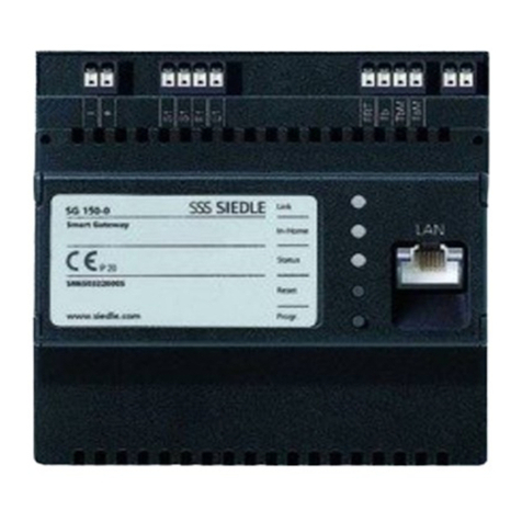
• SG150-…
• SNG850-…
• diese Produktinformation
Lieferumfang SET CLVSG 850-1
• FCLV13001B-…
• GUCL06-…
• ANG600-…
• SG150-…
• SNG850-…
• diese Produktinformation
Montage
Montageanleitungen nden sie in
den Produktinformationen der ein-
zelnen Geräte.
1 Schaltplan Vario-Set Smart
Gateway
2 Schaltplan Classic-Set Smart
Gateway
Reichweite
SNG850-… zur Türstation
max.100m,
SNG850-… zum entferntesten
Innengerät max. 100m, bei 0,8mm
Aderdurchmesser.
Klemmenbelegung BCM653-…
TaK, TbK In-Home-Bus
Kamerazweig
Ta, Tb In-Home-Bus
Vc, GND Kameraansteuerung
b, c Versorgungsspannung
12VAC

5
Technische Daten SNG850-…
Betriebsspannung:
230VAC, +/-10%, 50/60Hz
Betriebsstrom: 200mA
Ausgangsspannung: 27,5VDC,
12VAC
Ausgangsstrom: 0,5ADC, 1AAC
Absicherung: Primär Si
1T250mAL, sekundär kurzschluss-
fest
Kontaktart: 2 Schließer 24V, 2A
Schutzart: IP30
Umgebungstemperatur:
0°Cbis+40°C
Teilungseinheit (TE): 9
Abmessungen (mm) BxHxT:
162x89x60
Anzeige LED1 „Betrieb“
LED blinkt gleichmäßig
(Systemhochlauf) 0,3s 0,3s 0,3s 0,3s 0,3s usw.
LED blinkt kurz auf, lange aus
(Betriebsanzeige, Anlage in Funktion) 1s 20ms 1s 20ms usw.
LED blinkt kurz an, lange aus
(Programmiermodus aktiv) 0,3s 2s 0,3s usw.
LED immer an
(Plug+Play Programmierung ist aktiv)
Anzeige LED2 „Störung“
LED blinkt ungleichmäßig
(Mehr als 10 Teilnehmer) 2s 0,3s 0,3s 0,3s usw.
LED blinkt ungleichmäßig
Ungeeignetes Gerät im Plug+Play
Modus angeschlossen
0,3s 0,3s 0,2s 2s usw.
LED blinkt gleichmäßig
Keine Türstation im Plug+Play Modus
angeschlossen
2s 2s usw.
LED-Anzeigen SNG850-…

6
Link
In-Home
Status
Reset
Prog.
4 Sek.
1Programmiermodus am
SNG850-… aktivieren. Prog.- Mode
Taste kurz drücken, die LED1 blinkt
im 2Sekunden Rhythmus.
5Programmiervorgang beenden,
dazu am Set-Netzgerät die Prog.-
Mode Taste drücken. Die Ruftaste
ist jetzt dem SmartGateway
zugewiesen.
3 Prog.-Taste für 4Sekunden
drücken. Danach blinkt die LED
In-Home im Sekunden-Rhythmus.
Das Smart Gateway ist jetzt im
Programmiermodus.
Programmierung
4 Sek.
4 An der Türstation die gewünschte
Ruftaste für 4Sekunden gedrückt
halten, bis am Türlautsprecher ein
langgezogener Ton zu hören ist. Die
Ruftaste ist jetzt dem Bus-Innengerät
zugeordnet.
2a An der Türstation die Licht-/
Programmiertaste 4Sekunden
gedrückt halten. Danach ist ein
langgezogener Quittungston zu
hören, der alle 5Sekunden kurz
wiederholt wird, solange der
Programmiermodus aktiv ist.
2b An der Türstation die Program-
miertaste hinter der Frontplatte
4Sekunden gedrückt halten. Danach
ist ein langgezogener Quittungston
zu hören, der alle 5Sekunden
kurz wiederholt wird, solange der
Programmiermodus aktiv ist.

7
Inbetriebnahme Siedle App
Voraussetzungen:
• Anlage komplett aufgebaut
• Programmierung abgeschlossen
• Laptop und Smart Gateway
benden sich im gleichen Netzwerk
• IP-Adresse des Smart Gateway
bekannt
Verwendung von einer App
1 Webbrowser öffnen und
IP-Adresse des Smart Gateway ein-
geben.
2 Anmeldeseite öffnet sich,
Benutzername„admin“ und
Passwort„admin“ eingeben.
3 In den Bereich Netzwerk-
Teilnehmer, Unterpunkt
IP-Teilnehmer einen neuen
IP-Teilnehmer anlegen.
4 Namen frei vergeben z.B.
Benutzer1, den Bus-Adressverweis
der vordeniert ist auswählen und
mit weiter bestätigen.
5 QR-Code mit der Siedle App
scannen oder ausdrucken.
6 Die Inbetriebnahme ist abge-
schlossen, Browser schließen.
Verwendung von bis zu 6 Apps in
einer IP-Gruppe
1 Webbrowser öffnen und
IP-Adresse des Smart Gateway ein-
geben.
2 Anmeldeseite öffnet sich,
Benutzername„admin“ und
Passwort„admin“ eingeben.
3 In den Bereich Netzwerk-
Teilnehmer, Unterpunkt
IP-Teilnehmer einen neuen
IP-Teilnehmer anlegen.
4 Namen frei vergeben z.B.
Benutzer1, den Bus-Adressverweis
nicht auswählen und mit weiter
bestätigen.
5 QR-Code mit der Siedle App
scannen oder ausdrucken.
6 Punkt 3 bis 5 solange wiederholen
bis alle Appbenutzer angelegt sind.
7 In den Bereich Netzwerk-
Teilnehmer, Unterpunkt IP-Gruppen
eine neue IP-Gruppe anlegen.
8 Namen frei vergeben z.B.
Gruppe1, den Bus-Adressverweis*
der vordeniert ist auswählen, die
zuvor angelegten IP-Teilnehmer hin-
zufügen und speichern.
9 Die Inbetriebnahme ist abge-
schlossen, Browser schließen.
* Sollte der Bus-Adressverweis
nicht verfügbar sein, ist er bereits
einem anderen IP-Teilnehmer oder
IP-Gruppe zugewiesen und muss
dort gelöscht werden.

8
English
Terminal assignment
BTLM650-…
Ta, Tb In-Home bus
b, c Power supply 12VAC
Tö Relay contact door
release
Terminal assignment SG150-…
TaM, TbM In-Home bus monitor
branch
+, - Supply voltage
20–50VDC
ETb, ERT Storey call button
S1, S1 Potential-free contact
max.30VAC/DC, 2A
E1, E1 galvanically isolated
4–30VDC, 10mA
PE, PE Equipotential bonding
LAN
Terminal assignment ANG600-…
L1, N Power connection
+, - Output voltage
48VDC, 800mA
Terminal assignment SNG850-…
L1, N Power connection
Ta, Tb In-Home bus
b, c Power supply 12VAC
Tö, Tö Relay contact door
release
Li, Li Relay contact light
Commissioning
Easy commissioning by means of
manual programming.
Upgrade capability
The set can be extended with further
components. The overall extension
of the set must not exceed 10users,
whereby one door station supports
two users.
Application
The SmartGateway Vario/Classic
sets in bus technology contain all the
components you need to accept a
door call with video on your smart-
phone and open the door.
Performance features SNG850-…
• 10 bus addresses for supplying the
bus users
• Integrated door release and light
contact
• Programming: manual or via
BPS650-… (Windows PC) with
ZBVG650-… and PRI602-…USB
Electrical voltage
• Mounting, installation and ser-
vicing work on electrical devices may
only be performed by a suitably
qualied electrician. Failure to
observe this regulation could result
in the risk of serious damage to
health or fatal injury due to electric
shocks.
• Operation at an altitude of up to
2000m above sea level.
• Observe EN 62368-1! In a building
installation, an all-pole mains switch
with a contact opening of at least
3mm must be provided. The device
must not be exposed to water drops
or sprayed water! Sufcient ventila-
tion must be ensured. Pay particular
attention to ensure that ventilation
slots are not covered.
• When using stranded cores as
cable material, these must be tted
with wire end ferrules without fail.
Electrostatic charging
As a result of electrostatic charging,
direct contact with the circuit board
can result in destruction of the
device. Direct contact with the circuit
board must therefore be avoided.
Scope of supply SET VVSG 850-1
• BCM653-…W
• BTLM650-…W
• BTM650-…W
• KR611-3/1-…W
• MR611-3/1-…
• GU611-3/1-…
• ANG600-…
• SG150-…
• SNG850-…
• This product information
Scope of supply SET CLVSG 850-1
• FCLV13001B-…
• GUCL06-…
• ANG600-…
• SG150-…
• SNG850-…
• This product information
Mounting
Mounting instructions can be found
in the production information for
the individual devices.
1 Smart Gateway Vario set circuit
diagram
2 Smart Gateway Classic set circuit
diagram
Range
SNG850-… to door station
max.100m,
SNG850-… to the most remote
indoor device max. 100m, with
0.8mm core diameter.
Terminal assignment BCM653-…
TaK, TbK In-Home bus camera
branch
Ta, Tb In-Home bus
Vc, GND Camera actuation
b, c Power supply 12VAC
9
Specications SNG850-…
Operating voltage:
230VAC, +/-10%, 50/60Hz
Operating current: 200mA
Output voltage: 27.5VDC, 12VAC
Output current: 0.5ADC, 1AAC
Fusing: Primary fuse 1T250mAL,
secondary short circuit proof
Contact type:
2 n.o. contacts 24V, 2A
Protection system: IP30
Ambient temperature:
0°Cto+40°C
Horizontal pitch (HP): 9
Dimensions (mm) WxHxD:
162x89x60
Display LED1 “Operation“
LED ashes evenly
(System ramp-up) 0,3s 0,3s 0,3s 0,3s 0,3s etc.
LED ashes short on, long off
(Operation display, system is functional) 1s 20ms 1s 20ms etc.
LED ashes short on, long off
(Programming mode active) 0,3s 2s 0,3s etc.
LED remains alight
(Plug+Play programming is active)
Display LED2 “Fault“
LED ashes unevenly
(More than 10 users) 2s 0,3s 0,3s 0,3s etc.
LED ashes unevenly
Unsuitable device connected in
Plug+Play mode
0,3s 0,3s 0,2s 2s etc.
LED ashes evenly
No door station connected in
Plug+Play mode
2s 2s etc.
LED displays SNG850-…

10
Link
In-Home
Status
Reset
Prog.
4 Sek.
1 Activate the programming mode
on the SNG850-… Briey press the
programming mode button, LED1
ashes every 2seconds.
5 End the programming process by
pressing the programming mode
button on the set line rectier. The
call button is now assigned to the
SmartGateway.
3 Press the programming button for
4seconds. The In-Home LED then
ashes in a one-second rhythm. The
Smart Gateway is now in the pro-
gramming mode.
Programming
4 Sek.
4On the door station, press and
hold the desired call button for
4seconds until a sustained tone can
be heard from the door loudspeaker.
The call button is now assigned to
the bus indoor device.
2a At the door station, hold down
the light/programming button for
4seconds. A protracted acknowl-
edgement tone is then audible
which is repeated every 5seconds
as long as the programming mode
remains active.
2b On the door station, press and
hold the programming button
behind the front panel for 4sec-
onds. A sustained acknowledge-
ment tone will sound, which briey
repeats every 5seconds while pro-
gramming mode is active.

11
Commissioning Siedle App
Conditions:
• System fully set up
• Programming complete
• Laptop and Smart Gateway are in
the same network
• IP address of the Smart Gateway
is known
Using one app
1 Open your web browser and enter
the Smart Gateway’s IP address.
2 The login page appears. Enter the
username“admin” and the pass-
word“admin”.
3 Create a new IP user in the
Network users area, under IP users.
4 Assign a name freely, e.g. User1,
select the bus address reference
which is pre-dened and click Next
to conrm.
5 Scan the QR code with the Siedle
app or print it out.
6 Commissioning is complete. Close
the browser.
Using up to 6 apps in an IP group
1 Open your web browser and enter
the Smart Gateway’s IP address.
2 The login page appears. Enter the
username“admin” and the pass-
word“admin”.
3 Create a new IP user in the
Network users area, under IP users.
4 Assign a name freely, e.g. User1,
do not select the bus address refer-
ence and click Next to conrm.
5 Scan the QR code with the Siedle
app or print it out.
6 Repeat points 3 to 5 until all app
users have been created.
7 Create a new IP group in the
Network users area, under IP groups.
8 Assign a name freely, e.g. Group1,
select the bus address reference*
which is pre-dened, add the IP
users created previously and save.
9 Commissioning is complete. Close
the browser.
*If the bus address reference is not
available, it is already assigned to
another IP user or IP group and must
be deleted there.

12
Français
Implantation des bornes
BTLM650-…
Ta, Tb Bus In-Home
b, c Tension d’alimentation
12VAC
Tö Contact de relais gâche
Implantation des bornes
SG150-…
TaM, TbM Bus In-Home branche
moniteur
+, - Tension d’alimentation
20–50VDC
ETb, ERT Touche d’appel d’étage
S1, S1 contact sans potentiel
max.30VAC/DC, 2A
E1, E1 isolée galvaniquement
4–30VDC, 10mA
PE, PE Équilibre de potentiel
LAN
Implantation des bornes
ANG600-…
L1, N Raccordement au
secteur
+, - Tension de sortie
48VDC, 800mA
Implantation des bornes
SNG850-…
L1, N Raccordement au secteur
Ta, Tb Bus In-Home
b, c Tension d’alimentation
12VAC
Tö, Tö Contact de relais gâche
Li, Li Contact de relais lumière
Application
Le kit Vario/Classic de la
SmartGateway en technique bus
contient tous les composants néces-
saires pour recevoir l‘appel de porte
avec vidéo sur le smartphone et pour
ouvrir la porte.
Caractéristiques fonctionnelles
SNG850-…
• 10 adresses bus pour l’alimenta-
tion des postes bus
• Contact gâche et lumière intégrés
• Programmation: manuelle ou
via BPS650-… (PC Windows) avec
ZBVG650-… et PRI602-… USB
Tension électrique
• L’installation, le montage et l’en-
tretien d’appareils électriques ne
doivent être réalisés que par un spé-
cialiste en électricité. Le fait de ne
pas respecter cette consigne expose
à un risque de blessures graves ou à
un danger de mort par décharges
électriques.
• Exploitation à une altitude allant
jusqu’à 2000m au-dessus du
niveau de la mer.
• Respecter la norme EN 62368-1!
Un interrupteur général bipolaire,
avec une distance de contact ouvert
de 3mm au minimum, doit être pré-
sent dans l’installation du bâtiment.
L’appareil ne doit pas être exposé
aux gouttes d’eau ou aux projections
d’eau! Prévoir une ventilation suf-
sante et veiller en particulier à ne pas
masquer les fentes d’aération.
• Si l’on utilise des torons à titre de
câbles, ceux-ci doivent impérative-
ment être munis d’embouts.
Charge électrostatique
La charge électrostatique peut
détruire l’appareil en cas de contact
direct avec la carte de circuits
imprimés. Evitez par conséquent
tout contact direct avec la carte de
circuits imprimés.
Etendue de la fourniture
SET VVSG 850-1
• BCM653-…W
• BTLM650-…W
• BTM650-…W
• KR611-3/1-…W
• MR611-3/1-…
• GU611-3/1-…
• ANG600-…
• SG150-…
• SNG850-…
• La présente information produit
Etendue de la fourniture
SET CLVSG 850-1
• FCLV13001B-…
• GUCL06-…
• ANG600-…
• SG150-…
• SNG850-…
• La présente information produit
Montage
Les notices d‘installation se trouvent
dans les informations produits des
différents appareils.
1 Schéma de câblage du kit Smart
Gateway Vario
2 Schéma de câblage du kit Smart
Gateway Classic
Portée
SNG850-… vers la platine de rue
max.100m,
SNG850-… vers l’appareil intérieur
le plus éloigné max. 100m, pour un
diamètre de l de 0,8mm.
Implantation des bornes
BCM653-…
TaK, TbK Bus In-Home branche
caméra
Ta, Tb Bus In-Home
Vc, GND Commande de la caméra
b, c Tension d’alimentation
12VAC

13
Mise en service
Mise en service facile par program-
mation manuelle.
Extensibilité
Le kit peut être complété par
d‘autres composants. L‘installation
complète du kit ne doit pas dépasser
10postes tout en sachant qu‘une
platine de rue occupe deux postes.
Afchage LED1 “Fonctionnement“
La LED clignote régulièrement
(Montée en vitesse du système) 0,3s 0,3s 0,3s 0,3s 0,3s etc.
La LED s’allume brièvement, reste long-
temps éteinte (Afchage du fonction-
nement, installation en fonction)
1s 20ms 1s 20ms etc.
La LED s’allume brièvement, reste long-
temps éteinte (Mode programmation
actif)
0,3s 2s 0,3s etc.
LED éclairée en permanence (La pro-
grammation Plug+Play est active)
Afchage LED2 “Anomalie“
La LED clignote irrégulièrement
(Plus de 10 abonnés) 2s 0,3s 0,3s 0,3s etc.
La LED clignote irrégulièrement
Appareil inapproprié raccordé en
mode Plug+Play
0,3s 0,3s 0,2s 2s etc.
La LED clignote régulièrement
Pas de platine de rue raccordée en
mode Plug+Play
2s 2s etc.
Afchages à LED SNG850-…
Caractéristiques techniques
SNG850-…
Tension d’entrée :
230VAC, +/-10%, 50/60Hz
Courant de service : 200mA
Tension de sortie : 27,5VDC,
12VAC
Courant de sortie : 0,5ADC,
1AAC
Protection : Primaire Si
1T250mAL, secondaire résistant
aux courts-circuits
Type de contact :
2 contacts de travail 24V, 2A
Indice de protection : IP30
Température ambiante :
0°Cà+40°C
Unité de Division (UD) : 9
Dimensions (mm) lxHxP :
162x89x60

14
Link
In-Home
Status
Reset
Prog.
4 Sek.
1 Activer le mode programmation
sur le SNG850-… Appuyer briève-
ment sur la touche mode prog., la
LED1 clignote toutes les 2secondes.
5 Pour mettre n au processus de
programmation, appuyer sur la
touche mode prog. du bloc d'ali-
mentation du kit. La touche d'appel
est maintenant affectée à la Smart
Gateway.
3 Appuyer sur la touche prog. pen-
dant 4secondes. La LED In-Home
clignote ensuite toutes les secondes.
La Smart Gateway est à présent en
mode de programmation.
Programmation
4 Sek.
4 Sur la platine de rue, appuyer sur
la touche d’appel souhaitée pendant
4secondes, jusqu’à ce que l’on
entende une tonalité longue sur le
haut-parleur de porte. La touche
d’appel est maintenant affectée à
l’appareil intérieur bus.
2a Sur la platine de rue, maintenir
la touche lumière/programmation
appuyée pendant 4secondes. On
perçoit ensuite une tonalité d’acquit-
tement longue qui revient toutes les
5secondes brièvement, tant que le
mode programmation est actif.
2b Appuyer sur la touche de pro-
grammation se trouvant derrière
la façade de la platine de rue et
la maintenir enfoncée pendant
4secondes. Une longue tonalité
d‘acquittement retentit ensuite et
se répète brièvement toutes les
5secondes, tant que le mode pro-
grammation est actif.

15
Mise en service Siedle App
Conditions préalables:
• Installation entièrement assemblée
• Programmation terminée
• L‘ordinateur portable et la Smart
Gateway se trouvent dans le même
réseau
• Adresse IP de la Smart Gateway
connue
Utilisation d‘une application
1 Ouvrir le navigateur Web et saisir
l‘adresse IP de la Smart Gateway.
2 La page de connexion s'ouvre,
saisir l'identiant“admin” et le
mot de passe“admin”.
3 Créer un nouveau poste IP dans
le sous-menu Postes IP de la zone
Postes du réseau.
4 Attribuer un nom quelconque,
par ex. Utilisateur1, sélectionner la
référence d‘adresse bus prédénie et
conrmer avec Continuer.
5 Scanner ou imprimer le code QR à
l‘aide de l‘application Siedle.
6 La mise en service est terminée,
fermer le navigateur.
Utilisation de jusqu‘à 6 applica-
tions dans un groupe IP
1 Ouvrir le navigateur Web et saisir
l‘adresse IP de la Smart Gateway.
2 La page de connexion s'ouvre,
saisir l'identiant“admin” et le
mot de passe“admin”.
3 Créer un nouveau poste IP dans
le sous-menu Postes IP de la zone
Postes du réseau.
4 Attribuer un nom quelconque,
par ex. Utilisateur1, ne pas sélec-
tionner la référence d'adresse bus et
conrmer avec Continuer.
5 Scanner ou imprimer le code QR à
l‘aide de l‘application Siedle.
6 Répéter les points 3 à 5 jusqu‘à ce
que tous les utilisateurs de l‘applica-
tion soient créés.
7 Créer un nouveau groupe IP dans
le sous-menu Groupes IP de la zone
Postes du réseau.
8 Attribuer un nom quelconque,
par ex. Groupe1, sélectionner la
référence d‘adresse bus* prédénie,
ajouter et enregistrer les postes IP
précédemment créés.
9 La mise en service est terminée,
fermer le navigateur.
* Si la référence de l'adresse bus
n'est pas disponible, c'est qu'elle
est déjà affectée à un autre poste
IP ou groupe IP et qu'elle doit être
supprimée.

16
Italiano
Assegnazione dei morsetti
BTLM650-…
Ta, Tb In-Home-Bus
b, c Tensione di alimenta-
zione 12VAC
Tö Contatto a relè apriporta
Assegnazione dei morsetti
SG150-…
TaM, TbM In-Home-Bus
derivazione del monitor
+, - Tensione di
alimentazione
20–50VDC
ETb, ERT Tasto di chiamata dal
piano
S1, S1 contatto a potenziale
zero max.30VAC/
DC, 2A
E1, E1 galvanicamente
separato 4–30VDC,
10mA
PE, PE Compensazione del
potenziale LAN
Assegnazione dei morsetti
ANG600-…
L1, N Allacciamento alla rete
+, - Tensione di uscita
48VDC, 800mA
Assegnazione dei morsetti
SNG850-…
L1, N Allacciamento alla rete
Ta, Tb In-Home-Bus
b, c Tensione di alimenta-
zione 12VAC
Tö, Tö Contatto a relè apriporta
Li, Li Contatto a relè luce
Messa in funzione
Facile messa in funzione grazie alla
programmazione manuale.
Impiego
Il set Vario/Classic SmartGateway
nel sistema bus contiene tutti i
componenti necessari per ricevere la
chiamata dal posto esterno con rela-
tiva immagine e aprire la porta, tutto
sullo smartphone.
Prestazioni SNG850-…
• 10 indirizzi bus per l’alimentazione
degli utenti bus
• Contatto apriporta e contatto luce
integrati
• Programmazione: manuale o tra-
mite BPS650-… (PC Windows) con
ZBVG650-… e PRI602-… USB
Tensione elettrica
• Gli interventi di installazione, mon-
taggio e assistenza degli apparecchi
elettrici devono essere eseguiti esclu-
sivamente da elettricisti specializzati.
In caso di mancato rispetto di questa
avvertenza sussiste il pericolo di gravi
danni per la salute o di morte per
folgorazione elettrica.
• Funzionamento ad un’altezza no
a 2000m sul livello del mare.
• Rispettare la norma EN 62368-1!
Nell’impianto dell’edicio deve
essere previsto un interruttore di rete
onnipolare con un’apertura di con-
tatto di almeno 3mm. L’apparecchio
non deve essere esposto a stillicidio
o spruzzi d’acqua! Occorre garantire
una sufciente ventilazione, accer-
tandosi in particolare che la feritoia
di aerazione non venga coperta.
• Se come cavi si utilizzano cavetti,
occorre dotarli assolutamente di
guaine per estremità di li.
Carica elettrostatica
In caso di contatto diretto con il cir-
cuito stampato, l’apparecchio può
subire danni irreparabili a causa della
carica elettrostatica. Evitare quindi di
toccare direttamente il circuito stam-
pato.
Kit di fornitura SET VVSG 850-1
• BCM653-…W
• BTLM650-…W
• BTM650-…W
• KR611-3/1-…W
• MR611-3/1-…
• GU611-3/1-…
• ANG600-…
• SG150-…
• SNG850-…
• Il presente opuscolo informativo
sul prodotto
Kit di fornitura SET CLVSG 850-1
• FCLV13001B-…
• GUCL06-…
• ANG600-…
• SG150-…
• SNG850-…
• Il presente opuscolo informativo
sul prodotto
Montaggio
Le istruzioni di montaggio sono
incluse nell’opuscolo informativo sul
prodotto allegato a ciascun appa-
recchio.
1 Schema elettrico Set Vario
SmartGateway
2 Schema elettrico Set Classic
SmartGateway
Raggio d’azione
SNG850-… per il posto esterno
max.100m,
Distanza fra l’SNG850-… e l’ap-
parecchio interno più lontano max.
100m, con li dal diametro di
0,8mm.
Assegnazione dei morsetti
BCM653-…
TaK, TbK In-Home-Bus derivazione
della telecamera
Ta, Tb In-Home-Bus
Vc, GND Comando telecamera
b, c Tensione di alimenta-
zione 12VAC

17
Estendibilità
Il set può essere esteso con ulteriori
componenti. L‘estensione totale del
set non deve superare 10utenti,
tenendo conto che un posto esterno
occupa due utenti.
Dati tecnici SNG850-…
Tensione d’esercizio: 230VAC,
+/-10%, 50/60Hz
Corrente d’esercizio: 200mA
Tensione di uscita: 27,5VDC,
12VAC
Corrente iniziale: 0,5ADC, 1AAC
Protezione: Lato primario Si 1
T250mAL, lato secondario protetto
da cortocircuito
Indicatore LED1 “funzionamento“
Il LED lampeggia uniformemente
(lancio del sistema) 0,3s 0,3s 0,3s 0,3s 0,3s ecc.
Il LED lampeggia brevemente acceso,
a lungo spento
(indicatore di funzionamento,
impianto in funzione)
1s 20ms 1s 20ms ecc.
Il LED lampeggia brevemente acceso,
a lungo spento
(modalità programmazione attiva)
0,3s 2s 0,3s ecc.
LED sempre acceso
(programmazione Plug+Play attiva)
Indicatore LED2 “anomalia“
Il LED lampeggia non uniformemente
(più di 10 utenti) 2s 0,3s 0,3s 0,3s ecc.
Il LED lampeggia uniformemente
Apparecchio inadeguato collegato in
modalità Plug+Play
0,3s 0,3s 0,2s 2s ecc.
Il LED lampeggia uniformemente
Nessun posto esterno collegato in
modalità Plug+Play
2s 2s ecc.
Indicatori LED SNG850-…
Tipo di contatto: 2contatti normal-
mente aperti, 24V, 2A
Tipo di protezione: IP30
Temperatura ambiente:
da0°Ca+40°C
Unità di modulare: 9
Dimensioni (mm) Larg.xAlt.xProf.:
162x89x60

18
Link
In-Home
Status
Reset
Prog.
4 Sek.
1 Attivare la modalità program-
mazione sull’SNG850-… Premere
brevemente il tasto Prog.- Mode;
il LED1 lampeggia ad intervalli di
2secondi.
5Terminare la procedure di pro-
grammazione premendo il tasto
Prog.- Mode sull’alimentatore del
set. Il tasto di chiamata è ora asse-
gnato allo SmartGateway.
3 Premere il tasto Prog.-Mode per
4secondi. A questo punto, il LED
In-Home lampeggia ad intervalli di
un secondo. Lo SmartGateway si
trova ora in modalità programma-
zione.
Programmazione
4 Sek.
4Sul posto esterno tenere premuto
il tasto di chiamata desiderato per
4secondi, nché non si sente un
suono prolungato sul porter. Il tasto
di chiamata è ora assegnato all’ap-
parecchio interno bus.
2a Sul posto esterno tenere premuto
il tasto di programmazione/luce per
4secondi. Si sente quindi un suono
di conferma prolungato, che viene
ripetuto brevemente ogni 5secondi,
nché la modalità programmazione
rimane attiva.
2b Sul posto esterno tenere pre-
muto il tasto di programmazione
dietro il frontalino per 4secondi.
Successivamente si sente un suono
di conferma prolungato, che si ripete
brevemente ogni 5secondi nché è
attiva la modalità programmazione.

19
Messa in funzione Siedle App
Premesse:
• Impianto completamente montato
• Programmazione terminata
• Il laptop e lo SmartGateway si
trovano nella stessa rete
• Indirizzo IP dello SmartGateway
noto
Utilizzo di una app
1 Aprire il web browser e inserire
l’indirizzo IP dello SmartGateway.
2 Si apre la pagina di registra-
zione dove inserire il nome
utente“admin” e la pas-
sword“admin”.
3 Nella sezione Utenti di rete, sot-
tovoce Utenti IP, inserire un nuovo
utente IP.
4 Assegnare un nome a piacere,
ad es. Utente 1, selezionare il riferi-
mento di indirizzo bus predenito e
confermare con Avanti.
5 Scansionare il codice QR con la
SiedleApp oppure stamparlo.
6 La messa in funzione è così ter-
minata, quindi si può chiudere il
browser.
Utilizzo di un numero massimo di
6 app in un gruppo IP
1 Aprire il web browser e inserire
l’indirizzo IP dello SmartGateway.
2 Si apre la pagina di registra-
zione dove inserire il nome
utente“admin” e la pas-
sword“admin”.
3 Nella sezione Utenti di rete, sot-
tovoce Utenti IP, inserire un nuovo
utente IP.
4 Assegnare un nome a piacere, ad
es. Utente 1, non selezionare il riferi-
mento di indirizzo bus e confermare
con Avanti.
5 Scansionare il codice QR con la
SiedleApp oppure stamparlo.
6 Ripetere i punti dal 3 al 5 il
numero di volte necessario per
creare tutti gli utenti della app.
7 Nella sezione Utenti di rete, sot-
tovoce Gruppi IP, creare un nuovo
utente IP.
8 Assegnare un nome a piacere, ad
es. Gruppo 1, selezionare il riferi-
mento di indirizzo bus* predenito,
aggiungere l’utente IP precedente-
mente creato e salvare.
9 La messa in funzione è così ter-
minata, quindi si può chiudere il
browser.
*Qualora non fosse disponibile il
riferimento di indirizzo bus, signica
che è assegnato ad un altro utente IP
o gruppo IP e che tale assegnazione
deve essere cancellata.

20
Nederlands
Klemmenindeling BTLM650-…
Ta, Tb In-Home-Bus
b, c Verzorgingsspanning
12VAC
Tö Relaiscontact
deuropener
Klemmenindeling SG150-…
TaM, TbM In-Home-Bus
monitortak
+, - Verzorgingsspanning
20–50VDC
ETb, ERT Etage-oproeptoets
S1, S1 potentiaalvrij contact
max.30VAC/DC, 2A
E1, E1 galvanisch gescheiden
4–30VDC, 10mA
PE, PE Potentiaalvereffening
LAN
Klemmenindeling ANG600-…
L1, N Netaansluiting
+, - Uitgangsspanning
48VDC, 800mA
Klemmenindeling SNG850-…
L1, N Netaansluiting
Ta, Tb In-Home-Bus
b, c Verzorgingsspanning
12VAC
Tö, Tö Relaiscontact deuropener
Li, Li Relaiscontact licht
Ingebruikname
Eenvoudige ingebruikname door
handmatige programmering.
Uitbreidbaarheid
De set kan door verdere compo-
nenten worden uitgebreid. De
gehele uitbouw van de set mag het
aantal van 10deelnemers niet over-
schrden, waarb een deurstation
twee deelnemers inneemt.
Toepassing
De Vario-/Classic-Sets Smart
Gateway in Bus-Techniek bevat
alle benodigde componenten om
de deuroproep met video op de
Smartphone aan te nemen en de
deur te openen.
Prestatiekenmerken SNG850-…
• 10 bus adressen voor de verzor-
ging van de bus-toestellen
• geïntegreerd deuropener- en licht-
contact
• programmering: handmatig of
via BPS650-… (Windows-PC) met
ZBVG650-… en PRI602-… USB
Elektrische spanning
• Inbouw, montage en onderhouds-
werkzaamheden aan elektrische
apparaten mogen uitsluitend door
een elektro-vakman worden uitge-
voerd. B het niet opletten bestaat
het gevaar op zware schade aan de
gezondheid of levensgevaar door
elektrische schokken.
• Gebruik op een hoogteniveau tot
maximaal 2000m boven de zee-
spiegel.
• EN 62368-1 naleven! In de instal-
latie in het gebouw dient een
alpolige netschakelaar met een
contactopening van minimaal 3mm
beschikbaar te zn. Het apparaat
mag niet aan drup- of spuitwater
worden blootgesteld! Er dient te
worden gezorgd voor toereikende
beluchting, in het bzonder dient te
worden gezorgd dat de beluchtings-
sleuven niet worden afgedekt.
• B gebruik van kabelstrengen
als kabelmaterialen dienen deze
dwingend te worden voorzien van
adereindhulzen.
Elektrostatische lading
Door elektrostatische lading kan b
een direct contact met de printplaat
het apparaat worden vernietigd.
Vermdt u daarom het direct aan-
raken van de printplaat.
Leveringsomvang
SET VVSG 850-1
• BCM653-…W
• BTLM650-…W
• BTM650-…W
• KR611-3/1-…W
• MR611-3/1-…
• GU611-3/1-…
• ANG600-…
• SG150-…
• SNG850-…
• Deze productinformatie
Leveringsomvang
SET CLVSG 850-1
• FCLV13001B-…
• GUCL06-…
• ANG600-…
• SG150-…
• SNG850-…
• Deze productinformatie
Montage
Montage handleidingen vindt u in
de productinformatie van de indivi-
duele apparaten.
1 Schema Vario-Set Smart Gateway
2 Schema Classic-Set Smart Gateway
Reikwdte
SNG850-… naar het deurstation
max.100m,
SNG850-… naar het verste binnen-
apparaat max.100 m, b 0,8mm
aderdoorsnede.
Klemmenindeling BCM653-…
TaK, TbK In-Home-Bus cameratak
Ta, Tb In-Home-Bus
Vc, GND Camera-aansturing
b, c Verzorgingsspanning
12VAC
This manual suits for next models
1
Table of contents
Languages:
Other SSS Siedle Gateway manuals

SSS Siedle
SSS Siedle FPM 611-02 User manual

SSS Siedle
SSS Siedle Smart Gateway Professional Training manual

SSS Siedle
SSS Siedle AGW 671-0 User manual

SSS Siedle
SSS Siedle SG 150-0 User manual

SSS Siedle
SSS Siedle SET CVSG 850-1 Guide

SSS Siedle
SSS Siedle Smart Gateway Training manual

SSS Siedle
SSS Siedle SG 650-0 User manual

SSS Siedle
SSS Siedle SG 650-0 Installation and operation manual

SSS Siedle
SSS Siedle SG 650-0 User manual

SSS Siedle
SSS Siedle Smart Gateway Professional User manual