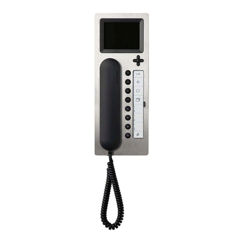
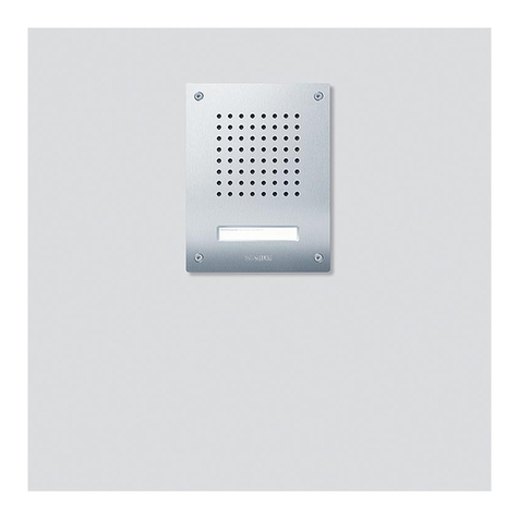
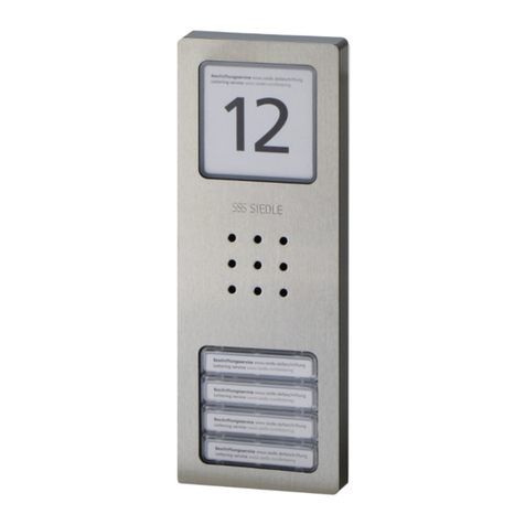
Industrial call station
AICI 3000-... surface mounting
8 Open the housing as illustrated
and remove the ribbon cable on the
terminal pcb.
9 Fasten the bottom part of the
housing to the wall using 4 screws.
Cable entry via screw glands are
optional from above or below. If
cable entry takes place from above,
the terminal pcb must be removed
and replaced at the bottom.
The system installation is connected
at the 10-pole terminal strip J1. It is
possible to additionally mount a
loudspeaker (4 Ω) provided by the
user at the 4-pole terminal strip J4
via amplifier ZVI 2010 or VZ 85859.
Alternatively to the integrated
microphone, any standard commer-
cially available microphone can be
connected at the M+ and M- termi-
nals of this terminal strip.
10 If an external microphone is
connected, the microphone jum-
pers must be repositioned on the
keypad pcb from "internal" to
"external". At the 6-pole terminal
strip J6, if necessary the external
signal appliances for call and alarm
tone (22-23, 32-33) are connected,
and via a floating contact also the
input E1-2.
11 Plug the ribbon cable to socket
JP1 / JP3 on the connecting pcb,
and close the housing.
12 The call tone volume is set using
the potentiometer P1.
13 Wire diagram
Caution
Cable entries which are not used
must not be broken out, or must
be protected by a blanking plug.
Industrial call station
UICI 3000-... flush mounting
14 Insert the cable through the rear
wall of the provided flush mount
housing and mount.
15 Open the housing as indicated
and take the flat ribbon cable off
the connecting pcb.
16 Use the 4 provided screws
M4 x 25 to fasten the housing base
4
in the mounted housing. The
method of cable entry is optional. If
the cable enters from above, the
connecting pcb in the housing must
be removed and positioned at the
bottom.
The system installation is connected
at the 10-pole terminal strip J1. It is
possible to additionally mount a
loudspeaker (4 Ω) provided by the
user at the 4-pole terminal strip J4
via amplifier ZVI 2010 or VZ 85859.
Alternatively to the integrated
microphone, any standard commer-
cially available microphone can be
connected at the M+ and M- termi-
nals of this terminal strip.
17 If an external microphone is
connected, the microphone jum-
pers must be repositioned on the
keypad pcb from "internal" to
"external". At the 6-pole terminal
strip J6, if necessary the external
signal appliances for call and alarm
tone (22-23, 32-33) are connected,
and via a floating contact also the
input E1-2.
18 Plug the ribbon cable to socket
JP1 / JP3 on the connecting pcb,
and close the housing.
19 The call tone volume is set using
the potentiometer P1.
20 Wire digram
For operating characteristics, requi-
red appliances and circuit diagrams,
see "Siedle Intercom Planning and
Installation".
Français
Montage
Application
Le Siedle Intercom SIC/ICI 3000-...
est un système de communication
bidirectionnel, simultané commandé
par la voix à structure numérique et
prévu pour le montage mural en
saillie. Mais l'appareil peut égale-
ment être encastré ou monté sur
table
avec les accessoires correspondants
disponibles. En outre, il peut être
combiné avec le module multifonc-
tions MFM 611-10 et/ou le moniteur
MOM/MOC 611/711-..., et ce indé-
pendamment de la variante de mon-
tage: encastrée, en saillie ou sur
table.
Le poste intercom industriel
AICI 3000-... pour montage en sail-
lie et le poste intercom industriel
UICI 3000-... pour montage encastré
sont conçus pour l´usage profession-
nel. Deux contacts secs sont prévus
pour la signalisation des tonalités
d´appel et de réponse, plus une ent-
rée programmable qui peut être
programmée au choix comme une
touche du module MFM 611-10.
Important
En cas de montage en saillie ou
encastré de l´Intercom Siedle
3000-..., il faut toujours l´accessoire
ZAV 3000-0 pour le branchement.
Pour les postes intercom industriels
AICI/UICI 3000-..., par contre,
l´accessoire ZAV 3000-0 n´est pas
nécessaire.
Montage en saillie SIC 3000-...
Une double prise est nécessaire pour
le branchement et la fixation du
distributeur ZAV 3000-0.
1Ouvrir le boîtier comme illustré par
le schéma.
2Visser la partie inférieure du boî-
tier sur le mur avec 4 vis.
Brancher l'installation système sur le
connecteur à 12 bornes J3/J4. Le
connecteur à 4 bornes J1 permet
d'alimenter ou de commander un
moniteur. La fiche à 2 bornes J2 sert
à brancher une touche d'appel de
l'étage. Le câble plat raccordé sur
JP1 doit également être raccordé sur
JP1dans l'Intercom Siedle SIC 3000-...


