4
17 Adresseinstellung mit den
Schiebeschaltern.
(Siehe Programmieranleitung)
Demontage
18 Zum Abnehmen des Gehäuses
mit einem Schlitz-Schraubendreher
die Verriegelung nach oben
drücken. Leiterplatte und Hörer
verbleiben am Gehäuse-Oberteil.
Beschriftung
19 Das Beschriftungsfeld kann mit
den Tastenfunktionen entsprechend
beschriftet werden. Die Sichtscheibe
kann seitlich angehoben werden.
Einstellung der Ruftonlautstärke
20 Unter der Schrifteinlage ist das
Potentiometer für die Einstellung der
Ruftonlautstärke zugänglich.
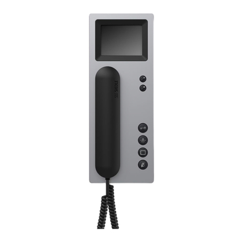
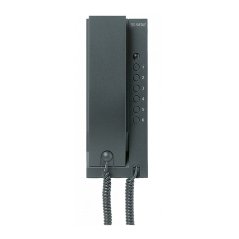
21 Tastenbelegung des Gerätes.
Zubehör für HT 840-...
•ZT 840-... für die Umrüstung von
Wandgerät zu Tischgerät.
Geräteadresse einstellen
Inbetriebnahme
Nach ordnungsgemäßer Montage
und Installation wird in stromlosen
Zustand an jedem Gerät eine
Adresse eingestellt (Bild 16, Einstel-
lung Geräteadresse).
Maximal 4 Geräte können mit der
gleichen Adresse versehen werden,
was bedeutet, dass diese Geräte
dann parallel geschaltet sind.
An zentraler Stelle wirddie Anlage
eingeschaltet und nach kurzer Zeit,
max. 3 Minuten ist die Anlage im
Auslieferzustand (Grundkonfigura-
tion 6) betriebsbereit.
Konfiguration festlegen
Im Auslieferzustand ist immer die
Grundkonfiguration 6 festgelegt.
Eine Konfiguration kann nicht
gelöscht sondernnur überschrieben
werden.
In einer Anlage können Geräte
(HT 840-...) mit unterschiedlichen
Konfigurationen ausgestattet sein.
Dabei orientiert sich der Leistungs-
umfang der Gesamtanlage immer
an der niedrigsten Konfigurations-
stufe.
Der Mischbetrieb ist jedoch nur
zwischen den Konfigurationen 1-3
bzw. 4-6 erlaubt.
Programmier-Schalter-Stellung
Bei manueller Programmierung am
Schiebeschalter den Schalter 10 (FP)
zur Programmierung auf “Ein”
stellen und danach für den
Betriebszustand wieder auf “Aus”
stellen.
Ist ein SCO 740-... in der Anlage
integriert, so muss der Schalter
immer auf “Aus” gestellt sein.
Grundkonfiguration
Die 6 festgelegten Grundkonfigu-
rationen können ohne weitere Hilfs-
mittel abgerufen werden.
Bei eingeschaltetem Schiebeschalter
10 (FP) die Licht- und Türöffnertaste
gleichzeitig drücken, gedrückt
halten und zusätzlich die Ziffer (1-6)
für die gewünschte Konfiguration
drücken.
Nach ca. 3 Sekunden leuchten die
beiden LED’s unter der Türöffner-
und Lichttaste kurz auf. Damit ist
die Konfiguration für dieses Gerät
bestätigt. Im Handapparat ertönt
zusätzlich ein Quittungston.
Der Schiebeschalter 10 (FP) muss
nach der Konfiguration wieder
ausgeschaltet werden.
System-Konfiguration
Mit Hilfe der Systemkonfiguration
können alle angeschlossenen
HT 840-... mit allen Kombinations-
möglichkeiten des Systems
individuell konfiguriert werden.
Grundvoraussetzung für die System
konfiguration ist immer ein System-
Controller SCO 740-...
Über ein PRI 602-... kann daran ein
PC angeschlossen werden, der die
Konfiguration erleichtertund über
den die Konfiguration aller Teil-
nehmer ausgelesen, gespeichert
und ausgedruckt werden kann.
NähereAngaben hierzu finden Sie
in der Programmieranleitung des
SCO 740-...
Erweiterte Konfiguration
Bei der Erweiterten Konfiguration
können individuelle Änderungen
vorgenommen werden. Diese
können ausschließlich durch eine
geschulte Elektro-Fachkraft
durchgeführt werden.
Nähere Information erhalten Sie
über die Siedle-Multi-Hotline
Telefon +49 7723 63-378
