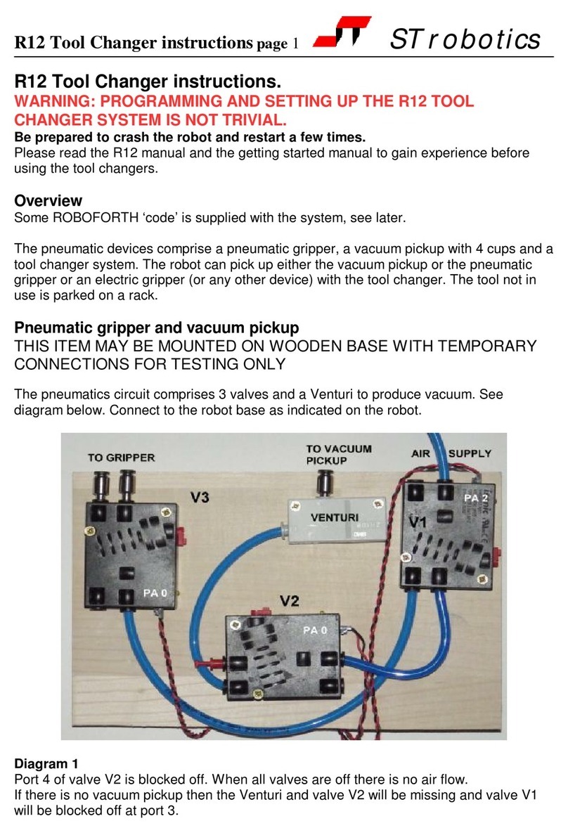
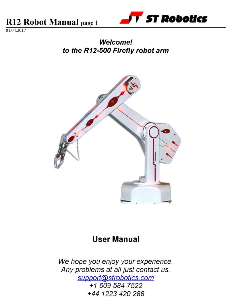
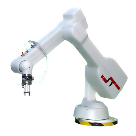
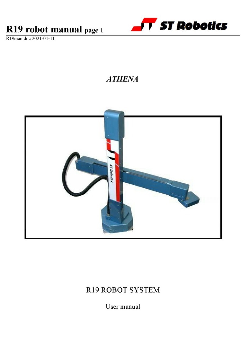
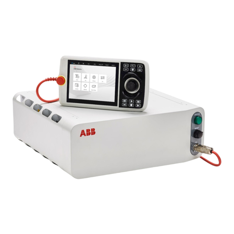
ST Robotics R17 User manual

R17 RobotManual page 2
SystemComponents:
AbasicR17 robot systemcomprisesthe following:-
1R17 Robot arm
Fitted withanyoptions:
Pneumaticor electricgripper
Vacuumpickup
PneumaticToolChanger
6th axismodule
1 Controller K11R
Fitted withanyoptions:
I/O expansion
Gripper drivemodule
1Teachbox
1Cable9-wayD-type eachend (M-M)-K11Rtoteachbox
1Motor cable-K11RMSconnector torobot 25-wayD-type
1Sensor and encoder cable-25-wayeachend (M-F)
1Cable, D-type 25-waymaleto9-wayfemale-K11RtoPCRS232
1Power cabletoK11R
1Packof CONNECTORS:
1output connector
1input connector
1Diskwithsoftware and manuals.
1optionalUSB/serialadaptor
1 optionalAndroidteachconsole.
1Gripper pneumatics kit
1Quickstop pneumatics kit
Manual Contents:
1Introduction
2Important Dosand Don'ts
3Setting up
4Computer
5Controller
6Preparing for Use
7Getting Started
8Accessories
9Controller Settings
10 Robot Parameters
11 Full Calibration fromscratch
12 Connections
13 Collisions
14 TechnicalSupport

R17 RobotManual page 3
1. INTRODUCTION
The R17, DEUCALIONisarobot armof the verticallyarticulated format. Thisisthe format
whichmost closelyresemblesthe human armand soitspartsarenamed afterthe human
arm. It ismoreversatilethan otherformatsbut the drawback isthat backlashand
complianceineachjoint areadded togetherjoint byjoint. R17 hasanominalreachof
750mm i.e. it is750 mm fromthe shoulderjoint tothe wrist, plusanother100 mm orsofor
the hand, depending on the "end effector"fitted. R17 and R17HPLaredriven bystepping
motorsmicrostepsof 0.18 degreesperstep resulting aftergearing inanominalresolution
of 0.1mm orbetterat the end effector. R17HS hasaxes4and 5driven bystepping
motors; axes1,2and 3aredriven byhigh powerservomotors.
If fitted the pneumaticgripperisoperated bycompressed airfrom3to7bar. Thismaybe
supplied byacompressorsupplied withthe set, orfromanotherairsupply.
The R17 robot systemcomprises3mainunits:-the robot, the controller, acomputeror
dumbterminal. The computerisused toprogramthe controller. Onceprogrammed the
controllerwill run the robot independentlywithout the need foracomputerbut it isagood
idea toleavealowcost terminalconnected whilethe robot isinuse.
OVERVIEW
The controllercontrolsall movement of the robot. Asthe controllermaybe bothreading
sensorsand signalsfromand controlling associated equipment it followsthat all decisions
about robot activityareusuallymade bythe controllerwhichiscapableof running without
anyhost computer. The function of the computeristo(a)programthe controller, (b)to
copy(back up)the contentsof controllerRAMtodisk and optionally(c)toperforma
supervisoryrolesending commandstothe controllerthrough the serialinterface.
Toprogramthe controllerwithacomputeryou need torun the utilityROBWIN7.EXE.
When ROBWINisexecuted it immediatelyopensacommunicationswindow. Once
communication isestablished all yourcommandsgo tothe controllernot tothe computer
you aretyping on. Programming the controllerinvolvesprogramming the robot and the
interaction withotherequipment. The robot and interfacing areprogrammed using
ROBOFORTHII © and FORTH. Therearetwomanuals, ROBOFORTHcovering robot
programming and the systemmanual, whichdescribesthe controllerand interfacing. The
softwaremanualsareon disk and written inHTMLsoyou can usedynamiclinks tosee
connected concepts. Thereisalsoaglossaryon disk, whichgivesabrief description of
everycommand. Somecommandsareused onlybyROBWINorarenot veryusefuland
theseareinthe glossarybut not inthe ROBOFORTHmanual.
All FORTHand ROBOFORTHcommandsareinUPPERCASE (press capslock). You
can add commandswritten inlowercasebut thesewouldbe different commandsfrom
thosespelled inuppercase.
©RoboForthiscopyright DavidNSands1983-present

R17 RobotManual page 4
2. IMPORTANTDOSAND DON'TS
(1)DON'T everdisconnectorconnect the robot whilethe controllerisswitched on. This
will result indamage tothe electronics and the connectorsthemselves. Warrantyclaims
will not be accepted fordamage resulting fromthis.
Onthe R17HSorR17HSWdo not leavethe motorcabledisconnected but the power
cableconnected orviceversa.
(2)DO be verycarefulnot to"crash" i.e. driveanyjoint against asolidobject sothat it
stalls. Depending on the speed damage mayresult. At lowerspeedsthe motorsgenerate
highertorquessocan do moredamage. DON'T drivethe waist against the stop.
(3)Forthe abovereason DON’TuseCALIBRATEunless you aresurethe robot will not
crashintosomething inthe workspace.
(4)DON'T useCALIBRATEunless you aresurethe robot isinthe validposition for
calibration including taking intoaccount anycomplexend effectorfitted.
(5)DON'T back-drivethe 6th axis; damage can result.
(6)DO haveyourhand poised overthe emergency stop button whenevertesting a
program. Rememberthat becauseof itsgeometryarevolutearmwill describe wide arcs
fromfarapart points, and maycollide withobjectswithinitsreach.
(7)DO takeappropriatemeasurestoassess the risks and protect personnelfrominjury
(see next section)
(8)DON’Tcontinuouslyrotatean electricgripper–it will breakthe internalwiring.
(9)DON’Tleavethe robot switched on but not moving forverylong periodsof time(say
morethan aweek)asmotorheat can damage the belts.
(10)DON’Ttrytosaveaproject if the controllerisswitched off.
(11)DO makeaback-up of the computerdisk supplied assoon aspossible.
(12)DO warmup the robot forbest repeatability. Afterswitching on fromcoldrun the
robot somesimpleall axesroutine for10-20 minutes.

R17 RobotManual page 5
SAFETYISYOUR RESPONSIBILITY
Risks
Becausestepping motorsraisemoretorque at lowspeedsasubstantiallowspeed force
can be brought tobearespeciallyon fingerswhichmaybecometrapped underor
between axes. Robot end effectorstypicallyhavesharpedgesorfingersmade of thin
metalwhichcan causeinjuryat the lowspeed high forcesorat the higherspeeds.
The biggest risk comesfromthe element of surprise. If the systemisactiveand receives
acommand fromasupervising schedulerorasignalfroman associated machine the
robot will appeartomoveunpredictably. Ahuman being caught inthe waycan receive
injury, especiallyif the end effectorhassharpedges.
However, becausethe robot issteppermotordriven, oncestalled the systemraisesan
errorand doesnot attempt furthermotion.
Safetymeasures
•Wherepossiblearobot systemshouldbe guarded. Anygateinthe guarding can
be fitted withaswitch, whichisconnected tothe controllerstop circuit.
•If physicalguardscannot be provided then light curtainsareeasilyconnected tothe
robot controllerorthe STSentrysensorsystem.
•Whereguarding isnot appropriateand bench-top robotsworkcloselywithhuman
workersinterlocks shouldbe provided. Forexampleif the userhasaccess tothe
workspacethen he/she shouldbe required topress aswitchorkeyboardkeyafter
clearing the area. The STSentrysystemcan be used sothat if ahuman entersthe
workspacethe robot will stop. It can be programmed todisplayamessage and wait
forakeyboardinput beforecontinuing.
•Agood ruleisthat the robot shouldnot be allowed tomoveoutside an area
designated bythe edge of the benchon whichit ismounted.
•Asan additionalprecaution the working area couldbe marked out withpainted
linesorblack/yellowstriped tape.
•Statisticallythe highest incidenceof contention between human and robot iswhen
bothareaccessing the sameobject. End effectorsoften havesharpedgeswhich
can causeinjury. Fitting acollision sensorcan minimizethishazard.
•At the end of thismanualyou will find aformwithwhichtodo yourownrisk
assessment of the robot inyourapplication. Therearetwoconceptstoconsider:
hazard, whichisthe robot orrobot fingersorthe product etc. and risk, whichisthe
probabilityof someone being harmed bythe hazard. The formenablesyou to
identifythe hazards, the risks and ways of minimizing the risks. Aftercompleting
the formand carrying out anysafetymeasuresthat the formhashelped you
identify, do the assessment all overagain.

R17 RobotManual page 6
3. SETTING UP
Set the robot up inthe desired location. Connect up all cables-theirpositionsshouldbe
self-evident. Cablestothe robot connect tothe rearof the controller.
Thereare5basiccables:
Motorpower –the metalized cablefromrearof controllertorobot base, 26wMSto25wD
Sensorcable –fromrearof controllertorobot base(25wDmaleto25wDfemale)
Grippercable (if supplied)-fromrearof controllertogrippervalve(9wDtoDIN)
Serial cable –fromfront of controllertocomputer(usually25wDmaleto9wDfem)
Teachpadcable –fromfront of controllertoteachpad (9wDto9wDmaletomale).
Thereisalsoa Stop Jack forconnecting an externalstop circuit. Even if thereisno
externalstop circuit the jackplug must be plugged inat the rearof the controller. The plug
hasashorting link, whichisremoved when connecting an externalcircuit.
The serial(RS232 null modem)cablefromacomputertothe controllershouldplug into
the 25-wayDconnectoron the front of the controller. The otherend (usually9wD)
connectstothe rearCOM1serialconnectorof the computer. If COM1isalreadyinuse
you can useanyCOMport orthe USB serialadapter(see laterforconfiguration). The
serialspeed is19200 Baud, 8bits, 1stop bit.
DOSutilitiesonlyworkwithCOM1. You can still usethe DOSutilitiesif you havealegacy
computerorarerunning aDOSsimulatorsuchasDOSBOX.
R17HS alsohas
Powercable
Note: the motorpowercablecontainspowerdrivestoaxes4and 5but digitalsignalsto
axes1,2,3

R17 RobotManual page 7
Pneumaticconnections
Connect the airline bypushing it intothe push-fit connectorson the airvalveand twofrom
the valvetothe rearof the robot. If thereisno compressorsupplied then connect the shop
airsupplytothe airvalve. The airsupplymust haveabowlfilterand apressureregulator.
Pneumaticgripper
If apneumaticgripperisfitted the robot will havetwoairlinesfitted through it, emerging on
the forearmon twopush-fit connectors. Twoexternallinesloop tothe gripper. The control
valveisusuallyexternal. The valveisoperated fromoutput port PA bit 0.
Electricgripper
If the electricgripperisfitted thisiswired through the robot and requiresno installation by
the customer. It isoperated byadrivemoduleinthe controller. It iscontrolled fromoutput
port PA bits0and 1. Onlyusethe commandsGRIPand UNGRIP. The softwareswitches
the motoron/off veryfast tocontrolthe speed of closing and opening (PWM). When
closed PA 0isset toa1and left on tocontinuouslyenergizethe motorand maintain
gripping force. AfterUNGRIPthe motorisleft non-energized.
Ared LEDshowswhen the gripperispowered (see diagrambelow).
Note: the electricgripperishardwired through the wrist mechanism. Makesureyou limit
rotation to360 degrees. If you go past the wrist rotatesensorand do anotherCALIBRATE
thismayresult inanother360 degrees. Eventuallythe wireswill twist and break. It should
be enough tosend UNTWISTbeforeeachCALIBRATE.
If indoubt removethe wrist cover(1screwand 2plasticrivets)and usethe teachpad to
untwist the gripper.

R17 RobotManual page 8
4. COMPUTER
Note: Commandstocomputerorcontrollerareinthe formof astring of characters
followed bythe enterkey. Inall myexamplesof dialog between man and machine I will
underline text typed inbythe user. I won't keep mentioning the need forthe enterkey. A
machine responsewill be inuppercasebut not underlined. Mycommentswill be inlower
case.
Beforeswitching on the controllerswitchon the computerand proceed asfollows:-
1Createadirectory(folder) ROBOTon C: drive
2Copyall the filestoyourROBOTdirectory
3If you havea USB-serial converter first install itssoftware. It shouldinstall itself
asmost versionsof Windowshavethe FTDI driveralreadyincluded.
4Plug inthe USB converterand useeitherthe serialcableorthe adaptortoconnect
tothe controller. Windows7will probablywant togo online forthe drivers, select
skipforbothdrivers, USB serialconverterand USB serialport. Onceinstalled it
shouldtell you what port numberit hasselected. If less than 10 then skipstep 5.
5If you arenot toldwhat the COMnumberisyou will need tofind out. Gotocontrol
panel, system, hardware, devicemanager, ports. You will see USB serialport -
notethe port COMnumber.
6RobWinwill onlyworkup tocom9soif yourconverterhasbeen mapped tohigher
than com9then double-click that port, then go tosettings, advanced. You will see
COMPort Numberclick the drop-down. You might see alot of COMportsmarked
"inuse". It'susuallyincorrect unless inusebybluetooth.Pick com3anyway(or
next availableafterbluetooth)up to9asindicated inthe devicemanager).It will
sayit'sinusedo you want tocontinue, click Yes.
Whatevercomnumberyou choose, makeanote.
7Find SetupRobwin.msi(orlater) and install RobWin7. You mayalsouseearlier
versionsrobwin6x.exeon the CD
8 Double-click robwin.exetorun.
9RobWindefaultstoCOM1. If you haveacomputerwitharegularserialport and
havebeen supplied witha25/9modemcablethen COM1iscorrect. But fora
USB COMport change tothe activecomport (see 6above). Click comm at the
top, then configureand makethat the samenumber. Baud rateshouldbe 19200.
10Click Settings, Open filethen enterR12R17.cfg
Forthe 6-axisversionsenterR12R17-6.cfg

R17 RobotManual page 9
5. POWERING UPTHECONTROLLER
Topowerup the controller, connect the powercordat the rearand operatethe power
switch, whichisintegralwiththe powerconnector. You mayhaveall othercables
disconnected if you wish. Howeverbe suretoturnoff the powerbeforeyou connect any
rear cable, especiallythe motorcable. When powerisswitched on the front TXlight
shouldflashwhichmeansit hassent the opening message tothe computer, whichyou
shouldsee, inthe communicationswindowof ROBWIN. If the light flashesbut nothing
appearson the screen then thisindicatesaproblemwiththe computer. Tryclicking
commsand select anotherCOMport. If you haveaUSB-serialconvertermakesurethe
COMport selected matchesthe port showninthe devicemanager. Alsomakesurethe
baud rateis19200.
The Mk5controllerCPUhasFlashROMand staticRAMon the samePCB.
Cold/warm/start selection isafront panelkeyswitch. The memoryimage isinflashROM
whichisloaded toRAMwhen you powerup (orpress reset). When powering up forthe
first timeselect COLDstart beforeyou switchon. You will see aheraldon screen that
shouldinclude the wordsCOLDSTART.
Frontpanel designations:
Fail: indicatespowersupplyprobleme.g. lowmainsvoltage. When poweristurned on it
stays lit until powersupplyissecure. Alsolightswhen reset ispressed.
OK: oppositeof fail, indicatesgood powersupply.
TX: lightswhen serialdataispassing fromcontrollertocomputer
RX: lightswhen serialdataispassing fromcomputertocontroller
STOP: stopsrobot motion (provided CPUisincontrol–see softwaremanual)
RESET: resetsCPU, DSP and otherlogic.
TEACH: teachpad input
COLD/WARM/AUTO switch–selectsstart-up mode when poweristurned on orreset is
pressed. (see section 7)
RS232 –connectstocomputer.
Note: if neitherFAILnorOKarealight then the rear12vfusemaybe blown.

R17 RobotManual page 10
If thereisno message on screen press the reset button on the front paneland watchthe
lights. The red led shouldlight asyou press the button. Asyou releasethe button the red
led goesout, the green light comeson and the yellowTXlight shouldflash. If it flashes
the controllerhassent charactersup tothe computer. Check the screen. If thereis
nothing therecheck comport and baud rate.
Assuming you havethe heraldpress the enterkeyand you shouldsee
>OK
Press capslock and you shouldnowbe abletotype commandsintothe communications
window, forexampleSTART
RearFuses
Viewed fromthe rearof the controllerfromright toleft:
Powerconnectorhas2fuses. Theseshouldbe 6.5Aanti-surge for110vpowerand 3.5A
ant-surge for220-240 power.
12vunregulated DC fuse. Thisshouldbe 3ampquick blow. The 5vlogic(and lower) all
comesfromthe 12vregulated supplysoif thisfuseblowsthe wholecontrollerisdead.
Thissupplyemergesfromthe 9wayinput and 15 wayoutput connectorsforusers
sensorsetcsoif you areblowing 12vfusesthe fault wouldbe there.
24vunregulated DC fuse. 24visan alternativeforusersexternalcircuitryasmost
industrialcontactorsetcareall 24vDC. Pneumaticvalvescan be 12vor24v.
Stop Jack
Alsoon the rearpanelisajack plug. Thisisforthe externalstop circuit and hasit’s
terminalslinked inside the plug. If the jack plug isremoved the robot will not run.

R17 RobotManual page 11
6. PREPARING FORUSE
WARNING
Beforetryinganyofthefollowingcommandsbesureto
KEEP OUTOFTHEROBOTENVELOPE
Note: ALL FORTHandROBOFORTHCOMMANDSAREINUPPERCASE.
Withpoweroff first visuallyset the robot up approximatelyinthe HOMEposition. Thisis
withthe robot vertical.
Fora5axisR17 the hand orgripperwill be pointing straight up.
Fora6-axisR17 the hand orgripperpoint backwardsasinthe picturebelow:
5-axishome 6-axishome
(handpointsbackwards)

R17 RobotManual page 12
Check thatsensorsandencodersareworking(optional)
Forassurancebeforeyou calibrateyou can check the sensorsorencodersasfollows:
Check sensorsifyoususpectanytransitdamage.
1. Switchoff the controllerand wait 10 seconds. Disconnect the motor(metallized)cable
and the R17HSservopowercable(twisted red and black pair). Connect onlythe
sensor/encodercabletothe robot –thisisthe cablewitha25wDeachend. Switchon the
controller.
2. Enter
PP <enter>
Arowof 1sappearse.g.
11111111
Theserepresent the calibration sensorson the robot. Set the robot up inan approximate
homeposition, whichiswiththe armsbolt upright. Lookunderthe waist and you will see a
peg and atoggleinthe base. The peg shouldbe 180 degreesfromthe togglesothat the
waist has+/-180 degreestravel.
3. Nowmovethe jointsslowlyinthe directionsindicated infigure3and each1will change
to0withabeep. Fromright toleft the digitsare: waist, shoulder, elbow, left hand, wrist.
You might not be abletofind the hand sensors. The left-most 3digitsshouldstay1s. For
exampleif you movethe shoulderbackwardtoitssensoryou will see:
11111101
If you then movethe elbowforwardstoitssensoryou will see:
11111001
Tocheck the waist sensorit might be easiertoplaceaknifeorsteelruleunderthe waist
sensor, whichcan be seen underthe skirt. Assuming the shoulderand elbowarenot at
theirsensorsyou wouldsee:
11111110
You can not check the 6thaxisbecauseof itshigh gearratio. But if it isinthe sensing
position you will see
11011111
Press escape toexit the PP command.
Check encoders
4. Enterthe following:
ROBOFORTH<enter>
Thisinvokesthe RoboForthdictionary. Thisisonlynecessaryafteracoldstart and you
need totype it everytimeyou switchon if the keyisset to‘cold’.
START<enter>
ENCTEST<enter>
Arowof numbersappears. Asyou moveeachjoint byhand the numberswill change.
Thisshowsthe encodersareworking. Press escape keytoexit thismode. The 6thaxis
doesnot havean encoder.
5. You arenowreadytoconnect the motors. SWITCH OFF THEPOWERFIRSTand wait
10 secondsbeforeconnecting the motorcablefromcontrollertorobot. Inthe caseof R17
HSalsoconnect the R17HSpowercablebeforeyou switchon.

R17 RobotManual page 13
7. GETTING STARTED WARNING
Beforetryinganyofthefollowingcommandsbesureto
KEEP OUTOFTHEROBOTENVELOPE
Note: ALL FORTHandROBOFORTHCOMMANDSAREINUPPERCASE.
Assuming ROBWINisloaded and running:
1. Switchon the controller
2. Press capslock and you shouldnowbe abletotype ROBOFORTHcommandsintothe
communicationswindow.
3. Type
ROBOFORTH <enter>
(if the keywasset to‘cold’)
4. Inthe communicationswindowtype
START <enter>orclick the button
Aheraldwill appearannouncing ROBOFORTHand it’sversion.
Even though you havenot yet calibrated the armyou can check out the axeswiththe
teachpad.
5. Tostart moving the armclick the button ortype
TEACH then press <enter>twotimes. Ignoreany“FN=”message.
The red “TEACH”and green “ON”lightsshouldbe on.
Withthismethod pressing akeyon the teachboxmovesthe
arm. Sinceyou might let go of the keyat anytimeand expect
the robot tostop it isnot possibletoacceleratetohigh speed.
Moreoveraslowspeed ismoredesirabletoachieveprecision,
and the teachspeed isrequested afteryou enterTEACH. At
thisstage just hit the returnkeyforthe default value.
Afterentering TEACH you arenowin"TEACH mode". To
movethe armfirst select the joint tomove, J1forwaist, J2for
shoulder, J3forelbow, J4forhand, J5forwrist roll. Ona6-
axisrobot J5isyawand J6iswrist roll. Onselecting ajoint the
terminal/computerwill beep. Then press either +or -formotion
inapositiveornegativedirection.
Totest the gripperpress the keymarked 'GRIP', then toclose
the gripperpress the +keyand toopen the gripperpress the -
key. Donot tryotherkeys forthe moment. UseTEACH mode
totest all the jointsand finallydrivethe robot toan
approximatehomeposition. Exit TEACH mode bypressing the
escape (ESC)keyon the computer/terminal.
6. Next the robot shouldbe calibrated.
Enter:
>CALIBRATE
The robot beginstofoldup asit searchesforinternalsensors. See diagrams3a-cbelow.
Notethat you haveCALIBRATEdthe armfromaposition, whichisclosetothe HOME
position. You mayCALIBRATEfromotherpositionsprovided eachjoint iswithinitssearch
range. Inthe diagramsthat follow, the searchrange ismarked YES and the forbidden

R17 RobotManual page 14
range ismarked NO. If you start acalibration withan axisinthe NO range then that joint
will foldinand collide withaphysicalstop oranotheraxis.
6th Axisversion Notethereisadifferencebetween the calibrateroutinesof 5and 6axis
versions. Inthe 5-axisversion all axescalibrateat oncebut inthe 6-axisversion they
calibrateone at atimetoprevent collision of the 6th axisgripperwiththe fore-arm.
7. Enter
>HOME
whichdrivesthe wholearmtothe HOME(000000)position.
Note: you can go direct fromCALIBRATEtosomeotherposition incaseof lack of
headroom. Diagram3a:R17 robotshownincalibrateposition

R17 RobotManual page 15

R17 RobotManual page 16
8. END EFFECTORS
PneumaticGripperconnections
If the gripperopenswhen it shouldcloseand viceversasimplyswap overthe two4mm
tubesat one end.
Programmingtheoptional confirmationsensor.
The confirmation sensorisnormallyconnected toPB 5. ThereisaRoboForthword
GRIPCHECKwhichchecks tosee that the gripperhasclosed on apart. Thisisbest
used after the robot haswithdrawnfromthe activearea, forexampleinsert thisword
at asuitableplaceforthe robot tocheck it hasavalidpick e.g.
JIG GRIP WITHDRAW GRIPCHECK
If the gripperisnot closed on an object you will get the “GripFail”error.
Adjustingtheoptional gripsensor.
It hasalreadybeen set at the factorybut shouldit requirefurtheradjustment proceed as
follows. Disconnect the airsupplysoyou can movethe gripperjawsbyhand.
1. Type PP todisplaythe input port. You shouldsee 11111111
2. Asyou closethe jawsyou shouldsee the sensorgo from11111111 to11011111 and
back to11111111 again.
3. Put the object tobe handled inthe jawsand closethe jawsbyhand. The screen
shouldshow11011111
4. Adjust the sensorbyslackening the small screwon the side and sliding it up and down
the slot asnecessaryuntil you see the 11011111. The objectiveisthat you onlysee
the zeroon the object but withno object (jawsfullyclosed)orwiththe jawsfullyopen
the screen shouldshow11111111
If you wishtomovethe gripsensortoanotherport, forexampletoPB 7then you can
patchthe definition of GRIPSENSE. Check the existing value with
‘ GRIPSENSE 2+ ? (answer should be 5)
Patchwith
7 ‘ GRIPSENSE 2+ !

R17 RobotManual page 17
Vacuumpick-upconnections:
Programmingthevacuumsensor.
The vacuumswitchisconnected toPB 5*. You can quicklycheck thiswith
GRIPCHECK
Insert thiswordat asuitableplaceforthe robot tocheck it hasavalidpick e.g.
JIG GRIP WITHDRAW GRIPCHECK
If thereisno vacuum(object not picked)you will get “Gripfail”error.
*on a6-axisrobot it isPB 6, pins7and 1
Adjustingthevacuumsensor.
It hasalreadybeen set at the factorybut shouldit requirefurtheradjustment proceed as
follows:
1.type GRIP(rememberthat thisconsumesagreat dealof airand you mayneed to
UNGRIPthen allowthe compressortorecharge beforetrying again.
2.Type PP todisplaythe input port. You shouldsee 11111111
3.Adjust the sensorusing the 1.5mm Allen keysupplied until you see 11011111 then
back off againuntil you see 11111111.
4.Coverthe vacuumcupsand the displayshouldchange back to11011111
Type 2sensor:
The adjusterforthisisinside the port. You need toremovethe tube, makeatrial
adjustment then replacethe tube totest.

R17 RobotManual page 18
Ifyouhavemultipletoolsand/oratool changer.
Notethat an electricgripperusesPA 0and1 inPWMmode toopen the gripper.
Tochange between electricgripperand pneumaticgripper:
Enter
1 GTYPE ! forelectricgripper
0 GTYPE ! forpneumaticgripper
If you havebothelectricgripperand vacuumthen the vacuumvalveshouldnormallybe
on PA 2not 0. GRIPand UNGRIPthen operatethe valve. If the vacuumisconnected to
someotherbit, not PA 0enterthe bit numberintoGTYPE
Forexample4GTYPE !if the valveisconnected toPA 4.
Then you can still useGRIPand UNGRIPwhichwill operatePA 4instead of PA 0
If you haveatoolchangerthen the toolchangeritself alsoneedspneumatics.
See the separateR17 toolchangermanual.
Quick-stop sensor
Thisisthe devicefitted between the robot flange and the end-effectortoprotect it from
collision. It works withcompressed air, requiring aseparateairline and itsownpressure
regulatortocontrolthe sensitivity, Thereforethereisanotherairline emerging fromthe
forearmaswell asan electricalcableand connector. The deviceisheldrigidbyair
pressurebut inthe event of acollision the deviceopens, releasing the pressure. An
internalpressuresensorthen breaks the stop circuit and the robot stops.
Connect using apush-fit Y-junction provided. One airline goestothe grippervalveand
the othertothe quickstop viathe flowreducer. The flowreducerservestoreducewasted
airwhen the quickstop isopen.
Quick-stop pneumaticconnections:
Forinitialsetting up you mayprefertoleavethispressureoff. Replacethe stop jack from
the quick-stop withthe dummyprovided.
When you arereadytousethe sensorconnect the airline, turnon pressureand
manipulatethe end effectoruntil the sensorlocks. Then replacethe stop jack.
Totest the sensorenter
STOPCHECK<enter>
The result when the sensorislocked will be OK
EnterSTOPCHECKbut beforeyou press enterforcethe sensoropen then press <enter>.
The result will be ‘STOPBUTTONPRESSED’.
Don’tdo thistestuntil youhaveperformedtheinitial setupinsections3and6.

R17 RobotManual page 19
9. CONTROLLERSETTINGS
Changingdefaultvalues
All the robot parametersrevert totheiroriginalvalueswhen the controllerispowered up or
the reset ispressed. If you want tochange thesevaluesand makethe changes
permanent you need towritethemtoflashROMwiththe command
USAVE
Changestoanyvariableinthe RoboForthitself aresaved withPSAVE. Beverysureyou
havenot made amistakebeforeyou usethiscommand becauseif the flashROMis
corrupted it isverydifficult torecover(see below).
FLASHROM
Coldstartmode
When powerisswitched on, orthe reset button ispressed all RAMcontentsarerefreshed
fromflashROM. All the userprogramming, whetherentered inimmediatemode orusing
ROBWINwill be lost.
Afteryou see the heraldand the words‘coldstart’enter
ROBOFORTH
Warm startmode
If powergoesoff/on orthe reset button ispressed all RAMcontentsarerefreshed from
flashROMincluding the userprogramarea. Thereforeyouruserprogramwill be over-
written withanyolderprogrampreviouslysaved. Toensurethat the newprogramis
reloaded afterapower-up orreset type the command
USAVE
Orclick USAVE inROBWIN.
If you forget todo thisand accidentallylosepowerorpress reset (orareforced topress
reset becauseof abug)then inROBWINsavethe project and re-open it.
The verycoreof the systemisForthand thisisinaprotected sectorsocan not be
changed inFlash. You can howevermaketemporarychangeswhileit isinRAMbut after
the next reset orpower-up it will revert tooriginal.

R17 RobotManual page 20
10. ROBOTPARAMETERS
WARNING –thereshouldbenoreasontoalterthese constantsunless some
changehas beenmadetotherobot, forexamplearepair.
Theseparametersareparticulartoyourrobot, sometimescalled a‘signature’. Theyare
stored inflashmemory.
RAMmemoryisloaded fromflashROMon eachpower-up orreset. If you change
something you will need toupdatethe flashROMsotest thoroughlybeforeyou do this.
If you aresupplied withanewversion of ROBOFORTHyou will need totransferthe
parameterstoadisk file, load the newROBOFORTHasdescribed abovethen overlaythe
parametersfile.
Tosavetheparameters(signature)
1. Click file–savebinary.
bank0
start address A200
length200
2. SaveasR17Cnnn.SIG –wherennn isthe serialnumberof the robot. The actual
filenamewill be R17Cnnn.SIG.ram. It'sbest touseadifferent filenameand
preservethe originalfile.
If you corrupt the sigfileinflashROMand need toreload it fromthe CD:
Toreload(overlay)theparameters.
1. Click file–load binary.
bank0
start address A200
length200
Choosefilenameyou used tosaveabove.
2. When loaded enterUSAVE tosavethe the parameterstoflashROM.
ReloadROBOFORTH
If you corrupt ROBOFORTHand havedone aPSAVE (therebysaving the errortoflash
ROM)you can reload ROBOFORTHasfollows:
1.Select coldstart and press reset.
2.Select file–load binary. Change parameterstostart 4000, length6000 (bankshould
be 0)
3.Choosethe backup filesupplied withyourrobot e.g. R17C123.RAMYou will see a
blue progress bar.
4.When finished downloading enterROBOFORTH
5.EnterPSAVE toreload the flashROM.
Other manuals for R17
1
This manual suits for next models
1
Table of contents
Other ST Robotics Robotics manuals

