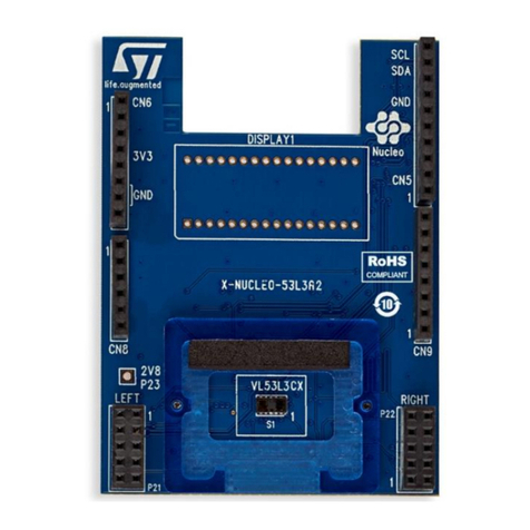
Table 3. Arduino right connector on STM32 Nucleo board
CN number X-NUCLEO-6180A1
expansion board Pin number Pin name MCU pin X-NUCLEO-6180A1 expansion board
function
CN5 digital
SCL 10 D15 PB8 I2C1_SCL
SDA 9 D14 PB9 I2C1_SDA
8 NC
Gnd 7 Gnd Gnd Gnd
GPIO1_L 6 INT_L PA5 Interrupt signal from X-NUCLEO-6180A1 left
breakout plug-in
5 NC
4 NC
3 NC
2 NC
GPIO1_L 1 INT_L* PA9 Interrupt signal from X-NUCLEO-6180A1 left
breakout plug-in (1)
CN9 digital
8 NC
7 NC
6 NC
GPIO1_R 5 INT_R* PB5 Interrupt signal from X-NUCLEO-6180A1 right
breakout plug-in (1)
4 NC
GPIO1_R 3 INT_R PA10 Interrupt signal from X-NUCLEO-6180A1 right
breakout plug-in
2 NC
1 NC
1. These interrupt signals are duplicated, but not used which offers the hardware connection flexibility in case of a conflict on
the MCU interface when the expansion board is used superposed with other expansion boards. In such cases, remove the
0-ohm resistor from the current interrupt and connect it in place of the “do not mount” resistor.
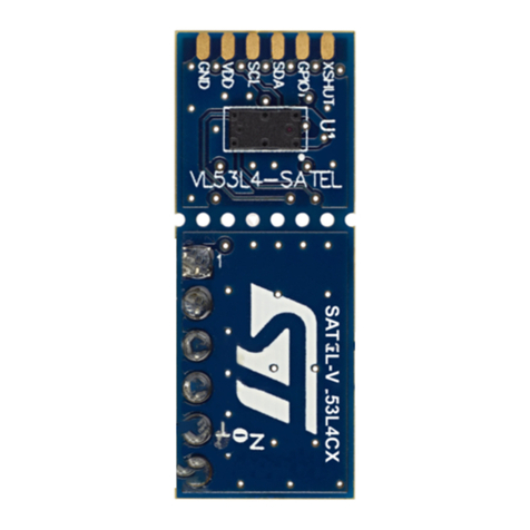
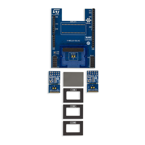
The X-NUCLEO-6180A1 expansion board allows up to three VL6180 breakout boards to be connected to it (see
Figure 4. Connections of VL6180 breakout boards). This allows the development of applications that can control
up to four VL6180 devices.
The I2C bus is shared with the VL6180 on-board I2C bus. The GPIO1 (interrupt) pins and GPIO0 (reset) pins are
separate pins to control each sensor separately.
The GPIO1 signals are output on the Arduino connectors and the GPIO0 signals are controlled through the GPIO
expander device. Refer to Figure 3. Arduino connector layout and Figure 11. X-NUCLEO-6180A1 expansion
board with GPIO expander for detailed connectivity.
UM2657
Board description
UM2657 - Rev 1 page 5/14