ST VL53L1X API User manual

Introduction
The VL53L1X ultra lite driver (ULD) allows a region of interest (ROI) to be selected. This region is defined by default in the
center of the single photon avalanche diode (SPAD) array, but the center of the ROI can be programmed in other locations of
the SPAD array, as explained in this user manual (see figure below).
Figure 1. 27 ° field of view (FoV) down to 15 °
This user manual explains how to configure the ROI of the VL53L1X with a view to moving the FoV so that each range produces
a distance in a different zone. This can be achieved using the software (SW) driver application programming interface in
conjunction with the instructions given in this document.
VL53L1X ultra lite driver multiple zone implementation
UM2555
User manual
UM2555 - Rev 1 - April 2019
For further information contact your local STMicroelectronics sales office.
www.st.com

1Document scope
In this user manual:
• The VL53L1X contains a 16x16 array of SPADs to collect the light.
• "ROI selection" means positioning the reduced sensing area at a selected place on the SPAD array to detect
and measure the distance of the specified area of interest of the external scene.
• "Reduced FoV" means using a reduced number of SPADs for the ROI sensing area to limit the viewingangle
of the sensor device.
• A "multiple zone" provides the ability to change the ROI position after each range.
The selected ROI is defined by a combination of the X and Y axis lengths and the selection of a center of the
rectangle. The ROI must be at least a 4 x 4 region, and the center must be specified so the entire region is within
the SPAD array. The X and Y lengths are specified by the function VL53L1X_SetROI( X, Y) and the center is
specified by the function VL53L1X_SetROICenter( C).
In the figure below, the X length is 6 and the Y is 11. Selection and use of the center SPAD
VL53L1X_SetROICenter( C) is the main focus of this user manual.
ST delivers a software ultra lite driver referred to as the “driver” in this document.
Figure 2. VL53L1X ROI selection with reduced sensing area (blue represents the active sensing area)
UM2555
Document scope
UM2555 - Rev 1 page 2/12

2Acronyms and abbreviations
Table 1. Acronyms and abbreviations
Acronym/abbreviation Definition
FoV field of view
ROI region of interest
SPAD single photon avalanche diode
SW software
ULD ultra lite driver
UM2555
Acronyms and abbreviations
UM2555 - Rev 1 page 3/12

3VL53L1X_SetROICenter()
The function that sets the center of the ROI is VL53L1X_SetROICenter(). This function is included starting with
revision 1.0.3 of the API. For earlier versions, it can be added. It is a very short function. The code is:
VL53L1X_ERROR VL53L1X_SetROICenter(VL53L1_Dev_t dev, uint8_t ROICenter)
{
VL53L1X_ERROR status = 0;
status = VL53L1_WrByte(&dev, ROI_CONFIG__USER_ROI_CENTRE_SPAD, ROICenter);
return status;
}
Where "dev" is the device structure and "ROICenter" is the SPAD to be used at the center.
The prototype is:
/**
* @brief This function programs the center of the ROI (Region of Interest)
* It MUST be called after having called VL53L1X_SetROI
* It allows to change the ROI position
* @param ROICenter: Region of Interest center
*/
VL53L1X_ERROR VL53L1X_SetROICenter(VL53L1_Dev_t dev, uint8_t ROICenter);
UM2555
VL53L1X_SetROICenter()
UM2555 - Rev 1 page 4/12

4SPAD details
4.1 SPAD locations
The photon detector is made up of a 16 x 16 array of SPADs. Each SPAD is identified by a number as shown in
the table below.
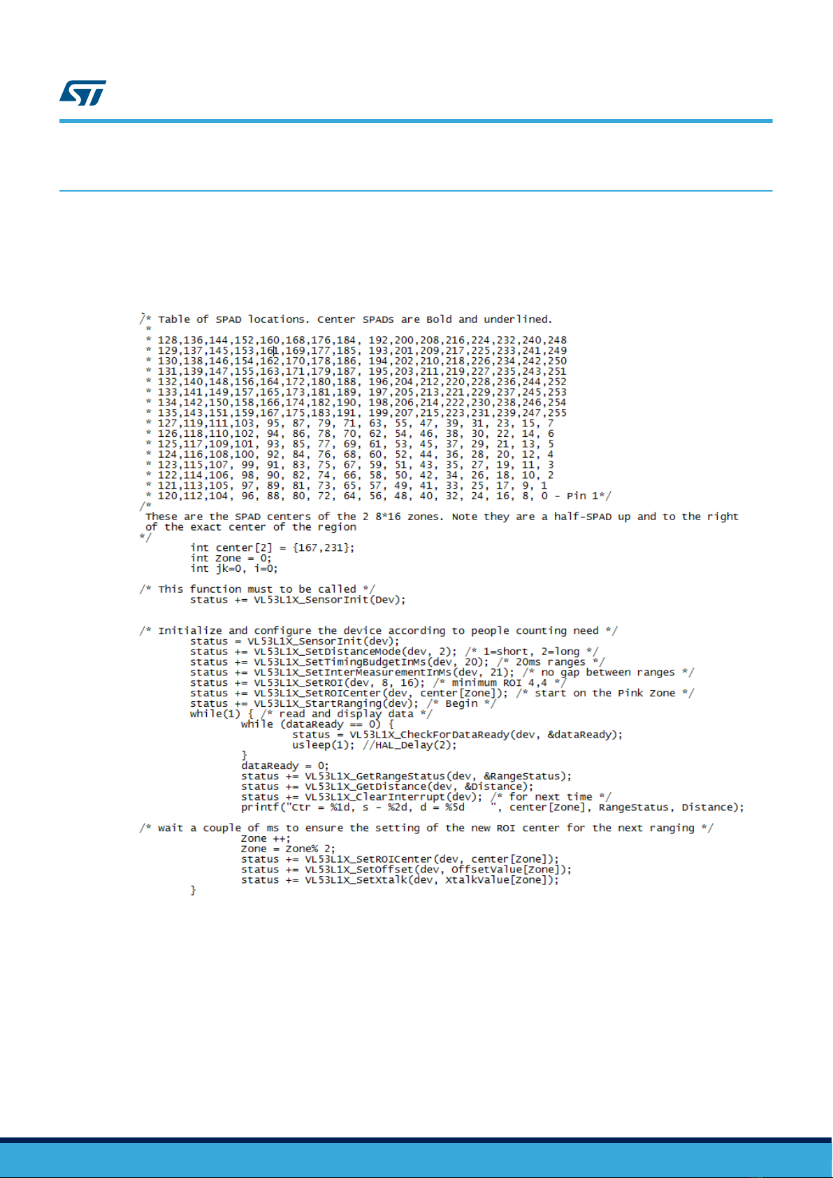
/* Table of SPAD locations. Each SPAD has a number which is not obvious.
*
* 128,136,144,152,160,168,176,184, 192,200,208,216,224,232,240,248
* 129,137,145,153,161,169,177,185, 193,201,209,217,225,233,241,249
* 130,138,146,154,162,170,178,186, 194,202,210,218,226,234,242,250
* 131,139,147,155,163,171,179,187, 195,203,211,219,227,235,243,251
* 132,140,148,156,164,172,180,188, 196,204,212,220,228,236,244,252
* 133,141,149,157,165,173,181,189, 197,205,213,221,229,237,245,253
* 134,142,150,158,166,174,182,190, 198,206,214,222,230,238,246,254
* 135,143,151,159,167,175,183,191, 199,207,215,223,231,239,247,255
* 127,119,111,103, 95, 87, 79, 71, 63, 55, 47, 39, 31, 23, 15, 7
* 126,118,110,102, 94, 86, 78, 70, 62, 54, 46, 38, 30, 22, 14, 6
* 125,117,109,101, 93, 85, 77, 69, 61, 53, 45, 37, 29, 21, 13, 5
* 124,116,108,100, 92, 84, 76, 68, 60, 52, 44, 36, 28, 20, 12, 4
* 123,115,107, 99, 91, 83, 75, 67, 59, 51, 43, 35, 27, 19, 11, 3
* 122,114,106, 98, 90, 82, 74, 66, 58, 50, 42, 34, 26, 18, 10, 2
* 121,113,105, 97, 89, 81, 73, 65, 57, 49, 41, 33, 25, 17, 9, 1
* 120,112,104, 96, 88, 80, 72, 64, 56, 48, 40, 32, 24, 16, 8, 0 /*Pin 1*/
4.2 SPAD selection
The numbering system is easy for the hardware, but not intuitive to people. Select the SPAD number that is
closest to the center of your ROI.
If the center of your region falls between two SPAD numbers, choose the one to the right, or above the center
location.
An ROI center definition example is explained in Section 5.1 Example ROI.
UM2555
SPAD details
UM2555 - Rev 1 page 5/12

5ROI details
5.1 Example ROI
The yellow color in the figure below shows the ROI. The center of this region is 223 (see pink text below). This is
the exact center of the region in the Y direction and it is a half-SPAD right of the exact center in the X direction (as
the X direction contains an even number of SPADs).
Figure 3. SPAD locations
5.2 Error 13
As the input parameter is an unsigned 8-bit value, and the valid range is 0-256, there is no error when the ROI is
set at center. However, when ranging, if the configuration is not correct, the range status returns a 13 error.
The 13 simply means the hardware was not able to select that particular ROI with that specific center location.
This situation happens a lot when moving the ROI as close to the edge as possible. To avoid it, reduce the X or Y
dimensions or move the ROI_Center one SPAD toward the middle.
5.3 Multiple zones
The easy way to implement zones is to choose an X and Y size region and then move the ROI center for each
range. In this way, there is one range for each zone. This user manual assumes a common region size unless
otherwise stated.
UM2555
ROI details
UM2555 - Rev 1 page 6/12

6Timing considerations
There are two basic timing consideration principles:
• Each range completes with the parameters it started with, even if that parameter is changed part way
through the ranging operation.
• Each ranging operation restarts using the timing budget and intermeasurement period currently available
without host intervention.
The multiple zone application uses these two basic principles to ensure the hardware operates correctly.
The application must start ranging and then ensure the new region is programmed PRIOR to the start of the next
range.
UM2555
Timing considerations
UM2555 - Rev 1 page 7/12

7Example code
In the example below, the code ranges using one of two regions: the right region centered about ROI 231 and the
left region centered about ROI 167. Both regions are 8 SPADs wide by 16 SPADs high.
This example can be used as the basis for a system to detect motion to the right or left.
Figure 4. Example code
In this simplified example, there is no error checking. The center [zone] written at the bottom of the loop is the
center of the NEXT range.
UM2555
Example code
UM2555 - Rev 1 page 8/12

8Calibration details
8.1 Offset
For the best accuracy, each zone must be calibrated separately. The procedure is as follows:
• Set the ROI and the ROI center
• Call the calibration function VL53L1X_CalibrateOffset() with a target at a known distance
After each calibration call the function VL53L1X_GetOffset() and retain the value in an array.
When calibration is in progress, and immediately after setting the ROI center, call the function
VL53L1X_SetOffset (), and set the offset calibration for that zone.
8.2 Crosstalk
It is assumed that crosstalk calibration is the same for each zone, but you will need to do some testing to confirm
this in your design.
After testing, if the range result is too short it might be due to crosstalk from the cover glass. The cross talk
calibration can be run for each ROI. Set the ROI, do the crosstalk calibration, read the crosstalk with the
VL53L1X_GetXtalk() and store it.
Every time the ROI is set, set the crosstalk with the function VL53L1X_SetXtalk().
UM2555
Calibration details
UM2555 - Rev 1 page 9/12

Revision history
Table 2. Document revision history
Date Version Changes
16-Apr-2019 1 Initial release
UM2555
UM2555 - Rev 1 page 10/12

Contents
1Document scope ..................................................................2
2Acronyms and abbreviations ......................................................3
3VL53L1X_SetROICenter() ..........................................................4
4SPAD details ......................................................................5
4.1 SPAD locations ................................................................5
4.2 SPAD selection ................................................................5
5ROI details ........................................................................6
5.1 Example ROI ..................................................................6
5.2 Error 13 ......................................................................6
5.3 Multiple zones .................................................................6
6Timing considerations .............................................................7
7Example code .....................................................................8
8Calibration details .................................................................9
8.1 Offset ........................................................................9
8.2 Crosstalk .....................................................................9
Revision history .......................................................................10
Contents ..............................................................................11
UM2555
Contents
UM2555 - Rev 1 page 11/12

IMPORTANT NOTICE – PLEASE READ CAREFULLY
STMicroelectronics NV and its subsidiaries (“ST”) reserve the right to make changes, corrections, enhancements, modifications, and improvements to ST
products and/or to this document at any time without notice. Purchasers should obtain the latest relevant information on ST products before placing orders. ST
products are sold pursuant to ST’s terms and conditions of sale in place at the time of order acknowledgement.
Purchasers are solely responsible for the choice, selection, and use of ST products and ST assumes no liability for application assistance or the design of
Purchasers’ products.
No license, express or implied, to any intellectual property right is granted by ST herein.
Resale of ST products with provisions different from the information set forth herein shall void any warranty granted by ST for such product.
ST and the ST logo are trademarks of ST. For additional information about ST trademarks, please refer to www.st.com/trademarks. All other product or service
names are the property of their respective owners.
Information in this document supersedes and replaces information previously supplied in any prior versions of this document.
© 2019 STMicroelectronics – All rights reserved
UM2555
UM2555 - Rev 1 page 12/12
Other manuals for VL53L1X API
4
Table of contents
Other ST Accessories manuals

ST
ST LIS331AL User manual

ST
ST LPS25H Installation and operating instructions

ST
ST X-CUBE-MEMS1 User manual

ST
ST VL6180X Installation and operating instructions

ST
ST LPS331AP Installation and operating instructions

ST
ST VL53L1X API User manual

ST
ST VL6180 User manual

ST
ST X-NUCLEO-53L3A2 User manual

ST
ST UM2884 User manual

ST
ST VL53L7CH User manual