ST STEVAL-RFPLUG01 User manual

Introduction
The STEVAL-RFPLUG01 evaluation board has been physically tested and validated; it is not for sale.
It is a virtual board intended as a general reference to help you develop your own custom solutions.
It is designed to be used in home automation for Internet of Things (IoT) applications and embeds the core functionality required
for a secure communication.
It has the capability of wireless connectivity over sub-GHz or BLE and can also measure energy parameters such as power,
voltage, current and power factor via the STPM32 metering IC.
You can use the Triac to control the load, and the isolated USB port and dual EEPROM (M24LR) to communicate with GUI and
NFC.
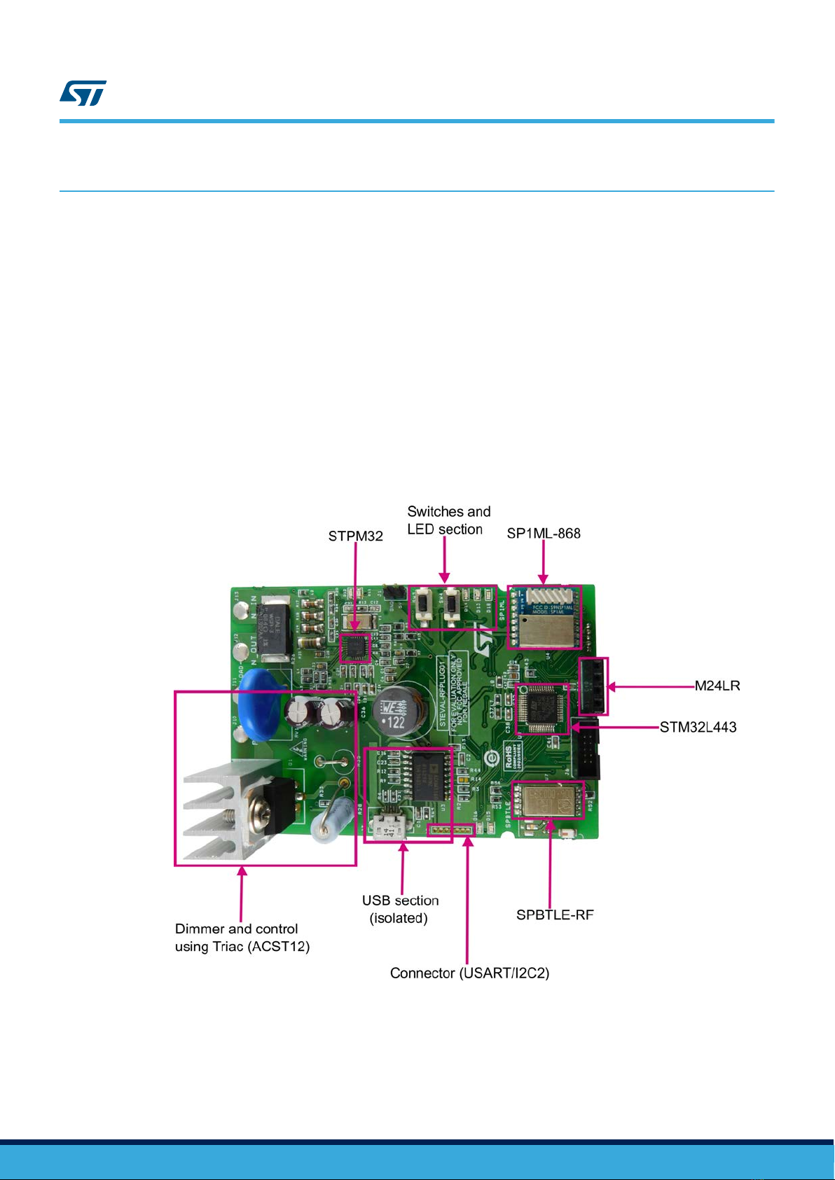
Figure 1. STEVAL-RFPLUG01 evaluation board
Getting started with the STEVAL-RFPLUG01 RF smart plug based on
STM32L443
UM2366
User manual
UM2366 - Rev 1 - February 2018
For further information contact your local STMicroelectronics sales office.
www.st.com
1Getting started
1.1 Board main components
The STEVAL-RFPLUG01 evaluation board embeds the following components by ST:
•STM32L443CCT6 (Ultra-low power microcontroller with FPU ARM® Cortex®-M4 MCU 80 MHz)
•M24LR (4-Kbit dynamic NFC/RFID tag with password protection )
•STPM32 (ASSP for metering applications with up to four independent 24-bit 2nd order sigma-delta ADCs)
•LD39050 (500 mA low quiescent current and low noise voltage regulator)
•SPBTLE-RF (Very low power module for Bluetooth Smart v4.1 )
•SP1ML-868 (Sub 1 GHz module)
•VIPER06XS (VIPerPlus family: energy saving high voltage converter for direct feedback)
•STTH110RL (High voltage ultra-fast rectifier diode)
•ACST12 (Overvoltage protected AC switch)
Figure 2. STEVAL-RFPLUG01 evalution board main components
1.2 Key features
• Wireless smart plug design with wireless connectivity
• Bluetooth low energy (BLE) 4.1 connectivity for control and metering panel
• Smartphone connectivity for energy consumption dashboard and control of appliances
UM2366
Getting started
UM2366 - Rev 1 page 2/21
• Sub-GHz 868 MHz connectivity for remote control based on the SP1ML certified module
•Dimming to control loads such as AC induction fan speed, heaters and incandescent lamps
•Scheduling to set the time to switch the load on or off
•NFC interface to configure the design and store the logs
•Isolated USB interface for GUI and calibration
•Rated voltage of 240 VAC
• Rated current of 12 A (typ.)
• Power rating up to 2400 W/12 Amps
• Plug power consumption of 0.7 W (max.)
1.3 Package contents
The STEVAL-RFPLUG01 evaluation board package includes:
•Hardware
–STEVAL-RFPLUG01
•Software
– Android application
– GUI to measure STPM32 parameters
•Documentation
– Schematics, Gerber files and bill of materials
•Microcontroller firmware
– Pre-programmed STM32L443CCT6 device soldered on the evaluation board
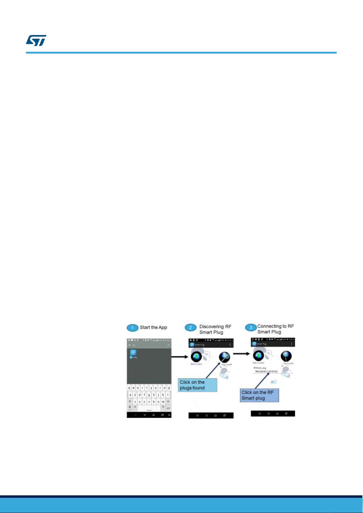
1.4 Board setup
Step 1. Connect the board to AC supply
Step 2. Connect the load to the STEVAL-RFPLUG01 evaluation board
Step 3. Search for the device in the Android application
Step 4. Connect your device
Figure 3. Connecting the device to the Android application
Step 5. Control the device via the app.
UM2366
Package contents
UM2366 - Rev 1 page 3/21
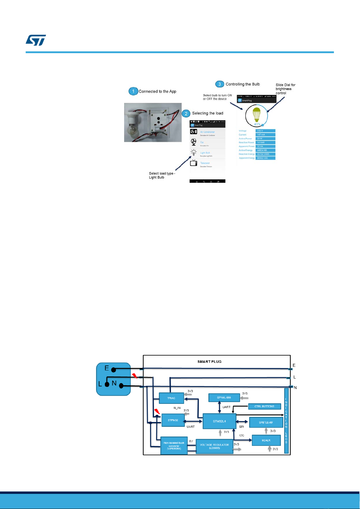
Figure 4. Controlling the device
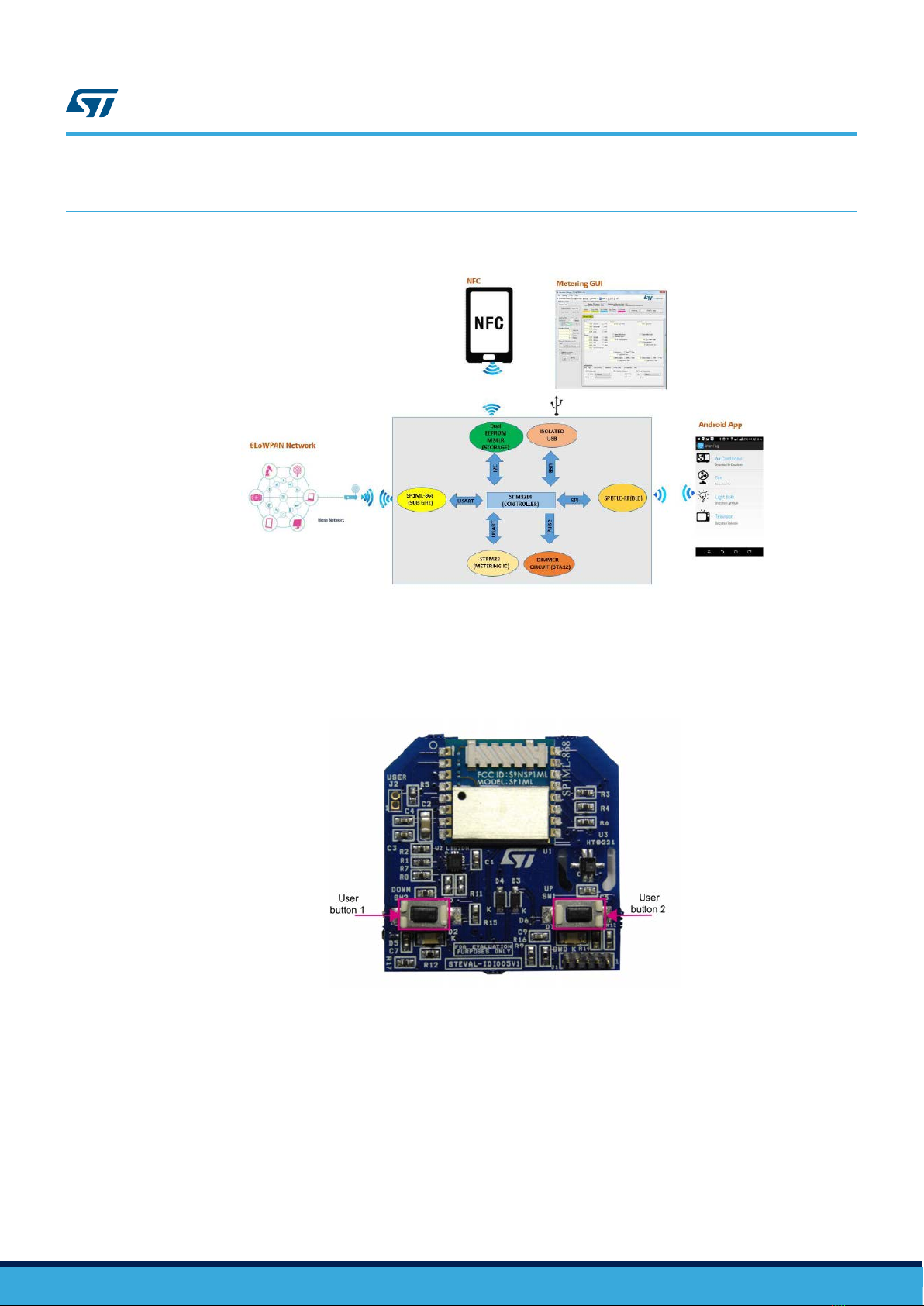
1.5 System architecture
The STEVAL-RFPLUG01 has two modes: in the first mode, the device acts as a BLE peripheral to control and
monitor the system; in the second mode, the device is a manufacturer-specific beacon advertising its metering
parameters so that multiple Android devices can monitor the plug.
The system architecture is based on the STM32L443CCT6 microcontroller, featuring ARM® Cortex®-M4 core. It
mainly features crystal-less USB, 100 DMIPS and operating voltage from 1.71 to 3.6 V.
The Triac acts as a switch to to turn the load on/off and also to control the phase for dimming.
The Android application sends commands to the SPBTLE-RF via BLE. Commands received are sent to the
microcontroller through the SPI interface for further processing.
The system is powered through a non-isolated buck converter designed using VIPER06XS.
It is used with PWM operation at 30 kHz with frequency jittering for lower EMI, having standby power <30 mW
(ideal for applications where large current is not needed and small form factor is required).
In the STEVAL-RFPLUG01 evaluation board, the supply output is set at 4.5 V.
The LD39050, having output voltage and current of 3.3 V and 500 mA, is used to power all the analog and digital
sections up.
The STPM32 measures the electrical parameters and sends them to the microcontroller over USART. The
Android app displays the results on the metering panel.
M24LR is used to store the reading for maximum demand and for BLE paring.
Figure 5. STEVAL-RFPLUG01 block diagram
UM2366
System architecture
UM2366 - Rev 1 page 4/21
Triac is a three-terminal component used to control the current and switch AC in various electrical system
applications.
It can also change the duty cycle of the AC voltage applied to the lights/load controlled.
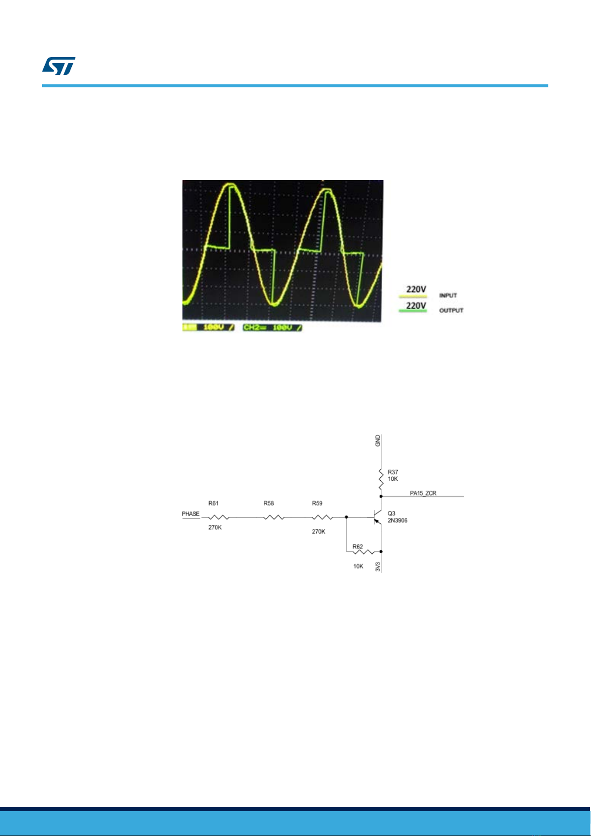
Figure 6. AC voltage status at 50% duty cycle (controlled by Triac)
Zero crossing detection (ZCD) is used to dim the reference point to fire the Triac accordingly. This circuit has 3
resistors of 270 K (R35, R36 and R37), connected to the AC line phase; the resistors lower the result voltage on
the basis of a PNP transistor embedding a pull-up resistor (R41).
When the voltage at the base goes below a certain treshold, the operating voltage transistor switches to output
low as shown below.
Figure 7. ZCD schematic diagram
UM2366
System architecture
UM2366 - Rev 1 page 5/21

Figure 8. ZCD output waveform
1.6 State machine
This state machine represents:
•BLE profiles initialization
– Initialization of all peripherals
– Initialization of MAC (GAP Role-Device is in Peripheral Role, GATT-Device is in Server mode)
– Initialization of Services:
◦ Notification (to send metering data to the Android application) and Write (to get commands form
the app)
◦ Authentication (to bond the device) and TX Power Set (to set the output power level)
•USB plugged
– Polling allows the device to do metering when the USB is plugged
– Interrupt is used otherwise
•USB Packet Process sends data to the USB during operational state at the rate of 1 msec.
•BLE Packet Process manages and puts BLE packets in a queue with data and commands to be sent to
SPBTLE-RF through the SPI Interface.
•Triac interrupt service routine (ISR) manages the firing time of the Triac according to the received control
data packets.
Figure 9. State machine
UM2366
State machine
UM2366 - Rev 1 page 6/21
2User interface
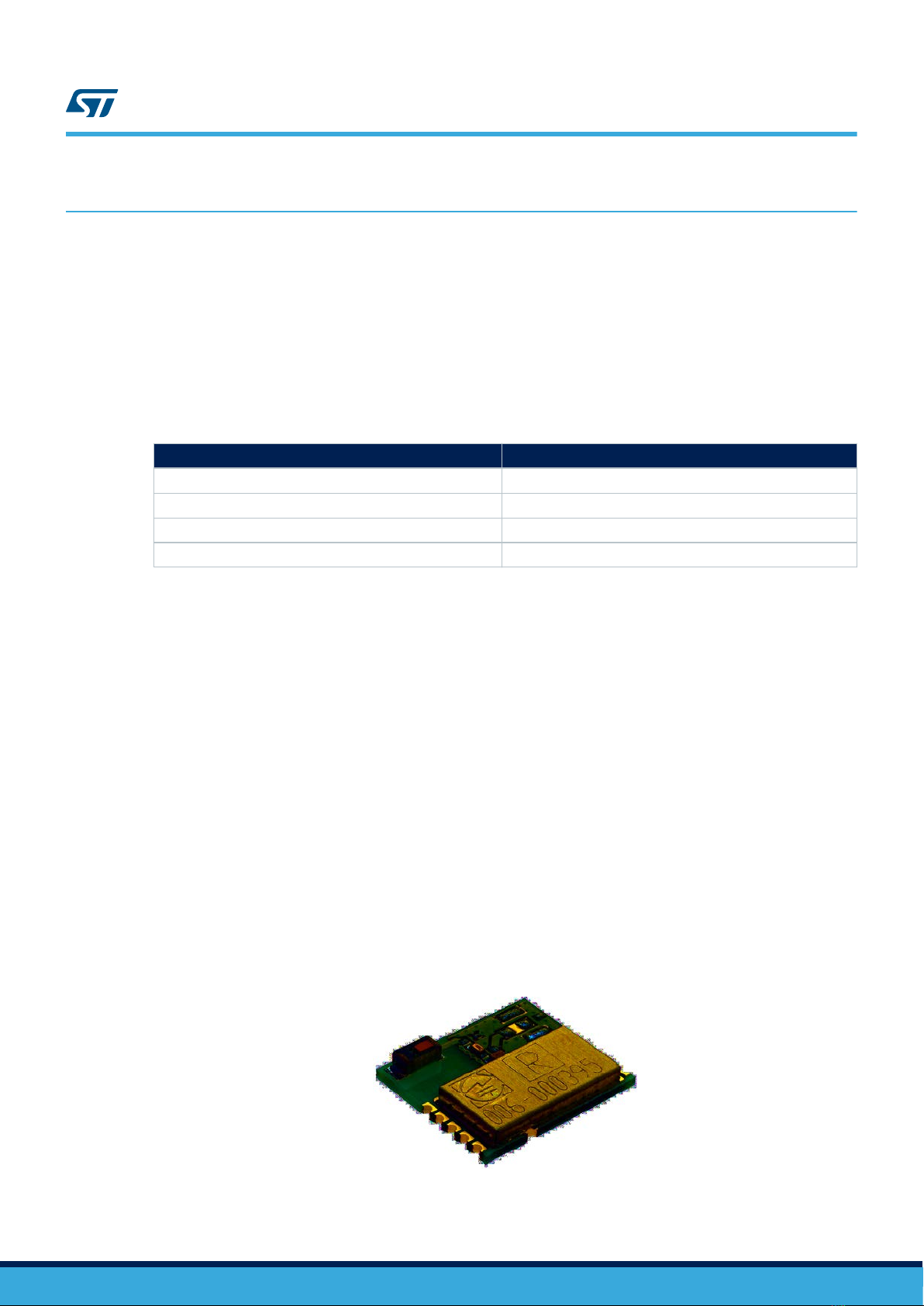
Figure 10. STEVAL-RFPLUG01 user interface
The STEVAL-IDI005V1 evaluation board controls the dimming and turning the load on or off, via two buttons:
• User button 1 decreases the brightness level or turns the load off;
• User button 2 increases the brightness level or turns the load on.
Figure 11. STEVAL-IDI005V1 user buttons
UM2366
User interface
UM2366 - Rev 1 page 7/21
3Hardware description
3.1 STM32L443CCT6
The STM32L443CCT6 is an ultra-low power microcontroller with FPU ARM® Cortex®-M4.
It mainly features: crystal-less USB, 100 DMIPS and operating voltage from 1.71 to 3.6 V.
It has 12-bit ADC (5 Msps), an internal voltage reference buffer, a low-power RTC, one general-purpose 32-bit
timer, one 16-bit PWM timer, four general-purpose 16-bit timers and two 16-bit low-power timers.
Table 1. STM32L443CCT6 details
Feature Description
Order Code STM32L443CCT6
Package LQFP-48
Flash – Kbytes 256
Operating voltage 1.8 to 3.6 V
3.2 STPM32
The STPM32 is an ASSP designed for high accuracy measurement of power and energies in power systems.
It is a mixed signal IC family consisting of an analog and a digital section.
The analog section consists of up to two programmable gain low-noise low-offset amplifiers and up to four 2nd
order 24-bit sigma-delta ADCs, two bandgap voltage references with independent temperature compensation, a
low drop voltage regulator and DC buffers.
The digital section consists of digital filtering stage, a hard-wired DSP, DFE to the input and a serial
communication interface (UART or SPI).
3.3 SPBTLE-RF
The SPBTLE-RF is Bluetooth 4.1 complaint network processor with ARM®Cortex®-M0 core which has very low
power consumption.
The entire Bluetooth smart stack and protocols are embedded in this module. The external host application
processor, where the application resides, is connected to the SPBTLE-RF module through a standard SPI
interface.
The module can be powered directly with a standard 3 V coin cell battery, a pair of AAA batteries or any power
source from 1.7 to 3.6 V.
Figure 12. SPBTLE-RF module
UM2366
Hardware description
UM2366 - Rev 1 page 8/21

3.4 SP1ML-868
The SP1ML-868 is a ultra-low power and fully integrated RF module operating in the 868 MHz SRD ISM band.
The module is compact-size, integrating an on-board antenna with easy-to-use interface, allowing users to easily
add wireless connectivity in designs without requiring in-depth RF experience.
The module is based on the SPIRIT1 RF sub-GHz transceiver (with integrated SMPS), STM32L1 microcontroller,
integrated filter/balun and chip antenna.
The UART host interface let you easily connect to an external microcontroller with a standard firmware, allowing
AT commands to facilitate RF configuration, data transmission and reception, using simple point-to-point
communication.
Figure 13. SP1ML-868 module
UM2366
SP1ML-868
UM2366 - Rev 1 page 9/21
4Board layout
Figure 14. STEVAL-RFPLUG01 top layer
UM2366
Board layout
UM2366 - Rev 1 page 10/21
Table of contents
Other ST Accessories manuals


