ST STEVAL-ISB044V1 User manual

October 2017
DocID031141 Rev 1
1/57
www.st.com
UM2301
User manual
Getting started with the Qi MP-A10 wireless charger Tx
evaluation board based on STWBC-EP
Introduction
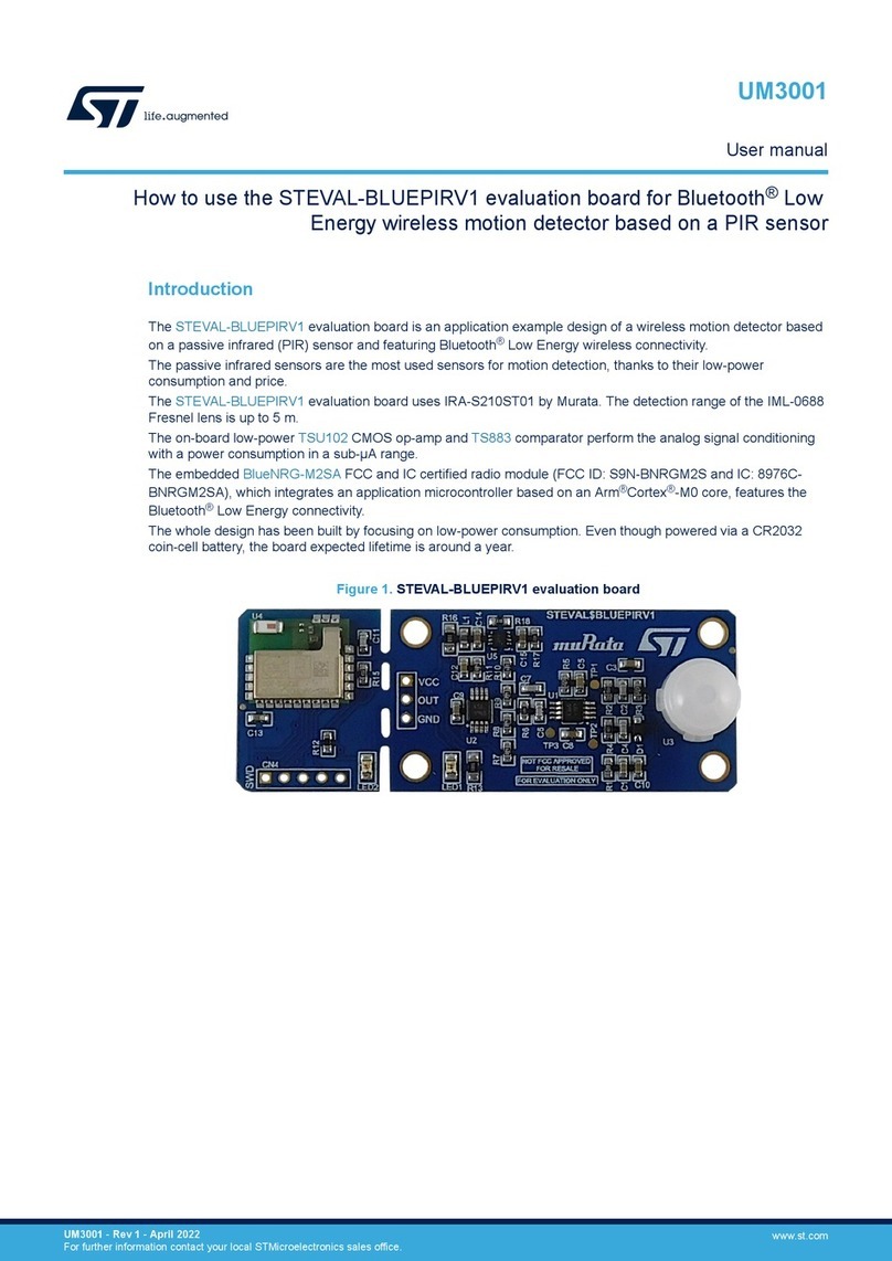
The STEVAL-ISB044V1 wireless power transmitter evaluation board is based on the MP-A10 (CR419)
wireless power consortium (WPC) standard version 1.2.3 and supports FOD (foreign object detection).
The transmitter supports all Qi-compatible receivers (such as those in Qi- enabled mobile phones) as
well as resistive or capacitive modulation receivers.
In accordance with the Qi-MPA10 topology, the STEVAL-ISB044V1 supports a 5-13 V input voltage and
a half-bridge stage with bridge voltage/frequency control.
The evaluation board is based on the STWBC- EP controller which integrates all the functions required
to drive and monitor the transmitter, and controls the bridge voltage built in boost topology.
The STWBC-EP supports UART connectivity to a PC and, thanks to the STEVAL-ISB044V1 graphical
interface, monitors the transmitter behavior in real-time.
The STEVAL-ISB044V1 reference design provides a complete kit which includes the STWBC-EP,
firmware, layout based on cost- effective 2-layer PCB, graphical interfaces and tools.
Figure 1: STEVAL-ISB044V1 evaluation board

Contents
UM2301
2/57
DocID031141 Rev 1
Contents
1Getting started ................................................................................. 7
1.1 System requirements........................................................................7
1.2 Package contents..............................................................................7
2Hardware description and setup .................................................... 8
2.1 System block diagram.......................................................................8
2.2 STEVAL-ISB044V1 wireless transmitter board overview..................8
2.3 STWBC-EP pinout and pin description ...........................................11
3Download procedure ..................................................................... 13
3.1 STSW-STWBCGUI software installation.........................................13
3.2 Firmware download via STSW-STWBCGUI ...................................14
3.2.1 Download procedure with a new chip (never been programmed) ... 14
3.2.2 Firmware upgrade procedure (chip already programmed)............... 17
3.3 Erasing firmware procedure using STVP ........................................18
3.3.1 Requirements ................................................................................... 18
3.3.2 Procedure......................................................................................... 19
3.4 Firmware download with command line..........................................20
3.4.1 Firmware download with written chip ............................................... 20
3.4.2 Firmware download with blank chip ................................................. 21
3.5 STVP file creation ...........................................................................21
3.6 Firmware download with STVP.......................................................23
4Evaluation equipment setup ......................................................... 26
4.1 External power supply.....................................................................26
4.2 USB charger....................................................................................27
4.3 UART configuration.........................................................................27
5GUI and evaluation procedure ...................................................... 29
5.1 Status LEDs....................................................................................33
5.2 Test procedure for board calibration ...............................................33
5.2.1 Presence detection calibration procedure........................................ 34
5.2.2 QFOD calibration procedure ............................................................ 35
5.3 Efficiency.........................................................................................36
5.4 Stand-by consumption ....................................................................37
6Schematic diagram ........................................................................ 38
7Bill of materials .............................................................................. 45

UM2301
Contents
DocID031141 Rev 1
3/57
8Board assembly and layout .......................................................... 48
8.1 Power signals (BOOST, GND, LC) .................................................49
8.2 EMI components.............................................................................52
8.3 STWBC-EP layout...........................................................................53
8.4 Current sensing and demodulation .................................................54
9References ..................................................................................... 55
10 Revision history ............................................................................ 56

List of tables
UM2301
4/57
DocID031141 Rev 1
List of tables
Table 1: STEVAL-ISB044V1 electrical performance: input characteristics................................................9
Table 2: STEVAL-ISB044V1 electrical performance: system characteristics ............................................9
Table 3: Connector description.................................................................................................................10
Table 4: Test point description..................................................................................................................10
Table 5: STWBC-EP pin description.........................................................................................................12
Table 6: STEVAL-ISB044V1 bill of materials ...........................................................................................45
Table 7: Document revision history ..........................................................................................................56

UM2301
List of figures
DocID031141 Rev 1
5/57
List of figures
Figure 1: STEVAL-ISB044V1 evaluation board..........................................................................................1
Figure 2: STWBC-EP block diagram ..........................................................................................................8
Figure 3: STEVAL-ISB044V1 evaluation board: connectors, LEDs and test points ..................................9
Figure 4: STEVAL-ISB044V1 evaluation board: power supply selection.................................................10
Figure 5: STWBC-EP pinout in MP-A10 configuration.............................................................................11
Figure 6: STSW-STWBCGUI installation file............................................................................................13
Figure 7: Windows Device Manager: COM port selection........................................................................13
Figure 8: STSW-STWBCGUI start screen................................................................................................14
Figure 9: Dongle connection.....................................................................................................................15
Figure 10: Firmware download via STSW-STWBCGUI ...........................................................................15
Figure 11: Firmware file selection message.............................................................................................16
Figure 12: Firmware file selection.............................................................................................................16
Figure 13: Power on message..................................................................................................................16
Figure 14: USB-to-UART dongle to STEVAL-ISB044V1 connection .......................................................17
Figure 15: DOS window: download in progress .......................................................................................17
Figure 16: STVP configuration..................................................................................................................18
Figure 17: STEVAL-ISB044V1 evaluation board: ST-LINK connection ...................................................19
Figure 18: STVP core selection................................................................................................................19
Figure 19: STVP download.......................................................................................................................20
Figure 20: STVP wrong device selected alert ..........................................................................................20
Figure 21: STVP incompatibility device action query ...............................................................................20
Figure 22: STSW-STWBCGUI command line..........................................................................................21
Figure 23: STSW-STWBCGUI command line with blank chip .................................................................21
Figure 24: STSW-STWBCGUI: convert CAB to STVP files .....................................................................22
Figure 25: Selecting the CAB file to be converted....................................................................................22
Figure 26: STVP project file name............................................................................................................23
Figure 27: STVP files created...................................................................................................................23
Figure 28: STVP file selection ..................................................................................................................24
Figure 29: STEVAL-ISB044V1 evaluation board: test setup configuration..............................................26
Figure 30: STEVAL-ISB044V1 evaluation board: external power supply connection..............................26
Figure 31: STEVAL-ISB044V1 evaluation board: external power supply connection..............................27
Figure 32: STEVAL-ISB044V1 evaluation board: UART connection .......................................................28
Figure 33: STSW-STWBCGUI: object detected and charge in progress.................................................29
Figure 34: STSW-STWBCGUI: Qi protocol window.................................................................................30
Figure 35: STSW-STWBCGUI: Qi monitor window..................................................................................30
Figure 36: STSW-STWBCGUI: Parameters window................................................................................31
Figure 37: STSW-STWBCGUI: modified parameters...............................................................................31
Figure 38: STSW-STWBCGUI: saving modified parameters (Dump to bin) ............................................32
Figure 39: STSW-STWBCGUI: bin file backup ........................................................................................32
Figure 40: STSW-STWBCGUI: CAB file patch button..............................................................................33
Figure 41: STSW-STWBCGUI: start auto-calibration...............................................................................34
Figure 42: STSW-STWBCGUI: presence detection test..........................................................................34
Figure 43: STSW-STWBCGUI: test result................................................................................................35
Figure 44: STSW-STWBCGUI: QFOD test ..............................................................................................35
Figure 45: STSW-STWBCGUI: QFOD test result ....................................................................................36
Figure 46: Efficiency setup .......................................................................................................................36
Figure 47: STEVAL-ISB044V1 evaluation board: efficiency performance with MP1B Rx .......................37
Figure 48: STEVAL-ISB044V1 circuit schematic (1 of 8).........................................................................38
Figure 49: STEVAL-ISB044V1 circuit schematic (2 of 8).........................................................................39
Figure 50: STEVAL-ISB044V1 circuit schematic (3 of 8).........................................................................40
Figure 51: STEVAL-ISB044V1 circuit schematic (4 of 8).........................................................................41
Figure 52: STEVAL-ISB044V1 circuit schematic (5 of 8).........................................................................42
Figure 53: STEVAL-ISB044V1 circuit schematic (6 of 8).........................................................................43
List of figures
UM2301
6/57
DocID031141 Rev 1
Figure 54: STEVAL-ISB044V1 circuit schematic (7 of 8).........................................................................43
Figure 55: STEVAL-ISB044V1 circuit schematic (8 of 8).........................................................................44
Figure 56: STEVAL-ISB044V1 evaluation board: functional block assembly ..........................................48
Figure 57: STEVAL-ISB044V1 evaluation board: power signal routing ...................................................49
Figure 58: STEVAL-ISB044V1 evaluation board: ground plan ................................................................49
Figure 59: STEVAL-ISB044V1 evaluation board: DC-DC boost routing details.......................................50
Figure 60: STEVAL-ISB044V1 evaluation board: power GND routing details.........................................50
Figure 61: STEVAL-ISB044V1 evaluation board: bridge node routing details.........................................51
Figure 62: STEVAL-ISB044V1 evaluation board: shunt resistor routing details ......................................51
Figure 63: STEVAL-ISB044V1 evaluation board: EMI components (1 of 2)............................................52
Figure 64: STEVAL-ISB044V1 evaluation board: EMI components (2 of 2)............................................52
Figure 65: STWBC-EP digital controller layout.........................................................................................53
Figure 66: STEVAL-ISB044V1 evaluation board: current sensing...........................................................54
Figure 67: STEVAL-ISB044V1 evaluation board: current demodulation..................................................54

UM2301
Getting started
DocID031141 Rev 1
7/57
1 Getting started
1.1 System requirements
To use the STEVAL-ISB044V1 evaluation board with the graphical user interface (GUI),
you need:
a PC with Microsoft®Windows®operating system (XP or later versions)
NET Framework 4
a USB-to-UART cable to connect the board to the PC.
1.2 Package contents
Hardware:
a STEVAL-ISB044V1 evaluation board
ST-LINK/V2 in-circuit debugger/programmer with single wire interface module
(SWIM), available for download on www.st.com
a USB-to-UART interface dongle with a micro-USB cable for board debug and
GUI use
Software:
ST-LINK USB driver
STVP programming software (integrated in ST_toolset available on www.st.com)
FTDI VCP driver (http://www.ftdichip.com/Drivers/VCP.htm)
PC GUI installation package

Hardware description and setup
UM2301
8/57
DocID031141 Rev 1
2 Hardware description and setup
2.1 System block diagram
Figure 2: STWBC-EP block diagram
2.2 STEVAL-ISB044V1 wireless transmitter board overview
The STEVAL-ISB044V1 evaluation board features:
STWBC-EP digital controller
15 W output power
Qi MP-A10 reference design
WPC Qi1.2.3 standard compliant
Robust demodulation algorithm, with triple path (V, I, f)
Foreign object detection (FOD)
Accurate power control
Active presence detection
UART protocol to control and monitor the system
Complete reference design (evaluation board, IC, firmware and tools)
2-layer PCB for easy design
Flash memory-based
RoHS compliant

UM2301
Hardware description and setup
DocID031141 Rev 1
9/57
Table 1: STEVAL-ISB044V1 electrical performance: input characteristics
Parameter
Input
characteristics
Min.
Typ.
Max.
Unit
Notes and conditions
Vin
Input voltage
5
12
13
V
Iin
Input current
1.6
2
A
Vin nominal, Iout = max. on MP1B
Rx
Input no-load current
mA
Input stand-by
current
1.4
mA
At typical voltage
Table 2: STEVAL-ISB044V1 electrical performance: system characteristics
Parameter
Input characteristics
Min.
Typ.
Max.
Unit
Notes and conditions
Fs
Switching frequency
110
180
kHz
Decrease with load
Duty cycle
Duty cycle modulation
5
50
%
Duty cycle
ƞ
Full load efficiency
80
%
Vin= 12 V, P Out Rx = 15 W
Figure 3: STEVAL-ISB044V1 evaluation board: connectors, LEDs and test points

Hardware description and setup
UM2301
10/57
DocID031141 Rev 1
Figure 4: STEVAL-ISB044V1 evaluation board: power supply selection
Table 3: Connector description
Connector reference
Description
J100
DC power jack connector
J101
Power/QC USB connector link
J500
SWIM connector used for the download
J501
UART jack connector used for the GUI
J700
Quick charge USB connector
Table 4: Test point description
Test point reference
Signal
Description
TP100
12 V
12 V power supply connection
TP101
GND
GND power connection
TP102
VIN
Input voltage
TP103
VDD_STWBC
4.5V LDO output voltage
TP200
VDCDC
Boost output voltage
TP301
ISENSE
Current measurement
TP302
GND
Power GND connection (Rsense)
TP303
VRSENSE
Rsense resistor voltage
TP304
Wireless charging coil connection
TP305
Wireless charging coil connection

UM2301
Hardware description and setup
DocID031141 Rev 1
11/57
Test point reference
Signal
Description
TP400
SYMBOL_DETECT
Symbol detector
TP501
I2C_SCL
STWBC I²C signal
TP502
I2C_SDA
STWBC I²C signal
TP503
USB_DP
STWBC UART Rx signal
TP504
USB_DM
STWBC UART Tx signal
TP506
GPIO_0
STWBC GPIO signal used for LEDs
TP507
GND
Ground
TP508
CURRENT_DEMOD
Symbol detector
TP509
QC_IO
Quick charge circuit signal
TP510
GND
Ground
TP511
GND
Ground
2.3 STWBC-EP pinout and pin description
The STWBC-EP is a multifunction device that can support several wireless
charging architectures.
This section shows the STWBC-EP pinout when the MP-A10 configuration is used.
Figure 5: STWBC-EP pinout in MP-A10 configuration

Hardware description and setup
UM2301
12/57
DocID031141 Rev 1
Table 5: STWBC-EP pin description
Pin
number
Pin name
Pin
type
Firmware description
1
UART_RX
DI
Uart RX link on USB debug connector
2
PWM_QFOD
DO
PWM dedicated to QFOD circuit
3
I2C_SDA
I2C_SDA
4
I2C_SCL
I2C_SCL
5
DNBL
DO
Output driver for Low side branch
6
LED
DO
Digital output for light indicators
7
QC_IO
DO
Quick charge circuit signal
8
CMP_OUT_V
AI
Boost output voltage sensing
9
CS_CMP
AI
Boost current sensing
10
DCDC_DAC_REF
AI
DAC reference value for Boost output voltage
11
WAVE_SNS
AI
Symbol detector based on delta frequency
12
CURRENT_DEMOD
AI
Current demodulation
13
VDDA
PS
Analog power supply
14
VSSA
PS
Analog ground
15
TANK_VOLTAGE
AI
Analog input to measure the LC voltage (power calculation)
16
VTARGET
AI
Boost voltage measurement
17
QFOD_ADC
AI
High sensitivity peak voltage detector used for Quality Factor
measurement
18
COIL_TEMP
AI
Analog input for temperature measurement. The input is
connected to external NTC biased to VDD_STWBC
19
ISENSE
AI
Analog input to measure the current flowing into the power
bridge
20
VMAIN
AI
Analog input to measure the main power supply
21
DCDC_DRV
DO
DCDC boost PWM drive
22
DEMAGNET
DI
Boost demagnetization
23
SYMBOL_DETECT
DI
Voltage demodulation
24
DCDC_DAC
DO
Boost PWM output DAC (setting the CPP3 comparator voltage
reference)
25
UPBL
DO
Output driver for high side branch
26
DNBL_FB
Used for hardware PWM programmation
27
SWIM
DIO
Digital IO for debug interface
28
NRST
DI
Reset
29
VDD
PS
Digital and I/O power supply
30
VSS
PS
Digital and I/O ground
31
VOUT
Supply
Internal LDO output
32
UART_TX
DO
Uart TX link on USB debug connector
AlI analog inputs are VDD compliant but can be used only between 0 and 1.2 V.

UM2301
Download procedure
DocID031141 Rev 1
13/57
3 Download procedure
To download the firmware to the board, the user has to install the GUI software which
allows a complete board monitoring via UART signals. Thus, to use the STSW-
STWBCGUI, UART signals must be accessible.
In case of board issues, ST-LINK and STVP software can be installed to erase the
STWBC-EP Flash memory.
3.1 STSW-STWBCGUI software installation
1
Install the GUI by launching the STWBC_GUI_Setup.msi installation file
Figure 6: STSW-STWBCGUI installation file
2
Connect the wireless power transmitter board to the PC via the USB-to-UART
connection on J501 UART connector
3
Check Windows Device Manager to identify the correct port number and select the
appropriate USB serial COM port
Figure 7: Windows Device Manager: COM port selection
4
Enter a specific COM port number (if not listed in the selection window) in the
Special text box (e.g.,“COM12” or the specific syntax “\\.\COM12”)
If the GUI is switched off, ensure that the COM port is not used on your computer.

Download procedure
UM2301
14/57
DocID031141 Rev 1
Otherwise, try another USB port.
Figure 8: STSW-STWBCGUI start screen
5
Press “OK”.
The GUI is ready to run.
3.2 Firmware download via STSW-STWBCGUI
The following sections describe the firmware download through the UART connector via
STSW-STWBCGUI.
The download contains 3 files incorporated in a single cabfile.
3.2.1 Download procedure with a new chip (never been programmed)
If the chip has never been programmed, the download mode is enabled by default.
1
Connect the USB-to-UART dongle to the computer.
Do not connect the transmitter board for the moment.

UM2301
Download procedure
DocID031141 Rev 1
15/57
Figure 9: Dongle connection
2
From the GUI, select Load FW to board from the setup menu.
Figure 10: Firmware download via STSW-STWBCGUI

Download procedure
UM2301
16/57
DocID031141 Rev 1
3
As prompted, select the CAB file containing the firmware to download
Figure 11: Firmware file selection message
Figure 12: Firmware file selection
4
Supply the board with 12 V and keep it powered.
Figure 13: Power on message
5
When the DOS window appears, connect the transmitter board to the dongle using
a micro-USB cable.
Take care to connect it to the USB debug connector J501
on the opposite side of the power supply connection.

UM2301
Download procedure
DocID031141 Rev 1
17/57
Figure 14: USB-to-UART dongle to STEVAL-ISB044V1 connection
6
Follow the download progress in the DOS window and power the board off when
prompted.
Figure 15: DOS window: download in progress
3.2.2 Firmware upgrade procedure (chip already programmed)
If a chip has already been programmed with the firmware, the download mode is disabled
and special command needs to be sent to STWBC-EP to enable the download mode.
1
2
3
Supply the transmitter board via a power supply set to12 V.
Connect the USB-to-UART dongle to the transmitter board.
The STWBC-EP UART Rx/Tx signals are accessible on the transmitter board J501
connector, respectively on USB_DP and USB_DM (see Figure 14: "USB-to-UART
dongle to STEVAL-ISB044V1 connection").

Download procedure
UM2301
18/57
DocID031141 Rev 1
4
5
6
7
From the STSW-STWBCGUI, select Load FW to board in the setup menu (see
Figure 10: "Firmware download via STSW-STWBCGUI").
As prompted, select the CAB file containing the firmware to download (see
Figure 11: "Firmware file selection message").
As prompted, power the board on and keep it powered.
Follow the download progress in the DOS window and power the board off when
prompted (see Figure 15: "DOS window: download in progress").
In case of problems in downloading the firmware through UART (for example,
firmware corruption during update), refer to the following section.
3.3 Erasing firmware procedure using STVP
3.3.1 Requirements
To start the firmware erasing procedure using STVP, you have to install on your PC:
ST-LINK USB driver
STVP programming tool (available at www.st.com)
ST-LINK hardware tools
You also need to configure STVP as shown below.
Figure 16: STVP configuration

UM2301
Download procedure
DocID031141 Rev 1
19/57
3.3.2 Procedure
1
Power the target off.
2
Power the target on.
3
Connect ST-LINK circuit to the PC via USB.
4
Connect the ST-LINK–SWIM cable to the target.
Pay special attention in connecting the SWIM cable to the transmitter
board correctly, as shown below.
Figure 17: STEVAL-ISB044V1 evaluation board: ST-LINK connection
5
Launch STVP software.
6
Select STM8AF6166 as core.
Figure 18: STVP core selection
Do not upload any program into the STVP RAM area, as all bits will be
erased (load 00 00 00).

Download procedure
UM2301
20/57
DocID031141 Rev 1
7
Transfer the ”00 00” to the STWBC-EP via the SWIM interface using the appropriate
push button.
Figure 19: STVP download
8
Click OK if a “wrong device selected” alert appears.
Figure 20: STVP wrong device selected alert
9
Click YES if “An incompatibility has been found with this device” alert appears.
Figure 21: STVP incompatibility device action query
After this operation, the programming procedure starts. At completion, the STVP informs the
user that the program is loaded and verified.
< PROGRAM MEMORY programming completed.
> Verifying PROGRAM MEMORY area...
< PROGRAM MEMORY successfully verified.
10
Exit from the STVP program.
11
Disconnect SWIM.
12
Remove power supply from the STEVAL-ISB044V1 transmitter board.
13
Retry the UART download procedure if necessary.
3.4 Firmware download with command line
3.4.1 Firmware download with written chip
1
Ensure a dedicated directory has the following files:
STWBC_Loader.exe
stwbc_loader_not_empty.bat
enable_boot.bin
“firmware version“.cab
Table of contents
Other ST Motherboard manuals

ST
ST UM0804 User manual

ST
ST STM32100B-EVAL User manual

ST
ST FP-SNS-6LPNODE1 User manual

ST
ST STEVAL-IHM022V1 User manual

ST
ST STEVAL-ISC005V1 Administrator Guide

ST
ST STEVAL-LLL011V1 User manual

ST
ST UM1682 User manual

ST
ST STEVAL-IPP003V1 Quick start guide

ST
ST EVAL-7803APSO-SA User manual

ST
ST NUCLEO-F207ZG User manual

ST
ST EVALCOMMBOARD User manual

ST
ST STSW-STUSB002 User manual

ST
ST STM32H743I-EVAL User manual

ST
ST VIPower VIPer22A-E Installation and operating instructions

ST
ST STM32H5 User manual

ST
ST STEVAL-IPC002V1 User manual

ST
ST SPC572LADPT100S User manual

ST
ST STM32 Nucleo-64 User manual

ST
ST STM32H747I-DISCO User manual

ST
ST STEVAL-WESU1 User manual