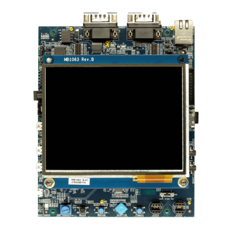
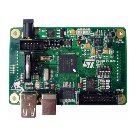
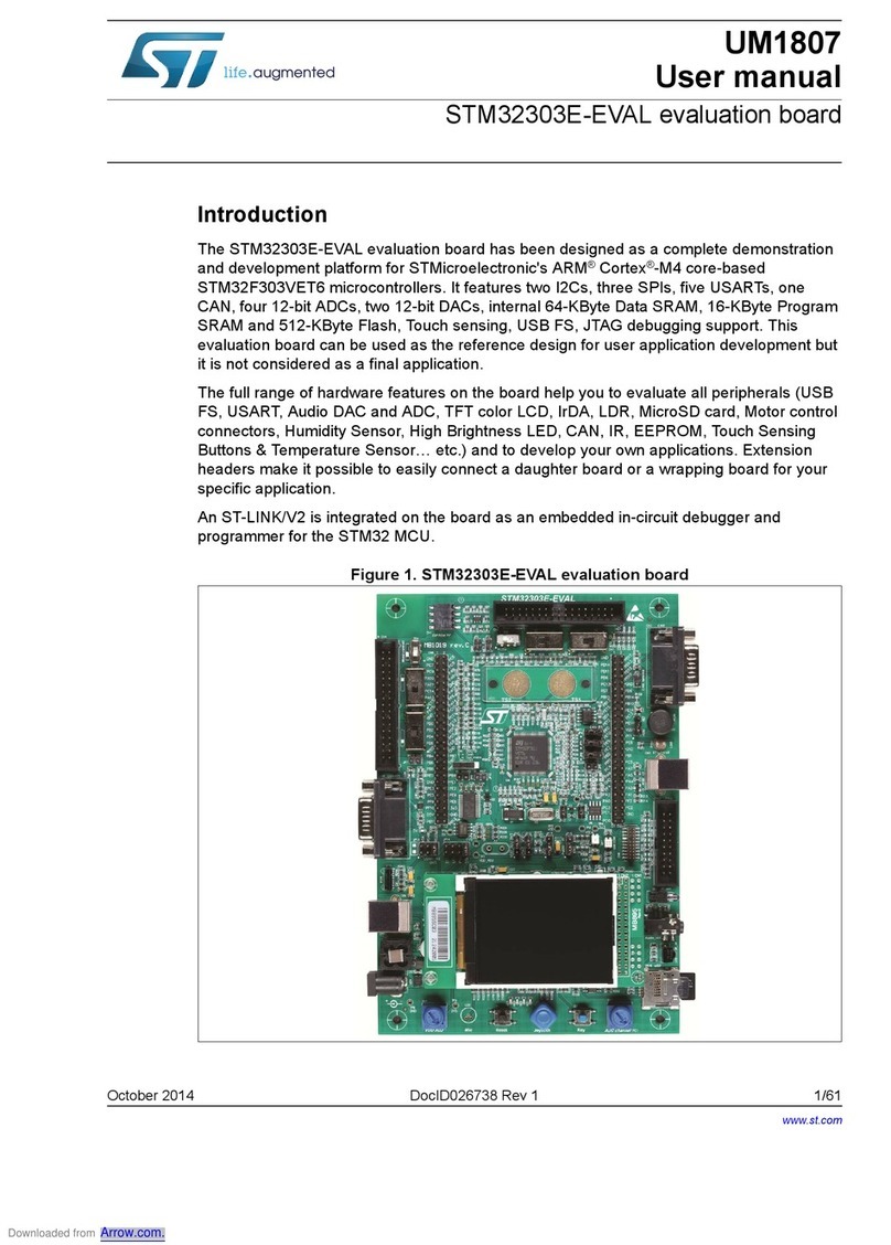
ST SPC564A-DISP Installation and operating instructions
Other ST Motherboard manuals
ST
ST M24SR-DISCOVERY User manual
ST
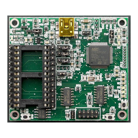
ST STM32F103RET6 User manual
ST
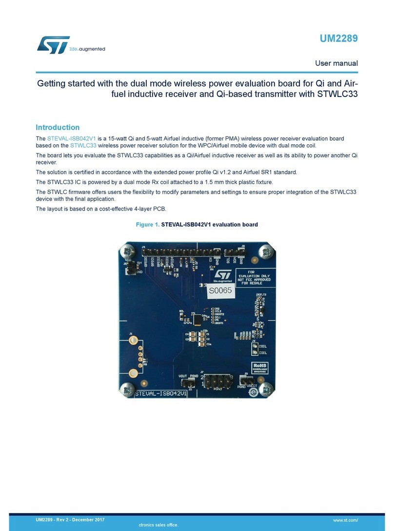
ST STEVAL-ISB042V1 User manual
ST
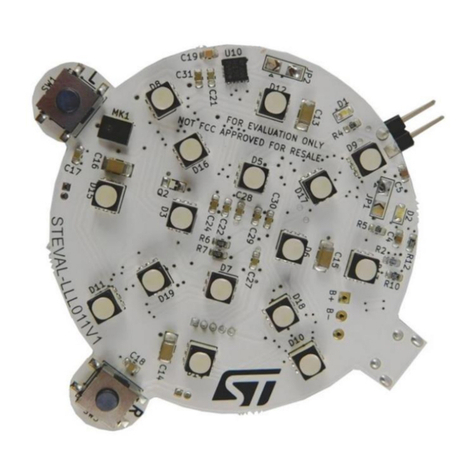
ST STEVAL-LLL011V1 User manual
ST
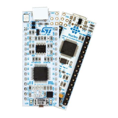
ST STM32 Nucleo-32 User manual
ST
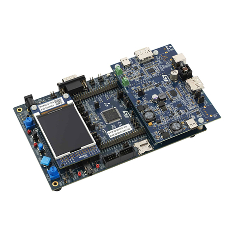
ST STM32G0C1E-EV User manual
ST
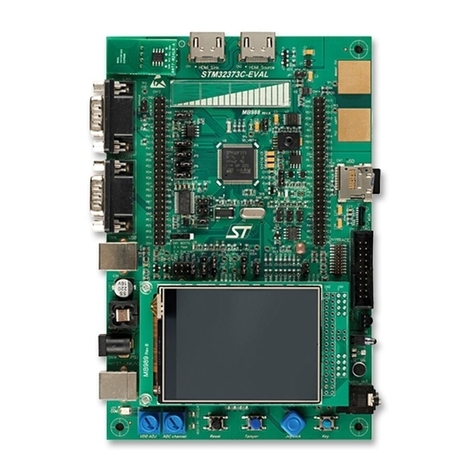
ST STM32373C-EVAL User manual
ST
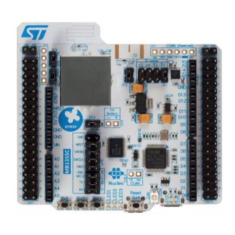
ST ST25DV-I2C User manual
ST
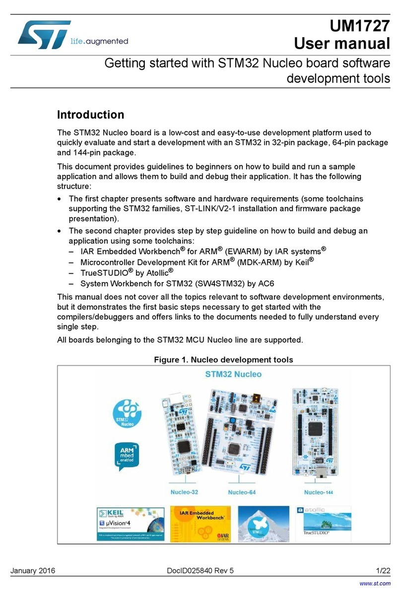
ST STM32 Nucleo User manual

ST
ST EVALSP820-XS User manual
ST
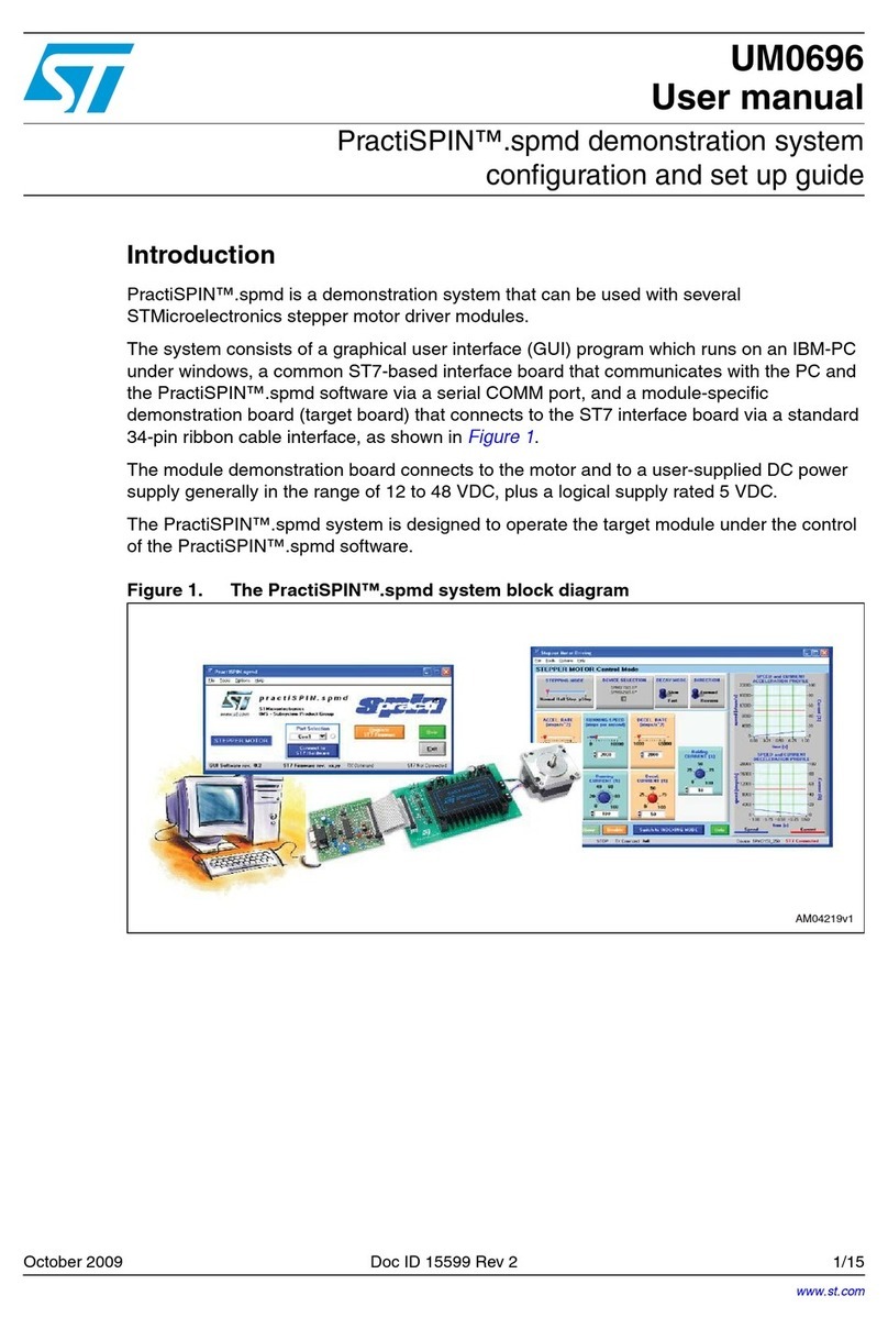
ST PractiSPIN UM0696 User manual
ST
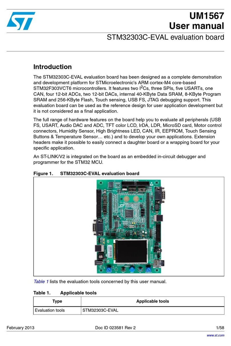
ST STM32303C-EVAL User manual
ST
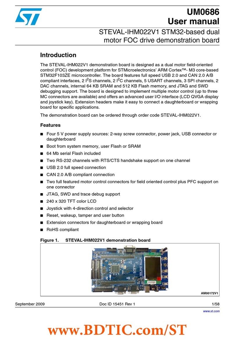
ST STEVAL-IHM022V1 User manual
ST
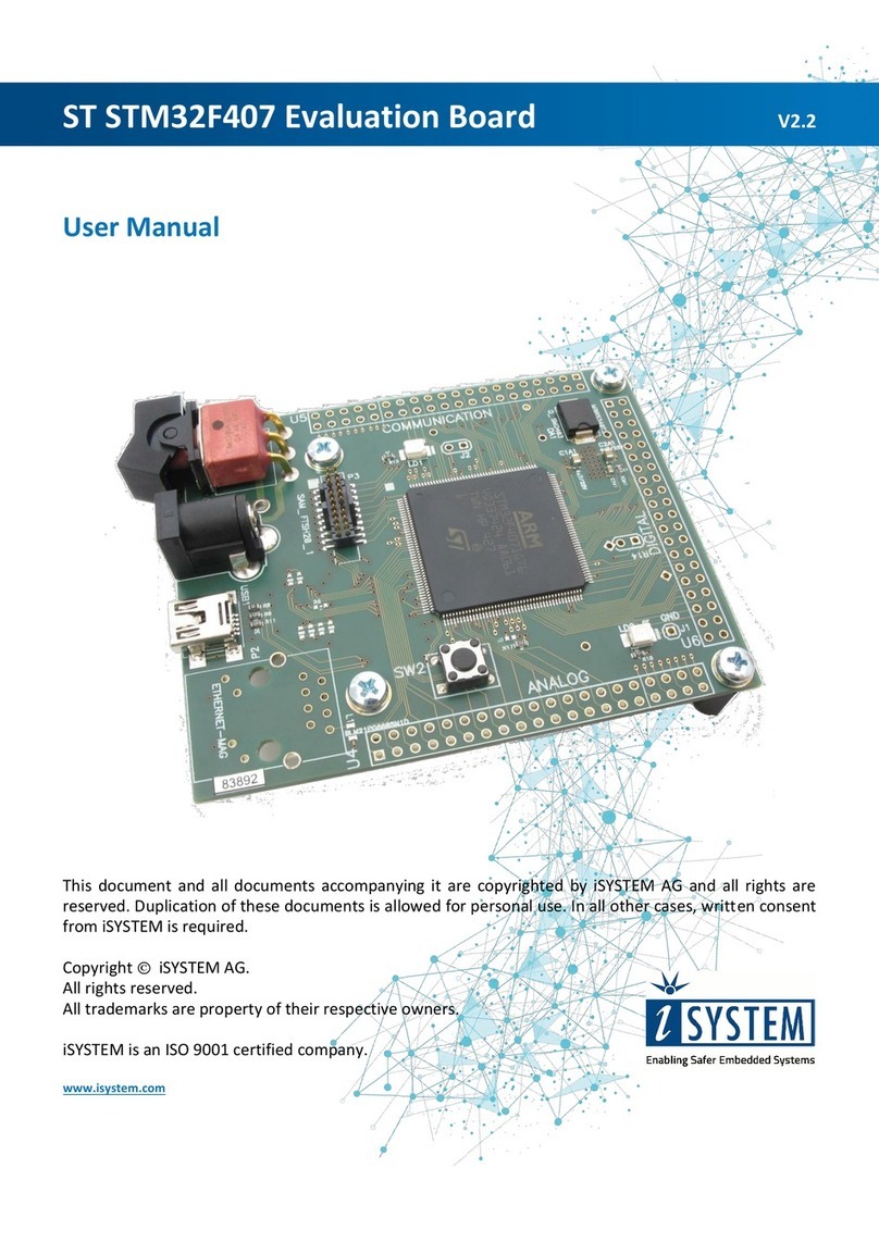
ST STM32F407 Series User manual
ST
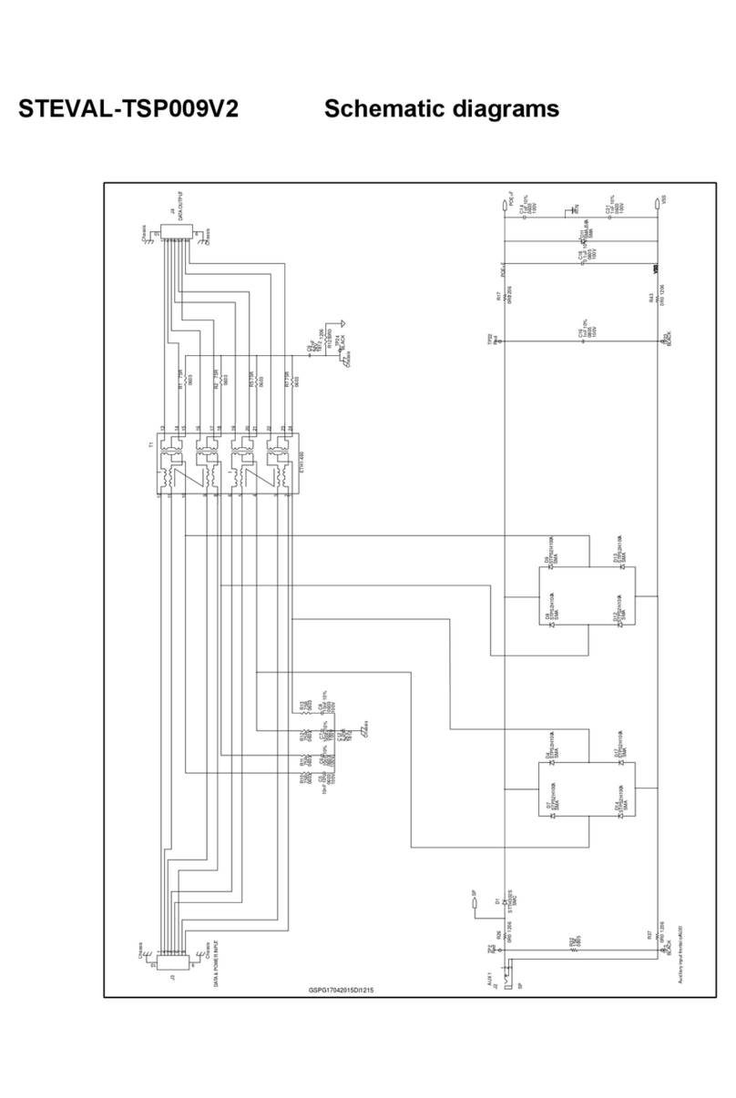
ST STEVAL-TSP009V2 Administrator Guide
ST
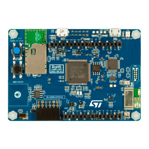
ST B-L4S5I-IOT01A User manual
ST
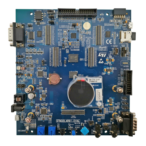
ST STM32L4R9I-EVAL User manual
ST
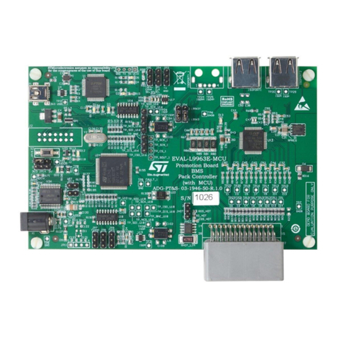
ST EVAL-L9963E-MCU User manual
ST
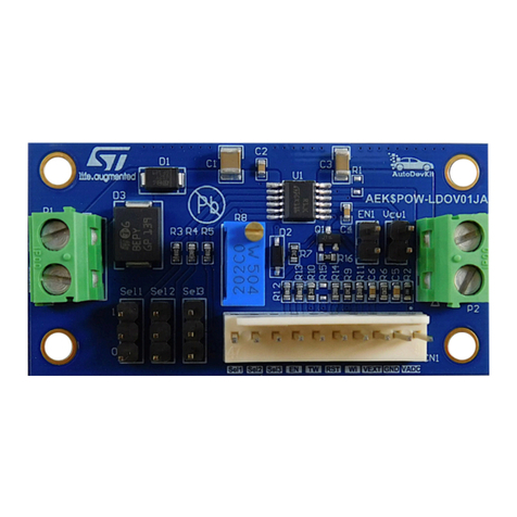
ST AEK-POW-LDOV01J User manual

ST
ST STM32L4R9I-EVAL User manual
