The STEVAL-IPE023V1 is not included in the package, therefore it should be ordered separately. Please read the
user manual, before using it.
2.3.1 Connection to PC GUI through the STEVAL-IPE023V1
To evaluate the board using the STEVAL-IPE023V1 and the STPM3x evaluation software:
1. Put J4 enable jumper in EN position
2. Put SW1 switches in OFF position, to "SPI" serigraphy
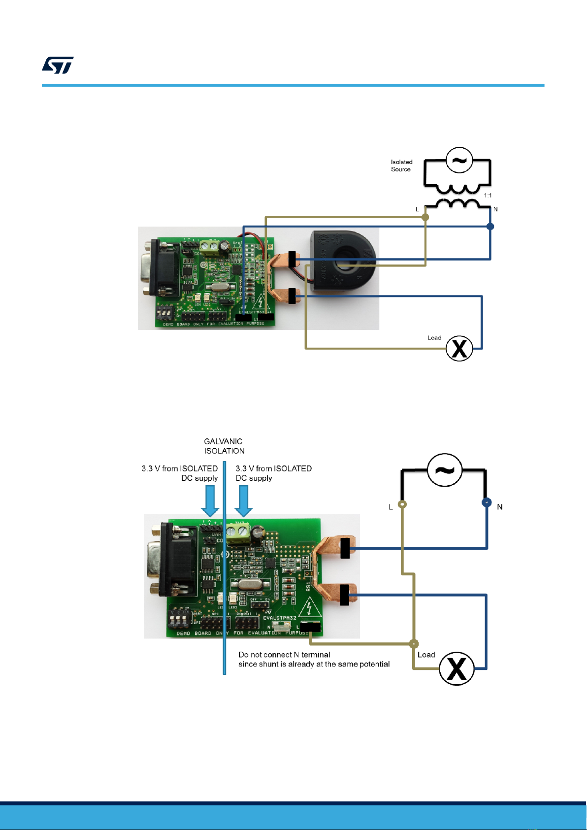
3. Connect J7 connector to 3.3 V DC isolated power supply, or put J4 jumper in the STEVAL-IPE023V1 board in
1-2 position (supply voltage set to 3.3 V)
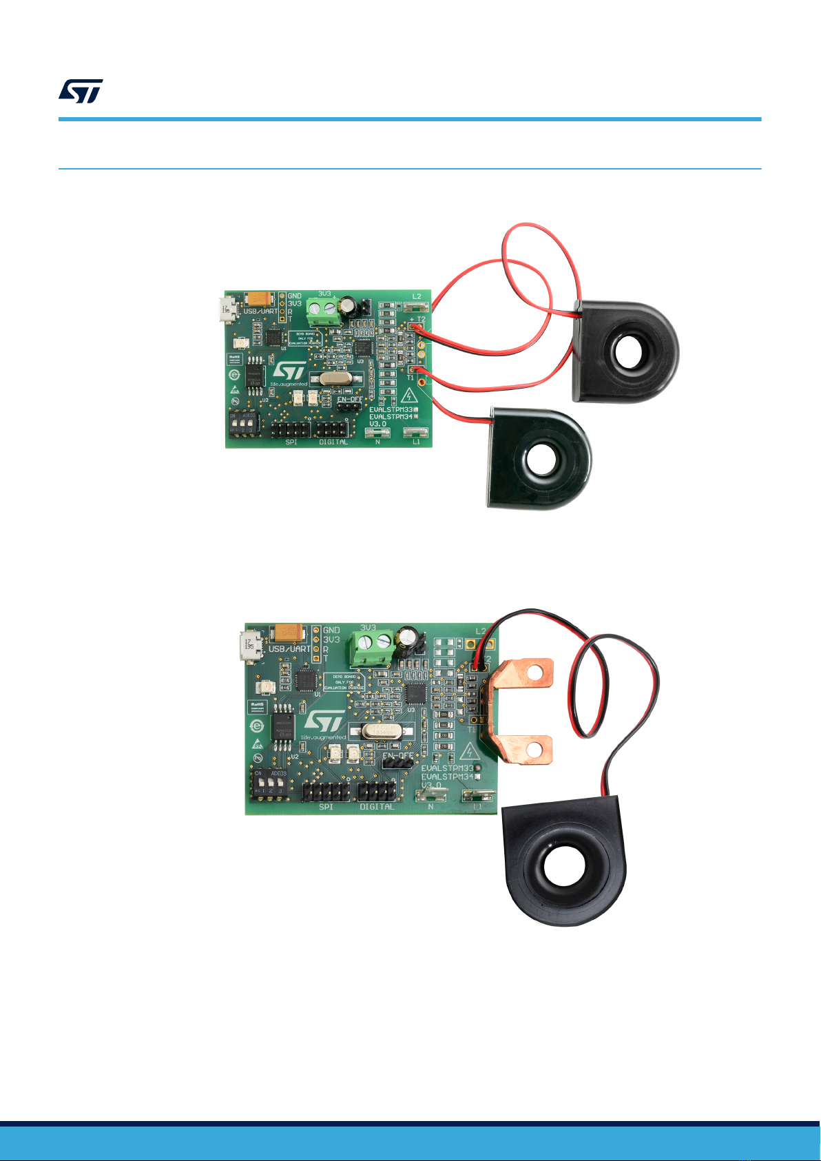
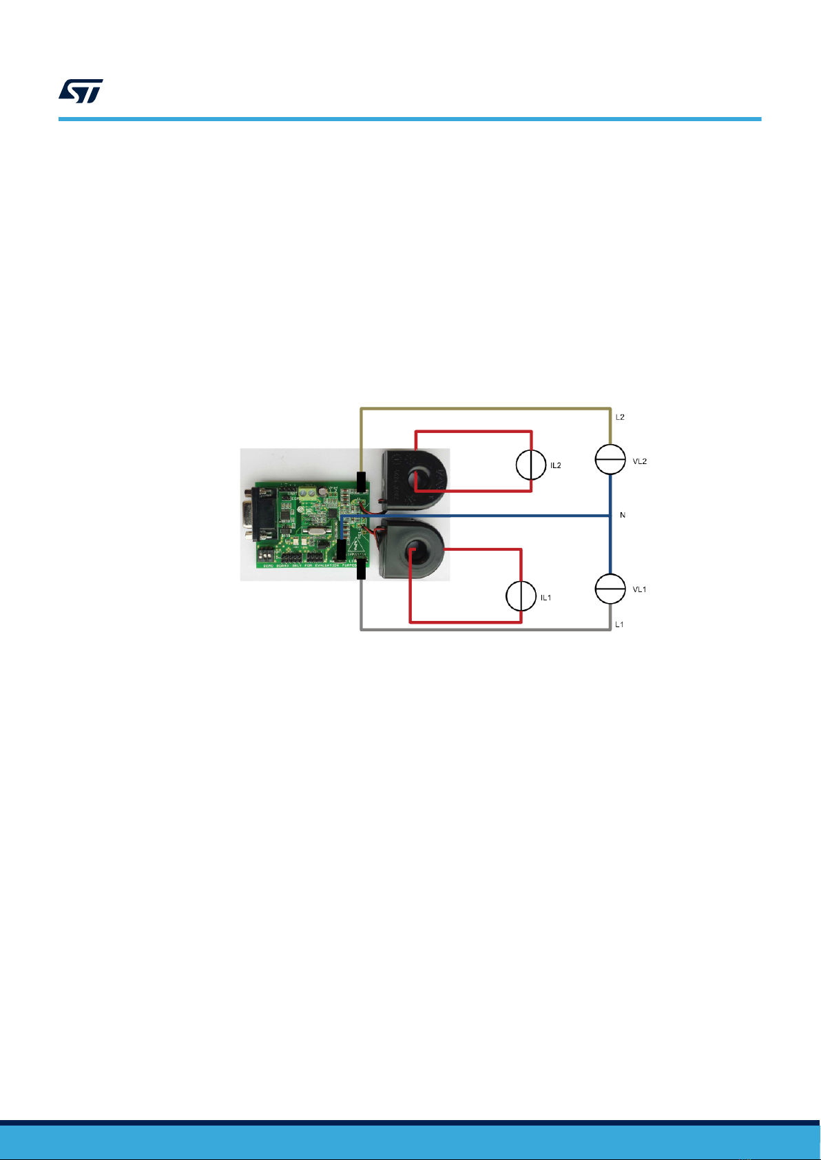
4. Connect the EVALSTPM3x board to either AC line or power source or phantom load as shown in
Section 2.2 Connection to the line, without powering it on
5. Connect the USB cable both to the STEVAL-IPE023V1 board and to PC
6. Connect the flat SPI cable from USB board to the EVALSTPM3x board
7. Power on AC source and DC source
8. Open GUI
9. When green LED on the STEVAL-IPE023V1 starts blinking, click "options", then "interface", select "STEVAL-
IPE023" and select the proper "serial port", baud rate is 19200
10. Now you can read, write, sample or calibrate the device
2.3.2 Connection to PC GUI through the on-board USB-to-UART port
To evaluate the board using a PC USB port and the STPM3x evaluation software:
1. Put J4 enable jumper in EN position
2. Put SW1 switches in ON position, to "UART" serigraphy
3. Connect J7 connector to 3.3 V DC power supply
4. Connect the EVALSTPM3x board to either AC line or power source or phantom load as shown in
Section 2.2 Connection to the line, without powering it on
5. Connect the USB cable both to the board and to PC
6. Power on AC source and DC source
7. Open GUI
8. Click "options", then "interface", select "USB" and select the proper "serial port", baud rate is 9600
9. Now you can read, write, sample or calibrate the device
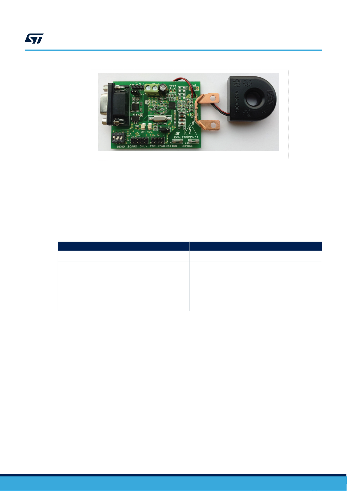
Connection to PC GUI through the RS232 port (board version 1 only):
To evaluate the board using a PC RS232 port and the STPM3x evaluation software:
1.Put J4 enable jumper in EN position
2.Put SW1 switches in ON position, to "UART" serigraphy
3.Connect J7 connector and J2 connectors to 3.3 V DC separated and isolated power supply
4.Enable RS232 port by inserting J3 jumper
5.Connect the EVALSTPM3x board to either AC line or power source or phantom load as shown in Section 2.1:
"Board description", without powering it on
6.Connect the serial cable both to the board and to PC
7.Power on AC source and DC source
8.Open GUI
9.Click "options", then "interface", select "UART" and select the proper "serial port", baud rate is 9600
10. Now you can read, write, sample or calibrate the device
2.4 The device basic configuration
During the startup, all internal device parameters are in the default value. For the EVALSTPM34 board, primary
channel gain GAIN[1:0] has to be changed to value 0 (current gain = x2), a correct energy measurement is, in
this manner, assured. All other parameters can be changed according to the needs (board calibration, phase-shift
compensation, desired output on the programmable pin,…). For further information on the device configuration,
please refer to the STPM3x datasheet.
UM1748
The device basic configuration
UM1748 - Rev 3 page 10/15