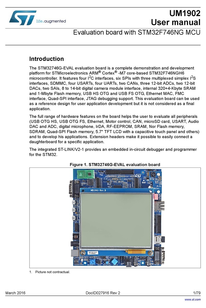
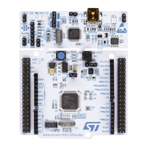
ST STM32L073Z-EVAL User manual

May 2018 UM1878 Rev 2 1/64
1
UM1878
User manual
Evaluation board with STM32L073VZ MCU
Introduction
The STM32L073Z-EVAL evaluation board is designed as a complete demonstration and
development platform for the STMicroelectronics Arm®Cortex®-M0+ core-based
STM32L073VZT6 microcontroller with three I2C buses, two SPI interfaces, four USART
interfaces, one UART interface, 12-bit ADC and DAC, LCD driver, up to 192-Kbyte Flash
memory, 20-Kbyte RAM, 6-Kbyte EEPROM, touch sensing, USB OTG FS, LCD controller,
SWD debugging support. This evaluation board can be used as reference design for user
application development but is not considered as a final application.
The full range of hardware features on the board help the user to evaluate all peripherals
(USB OTG FS, USART, 12-bit ADC and DAC, color TFT LCD, LCD glass, low-power UART,
IrDA, microSD™ card, touch sensing slider, pressure measurement, temperature
measurement, LC sensor metering) and develop his applications. The extension headers
offer the possibility to connect a daughterboard or a wrapping board for a specific
application.
An embedded ST-LINK/V2-1 debugger facilitates the software development and the
programming of the STM32L073VZT6 microcontroller.
Figure 1. STM32L073Z-EVAL evaluation board
Picture is not contractual.
www.st.com

Contents UM1878
2/64 UM1878 Rev 2
Contents
1 Features . . . . . . . . . . . . . . . . . . . . . . . . . . . . . . . . . . . . . . . . . . . . . . . . . . . 7
2 Product marking . . . . . . . . . . . . . . . . . . . . . . . . . . . . . . . . . . . . . . . . . . . . 8
3 System requirements . . . . . . . . . . . . . . . . . . . . . . . . . . . . . . . . . . . . . . . . 8
4 Development toolchains . . . . . . . . . . . . . . . . . . . . . . . . . . . . . . . . . . . . . . 8
5 Demonstration software . . . . . . . . . . . . . . . . . . . . . . . . . . . . . . . . . . . . . . 9
6 Ordering information . . . . . . . . . . . . . . . . . . . . . . . . . . . . . . . . . . . . . . . . 9
7 Hardware layout and configuration . . . . . . . . . . . . . . . . . . . . . . . . . . . . 10
7.1 Embedded ST-LINK/V2-1 . . . . . . . . . . . . . . . . . . . . . . . . . . . . . . . . . . . . .11
7.1.1 Drivers . . . . . . . . . . . . . . . . . . . . . . . . . . . . . . . . . . . . . . . . . . . . . . . . . . 12
7.1.2 ST-LINK/V2-1 firmware upgrade . . . . . . . . . . . . . . . . . . . . . . . . . . . . . . 12
7.2 SWD connectors . . . . . . . . . . . . . . . . . . . . . . . . . . . . . . . . . . . . . . . . . . . 13
7.3 Power supply . . . . . . . . . . . . . . . . . . . . . . . . . . . . . . . . . . . . . . . . . . . . . . 13
7.3.1 Adjustable power supply . . . . . . . . . . . . . . . . . . . . . . . . . . . . . . . . . . . . 16
7.4 Clock source . . . . . . . . . . . . . . . . . . . . . . . . . . . . . . . . . . . . . . . . . . . . . . . 17
7.5 Reset sources . . . . . . . . . . . . . . . . . . . . . . . . . . . . . . . . . . . . . . . . . . . . . 17
7.6 Boot option . . . . . . . . . . . . . . . . . . . . . . . . . . . . . . . . . . . . . . . . . . . . . . . . 18
7.7 USB FS . . . . . . . . . . . . . . . . . . . . . . . . . . . . . . . . . . . . . . . . . . . . . . . . . . 19
7.7.1 Operating voltage . . . . . . . . . . . . . . . . . . . . . . . . . . . . . . . . . . . . . . . . . 19
7.8 SMBus temperature sensor . . . . . . . . . . . . . . . . . . . . . . . . . . . . . . . . . . . 19
7.8.1 Limitations . . . . . . . . . . . . . . . . . . . . . . . . . . . . . . . . . . . . . . . . . . . . . . . 20
7.8.2 Operating voltage . . . . . . . . . . . . . . . . . . . . . . . . . . . . . . . . . . . . . . . . . 20
7.9 RS-232 USART2 and IrDA . . . . . . . . . . . . . . . . . . . . . . . . . . . . . . . . . . . . 20
7.9.1 RS-232 . . . . . . . . . . . . . . . . . . . . . . . . . . . . . . . . . . . . . . . . . . . . . . . . . . 20
7.9.2 IrDA . . . . . . . . . . . . . . . . . . . . . . . . . . . . . . . . . . . . . . . . . . . . . . . . . . . . 20
7.9.3 Limitations . . . . . . . . . . . . . . . . . . . . . . . . . . . . . . . . . . . . . . . . . . . . . . . 21
7.9.4 Operating voltage . . . . . . . . . . . . . . . . . . . . . . . . . . . . . . . . . . . . . . . . . 21
7.10 RS-232 LPUART . . . . . . . . . . . . . . . . . . . . . . . . . . . . . . . . . . . . . . . . . . . 21
7.10.1 Limitations . . . . . . . . . . . . . . . . . . . . . . . . . . . . . . . . . . . . . . . . . . . . . . . 21

UM1878 Rev 2 3/64
UM1878 Contents
4
7.10.2 Operating voltage . . . . . . . . . . . . . . . . . . . . . . . . . . . . . . . . . . . . . . . . . 21
7.11 Virtual Com Port . . . . . . . . . . . . . . . . . . . . . . . . . . . . . . . . . . . . . . . . . . . . 21
7.11.1 Limitations . . . . . . . . . . . . . . . . . . . . . . . . . . . . . . . . . . . . . . . . . . . . . . . 22
7.11.2 Operating voltage . . . . . . . . . . . . . . . . . . . . . . . . . . . . . . . . . . . . . . . . . 22
7.12 MicroSD card . . . . . . . . . . . . . . . . . . . . . . . . . . . . . . . . . . . . . . . . . . . . . . 22
7.12.1 Limitations . . . . . . . . . . . . . . . . . . . . . . . . . . . . . . . . . . . . . . . . . . . . . . . 22
7.12.2 Operating voltage . . . . . . . . . . . . . . . . . . . . . . . . . . . . . . . . . . . . . . . . . 22
7.13 Analog input ADC . . . . . . . . . . . . . . . . . . . . . . . . . . . . . . . . . . . . . . . . . . 22
7.13.1 Operating voltage . . . . . . . . . . . . . . . . . . . . . . . . . . . . . . . . . . . . . . . . . 24
7.14 Analog output DAC . . . . . . . . . . . . . . . . . . . . . . . . . . . . . . . . . . . . . . . . . 24
7.14.1 Limitations . . . . . . . . . . . . . . . . . . . . . . . . . . . . . . . . . . . . . . . . . . . . . . . 25
7.14.2 Operating voltage . . . . . . . . . . . . . . . . . . . . . . . . . . . . . . . . . . . . . . . . . 25
7.15 TFT LCD display . . . . . . . . . . . . . . . . . . . . . . . . . . . . . . . . . . . . . . . . . . . 26
7.15.1 Limitations . . . . . . . . . . . . . . . . . . . . . . . . . . . . . . . . . . . . . . . . . . . . . . . 26
7.15.2 Operating voltage . . . . . . . . . . . . . . . . . . . . . . . . . . . . . . . . . . . . . . . . . 26
7.16 User LEDs . . . . . . . . . . . . . . . . . . . . . . . . . . . . . . . . . . . . . . . . . . . . . . . . 26
7.17 Input devices . . . . . . . . . . . . . . . . . . . . . . . . . . . . . . . . . . . . . . . . . . . . . . 27
7.18 RF-EEPROM . . . . . . . . . . . . . . . . . . . . . . . . . . . . . . . . . . . . . . . . . . . . . . 27
7.19 LCD glass display module . . . . . . . . . . . . . . . . . . . . . . . . . . . . . . . . . . . . 27
7.19.1 Limitations . . . . . . . . . . . . . . . . . . . . . . . . . . . . . . . . . . . . . . . . . . . . . . . 31
7.20 LC sensor metering . . . . . . . . . . . . . . . . . . . . . . . . . . . . . . . . . . . . . . . . . 31
7.20.1 LC sensor metering principle . . . . . . . . . . . . . . . . . . . . . . . . . . . . . . . . . 32
7.20.2 LC sensor metering description . . . . . . . . . . . . . . . . . . . . . . . . . . . . . . . 33
7.20.3 Limitations . . . . . . . . . . . . . . . . . . . . . . . . . . . . . . . . . . . . . . . . . . . . . . . 35
7.21 Pressure sensor . . . . . . . . . . . . . . . . . . . . . . . . . . . . . . . . . . . . . . . . . . . . 35
7.21.1 Calculations . . . . . . . . . . . . . . . . . . . . . . . . . . . . . . . . . . . . . . . . . . . . . . 35
7.21.2 Errors . . . . . . . . . . . . . . . . . . . . . . . . . . . . . . . . . . . . . . . . . . . . . . . . . . . 37
7.21.3 Pressure computation . . . . . . . . . . . . . . . . . . . . . . . . . . . . . . . . . . . . . . 37
7.21.4 Filtering . . . . . . . . . . . . . . . . . . . . . . . . . . . . . . . . . . . . . . . . . . . . . . . . . 37
7.21.5 Limitations . . . . . . . . . . . . . . . . . . . . . . . . . . . . . . . . . . . . . . . . . . . . . . . 38
7.21.6 Operating voltage . . . . . . . . . . . . . . . . . . . . . . . . . . . . . . . . . . . . . . . . . 38
7.22 Touch sensing slider . . . . . . . . . . . . . . . . . . . . . . . . . . . . . . . . . . . . . . . . . 38
7.22.1 Limitations . . . . . . . . . . . . . . . . . . . . . . . . . . . . . . . . . . . . . . . . . . . . . . . 39
7.23 Extension connectors . . . . . . . . . . . . . . . . . . . . . . . . . . . . . . . . . . . . . . . . 39
7.24 IDD auto-measurement . . . . . . . . . . . . . . . . . . . . . . . . . . . . . . . . . . . . . . 40

Contents UM1878
4/64 UM1878 Rev 2
7.24.1 Analog section description . . . . . . . . . . . . . . . . . . . . . . . . . . . . . . . . . . . 41
7.24.2 Difference amplifier . . . . . . . . . . . . . . . . . . . . . . . . . . . . . . . . . . . . . . . . 42
7.24.3 Digital section description . . . . . . . . . . . . . . . . . . . . . . . . . . . . . . . . . . . 42
8 Connectors . . . . . . . . . . . . . . . . . . . . . . . . . . . . . . . . . . . . . . . . . . . . . . . 44
8.1 RS-232 connector CN6 . . . . . . . . . . . . . . . . . . . . . . . . . . . . . . . . . . . . . . 44
8.2 Power connector CN18 . . . . . . . . . . . . . . . . . . . . . . . . . . . . . . . . . . . . . . 44
8.3 LCD glass daughterboard connectors CN10 and CN14 . . . . . . . . . . . . . 45
8.4 ST-LINK/V2-1 programming connector CN15 . . . . . . . . . . . . . . . . . . . . . 46
8.5 ST-LINK/V2-1 USB Type B connector CN17 . . . . . . . . . . . . . . . . . . . . . . 46
8.6 SWD connector CN12 . . . . . . . . . . . . . . . . . . . . . . . . . . . . . . . . . . . . . . . 47
8.7 Trace debugging connector CN11 . . . . . . . . . . . . . . . . . . . . . . . . . . . . . . 47
8.8 MicroSD connector CN3 . . . . . . . . . . . . . . . . . . . . . . . . . . . . . . . . . . . . . . 48
8.9 RF-EEPROM daughterboard connector CN3 . . . . . . . . . . . . . . . . . . . . . 49
Appendix A Electrical schematics . . . . . . . . . . . . . . . . . . . . . . . . . . . . . . . . . . . . 50
Appendix B Mechanical dimensions. . . . . . . . . . . . . . . . . . . . . . . . . . . . . . . . . . . 62
Revision history . . . . . . . . . . . . . . . . . . . . . . . . . . . . . . . . . . . . . . . . . . . . . . . . . . . . 63

UM1878 Rev 2 5/64
UM1878 List of tables
5
List of tables
Table 1. Ordering information . . . . . . . . . . . . . . . . . . . . . . . . . . . . . . . . . . . . . . . . . . . . . . . . . . . . . . . 9
Table 2. Power related jumpers . . . . . . . . . . . . . . . . . . . . . . . . . . . . . . . . . . . . . . . . . . . . . . . . . . . . 14
Table 3. 32.768 KHz crystal X2 solder bridges. . . . . . . . . . . . . . . . . . . . . . . . . . . . . . . . . . . . . . . . . 17
Table 4. 8 MHz crystal X1 solder bridges . . . . . . . . . . . . . . . . . . . . . . . . . . . . . . . . . . . . . . . . . . . . . 17
Table 5. Boot related switch . . . . . . . . . . . . . . . . . . . . . . . . . . . . . . . . . . . . . . . . . . . . . . . . . . . . . . . 18
Table 6. Boot related jumper . . . . . . . . . . . . . . . . . . . . . . . . . . . . . . . . . . . . . . . . . . . . . . . . . . . . . . 19
Table 7. Temperature sensor related solder bridge . . . . . . . . . . . . . . . . . . . . . . . . . . . . . . . . . . . . . 20
Table 8. RS-232 and IrDA jumper settings . . . . . . . . . . . . . . . . . . . . . . . . . . . . . . . . . . . . . . . . . . . . 21
Table 9. MicroSD connector CN13 . . . . . . . . . . . . . . . . . . . . . . . . . . . . . . . . . . . . . . . . . . . . . . . . . . 22
Table 10. Analog input related jumper JP2 settings . . . . . . . . . . . . . . . . . . . . . . . . . . . . . . . . . . . . . . 25
Table 11. TFT LCD connector . . . . . . . . . . . . . . . . . . . . . . . . . . . . . . . . . . . . . . . . . . . . . . . . . . . . . . 26
Table 12. User LEDs . . . . . . . . . . . . . . . . . . . . . . . . . . . . . . . . . . . . . . . . . . . . . . . . . . . . . . . . . . . . . 26
Table 13. Input devices. . . . . . . . . . . . . . . . . . . . . . . . . . . . . . . . . . . . . . . . . . . . . . . . . . . . . . . . . . . . 27
Table 14. LCD glass segments 21 to 28 mapping table . . . . . . . . . . . . . . . . . . . . . . . . . . . . . . . . . . . 28
Table 15. LCD glass segments 0 and 29 to 39 mapping table . . . . . . . . . . . . . . . . . . . . . . . . . . . . . . 29
Table 16. LCD glass segments 1 to 8, 15, 18 to 20 mapping table . . . . . . . . . . . . . . . . . . . . . . . . . . 29
Table 17. LCD glass segments 9 to 14, 16, 17 mapping table . . . . . . . . . . . . . . . . . . . . . . . . . . . . . . 29
Table 18. LCD glass related jumpers and solder bridges. . . . . . . . . . . . . . . . . . . . . . . . . . . . . . . . . . 30
Table 19. Solder bridges and jumpers for LC sensor metering . . . . . . . . . . . . . . . . . . . . . . . . . . . . . 34
Table 20. Sensor differential voltage . . . . . . . . . . . . . . . . . . . . . . . . . . . . . . . . . . . . . . . . . . . . . . . . . 36
Table 21. Differential voltage . . . . . . . . . . . . . . . . . . . . . . . . . . . . . . . . . . . . . . . . . . . . . . . . . . . . . . . 37
Table 22. Single output voltage to the ADC . . . . . . . . . . . . . . . . . . . . . . . . . . . . . . . . . . . . . . . . . . . . 37
Table 23. Touch sensing related solder bridges. . . . . . . . . . . . . . . . . . . . . . . . . . . . . . . . . . . . . . . . . 38
Table 24. Extension connectors pin-out . . . . . . . . . . . . . . . . . . . . . . . . . . . . . . . . . . . . . . . . . . . . . . . 40
Table 25. IDD auto-measurement related jumper settings . . . . . . . . . . . . . . . . . . . . . . . . . . . . . . . . . 41
Table 26. RS-232 connector CN6. . . . . . . . . . . . . . . . . . . . . . . . . . . . . . . . . . . . . . . . . . . . . . . . . . . . 44
Table 27. LCD glass daughterboard connectors . . . . . . . . . . . . . . . . . . . . . . . . . . . . . . . . . . . . . . . . 45
Table 28. USB type B connector CN17 . . . . . . . . . . . . . . . . . . . . . . . . . . . . . . . . . . . . . . . . . . . . . . . 46
Table 29. SWD debugging connector CN12. . . . . . . . . . . . . . . . . . . . . . . . . . . . . . . . . . . . . . . . . . . . 47
Table 30. Trace debugging connector CN11 . . . . . . . . . . . . . . . . . . . . . . . . . . . . . . . . . . . . . . . . . . . 48
Table 31. MicroSD connector CN3 . . . . . . . . . . . . . . . . . . . . . . . . . . . . . . . . . . . . . . . . . . . . . . . . . . . 48
Table 32. RF-EEPROM daughterboard connector CN3 . . . . . . . . . . . . . . . . . . . . . . . . . . . . . . . . . . . 49
Table 33. Document revision history . . . . . . . . . . . . . . . . . . . . . . . . . . . . . . . . . . . . . . . . . . . . . . . . . 63

List of figures UM1878
6/64 UM1878 Rev 2
List of figures
Figure 1. STM32L073Z-EVAL evaluation board . . . . . . . . . . . . . . . . . . . . . . . . . . . . . . . . . . . . . . . . . 1
Figure 2. Hardware block diagram. . . . . . . . . . . . . . . . . . . . . . . . . . . . . . . . . . . . . . . . . . . . . . . . . . . 10
Figure 3. STM32L073Z-EVAL evaluation board (top view) . . . . . . . . . . . . . . . . . . . . . . . . . . . . . . . . 11
Figure 4. USB Composite device . . . . . . . . . . . . . . . . . . . . . . . . . . . . . . . . . . . . . . . . . . . . . . . . . . . . 12
Figure 5. Pin-out of 5 V DC adapter. . . . . . . . . . . . . . . . . . . . . . . . . . . . . . . . . . . . . . . . . . . . . . . . . . 14
Figure 6. Location of ADC input connector CN2 . . . . . . . . . . . . . . . . . . . . . . . . . . . . . . . . . . . . . . . . 23
Figure 7. Provision for filter implementation. . . . . . . . . . . . . . . . . . . . . . . . . . . . . . . . . . . . . . . . . . . . 23
Figure 8. Location of DAC output CN3 and JP2 . . . . . . . . . . . . . . . . . . . . . . . . . . . . . . . . . . . . . . . . 24
Figure 9. Provision for filter implementation. . . . . . . . . . . . . . . . . . . . . . . . . . . . . . . . . . . . . . . . . . . . 25
Figure 10. LCD glass board in LCD position . . . . . . . . . . . . . . . . . . . . . . . . . . . . . . . . . . . . . . . . . . . . 28
Figure 11. LCD glass board in IO position . . . . . . . . . . . . . . . . . . . . . . . . . . . . . . . . . . . . . . . . . . . . . . 28
Figure 12. LCD segment names . . . . . . . . . . . . . . . . . . . . . . . . . . . . . . . . . . . . . . . . . . . . . . . . . . . . . 30
Figure 13. Functional block diagram of LC sensor metering . . . . . . . . . . . . . . . . . . . . . . . . . . . . . . . . 32
Figure 14. LC sensor metering schematic . . . . . . . . . . . . . . . . . . . . . . . . . . . . . . . . . . . . . . . . . . . . . . 33
Figure 15. Differential amplifier with offset correction . . . . . . . . . . . . . . . . . . . . . . . . . . . . . . . . . . . . . 36
Figure 16. Solder bridges settings to enable the touch slider (red = closed, green = opened) . . . . . . 39
Figure 17. Figure: analog section schematic . . . . . . . . . . . . . . . . . . . . . . . . . . . . . . . . . . . . . . . . . . . . 41
Figure 18. Difference amplifier. . . . . . . . . . . . . . . . . . . . . . . . . . . . . . . . . . . . . . . . . . . . . . . . . . . . . . . 42
Figure 19. Digital section schematic . . . . . . . . . . . . . . . . . . . . . . . . . . . . . . . . . . . . . . . . . . . . . . . . . . 43
Figure 20. RS-232 connector CN6 (front view) . . . . . . . . . . . . . . . . . . . . . . . . . . . . . . . . . . . . . . . . . . 44
Figure 21. Power supply connector CN18 . . . . . . . . . . . . . . . . . . . . . . . . . . . . . . . . . . . . . . . . . . . . . . 44
Figure 22. USB type B connector CN17 . . . . . . . . . . . . . . . . . . . . . . . . . . . . . . . . . . . . . . . . . . . . . . . 46
Figure 23. Trace debugging connector CN12 (top view) . . . . . . . . . . . . . . . . . . . . . . . . . . . . . . . . . . . 47
Figure 24. Trace debugging connector CN11 (top view) . . . . . . . . . . . . . . . . . . . . . . . . . . . . . . . . . . . 47
Figure 25. MicroSD connector CN3 . . . . . . . . . . . . . . . . . . . . . . . . . . . . . . . . . . . . . . . . . . . . . . . . . . . 48
Figure 26. RF-EEPROM daughterboard connector CN3 (front view) . . . . . . . . . . . . . . . . . . . . . . . . . 49
Figure 27. STM32L073Z-EVAL . . . . . . . . . . . . . . . . . . . . . . . . . . . . . . . . . . . . . . . . . . . . . . . . . . . . . . 50
Figure 28. MCU . . . . . . . . . . . . . . . . . . . . . . . . . . . . . . . . . . . . . . . . . . . . . . . . . . . . . . . . . . . . . . . . . . 51
Figure 29. LCD glass external connector. . . . . . . . . . . . . . . . . . . . . . . . . . . . . . . . . . . . . . . . . . . . . . . 52
Figure 30. Power . . . . . . . . . . . . . . . . . . . . . . . . . . . . . . . . . . . . . . . . . . . . . . . . . . . . . . . . . . . . . . . . . 53
Figure 31. Peripherals . . . . . . . . . . . . . . . . . . . . . . . . . . . . . . . . . . . . . . . . . . . . . . . . . . . . . . . . . . . . . 54
Figure 32. TFT microSD . . . . . . . . . . . . . . . . . . . . . . . . . . . . . . . . . . . . . . . . . . . . . . . . . . . . . . . . . . . 55
Figure 33. USART_LPUART . . . . . . . . . . . . . . . . . . . . . . . . . . . . . . . . . . . . . . . . . . . . . . . . . . . . . . . . 56
Figure 34. Pressure sensor . . . . . . . . . . . . . . . . . . . . . . . . . . . . . . . . . . . . . . . . . . . . . . . . . . . . . . . . . 57
Figure 35. LC sensor metering . . . . . . . . . . . . . . . . . . . . . . . . . . . . . . . . . . . . . . . . . . . . . . . . . . . . . . 58
Figure 36. IDD measurement. . . . . . . . . . . . . . . . . . . . . . . . . . . . . . . . . . . . . . . . . . . . . . . . . . . . . . . . 59
Figure 37. SWD, Touch, USB . . . . . . . . . . . . . . . . . . . . . . . . . . . . . . . . . . . . . . . . . . . . . . . . . . . . . . . 60
Figure 38. ST-LINK/V2-1 . . . . . . . . . . . . . . . . . . . . . . . . . . . . . . . . . . . . . . . . . . . . . . . . . . . . . . . . . . . 61
Figure 39. Mechanical dimensions . . . . . . . . . . . . . . . . . . . . . . . . . . . . . . . . . . . . . . . . . . . . . . . . . . . 62
UM1878 Rev 2 7/64
UM1878 Features
63
1 Features
•STM32L073VZT6 ultra-low-power Arm®(a) Cortex®core-based microcontroller
featuring 192 Kbytes of Flash memory and 20 Kbytes of RAM in LQFP100 package
•Four 5 V power supply options: power jack, ST-LINK USB connector, user USB FS
connector, or daughterboard
•Selectable MCU voltage: 3.3 V or adjustable from 1.7 V to 3.6 V
•2.8-inch color TFT LCD with resistive touchscreen
•LCD glass 40 x 8 segments
•On-board current measurement
•IrDA transceiver
•Pressure sensor
•LC sensor metering
•Touch-sensing linear sensor
•User and reset push-buttons
•4-direction joystick with selection button
•Board connectors:
– 2 RS-232 with DB9
– USB with Micro-B
– microSD™ card interface
•Board expansion connectors:
– RF-EEPROM daughterboard
– Extension connector for daughterboard or wrapping board
•On-board ST-LINK/V2-1 debugger/programmer with USB re-enumeration capability:
mass storage, virtual COM port and debug port
•Comprehensive free software libraries and examples available with the STM32Cube
package
•Support of a wide choice of integrated development environments (IDEs), including
IAR™, Keil®and GCC-based IDEs
a. Arm is a registered trademark of Arm Limited (or its subsidiaries) in the US and/or elsewhere.

Product marking UM1878
8/64 UM1878 Rev 2
2 Product marking
Evaluation tools marked as “ES” or “E” are not yet qualified and are therefore not ready to
be used as reference design or in production. Any consequences arising from such usage
will not be at STMicroelectronics’ charge. In no event will STMicroelectronics be liable for
any customer usage of these engineering sample tools as reference designs or in
production.
‘E’ or ‘ES’ marking examples of location:
•on the targeted STM32 that is soldered on the board (for illustration of STM32 marking,
refer to the section Package information in the STM32 datasheet at www.st.com).
•next to the evaluation tool ordering part number, that is stuck or silkscreen printed on
the board
This board features a specific STM32 device version, which allows the operation of any
bundled commercial stack/library available. This STM32 device shows a "U" marking option
at the end of the standard part number and is not available for sales.
In order to use the same commercial stack in his application, a developer may need to
purchase a part number specific to this stack/library. The price of those part numbers
includes the stack/library royalties.
3 System requirements
•Windows®OS (7, 8 and 10), Linux®64-bit or macOS®(a)
•USB Type-A to Micro-B cable
4 Development toolchains
•Keil®MDK-ARM(b)
•IAR™ EWARM(b)
•GCC-based IDEs including free SW4STM32 from AC6
a. macOS® is a trademark of Apple Inc., registered in the U.S. and other countries.
b. On Windows only

UM1878 Rev 2 9/64
UM1878 Demonstration software
63
5 Demonstration software
The demonstration software, included in the STM32Cube MCU Package corresponding to
the on-board MCU, is preloaded in the STM32 Flash memory for easy demonstration of the
device peripherals in standalone mode. The latest versions of the demonstration source
code and associated documentation can be downloaded from www.st.com.
6 Ordering information
To order the STM32L073Z-EVAL Evaluation board, refer to Table 1.
Table 1. Ordering information
Order code Target STM32
STM32L073Z-EVAL STM32L073VZT6

Hardware layout and configuration UM1878
10/64 UM1878 Rev 2
7 Hardware layout and configuration
STM32L073Z-EVAL evaluation board is designed around the STM32L073VZT6 (LQFP 100
package). The hardware block Figure 2: Hardware block diagram illustrates the connections
between the STM32L073VZT6 and peripherals while Figure 3: STM32L073Z-EVAL
evaluation board (top view) helps the user to locate these features on the actual evaluation
board.
Figure 2. Hardware block diagram
06Y9
*3,2
,&
86$57
6:'
-R\VWLFN
[/('V
:DNH8S7DPSHU
EXWWRQ%
(PEHGGHG
67/,1.9
6:'FRQQHFWRUV
670/=
&RPSDUDWRU
63,
*3,2
86% 86%0LFUR%
FRQQHFWRU
FRORU
/&'
7HPSHUDWXUHVHQVRU
$'&
/&'*ODVV
[
/38$57
76&7RXFK VHQVLQJVOLGHU
9UHJXODWRU
'$&
$'&LQSXW
60%
$'&ELWV
86$57
*3,2
/37LPHU
/&VHQVRU
'$&
RXWSXW
9LUWXDO
&RP3RUW
86%
7\SH%
FRQQHFWRU
0LFUR6'
FDUG
¶¶
/&'7)7
3UHVVXUH
VHQVRU
56
&RQQHFWRU
56
&RQQHFWRU
56
WUDQVFHLYHU
,U'$
WUDQVFHLYHU
56
WUDQVFHLYHU
'LIIHUHQWLDO
DPSOLILHU
5)((3520
FRQQHFWRU
([WHQVLRQ
&RQQHFWRU
,2
([SDQGRU
9''B86%
9
UHJXODWRU
WR9
DGMXVWDEOH
UHJXODWRU
0&8
FRQVXPSWLRQ
DXWRPHDVXUHPHQW
([WHQVLRQ
FRQQHFWRUVIRU
*3,2V

UM1878 Rev 2 11/64
UM1878 Hardware layout and configuration
63
Figure 3. STM32L073Z-EVAL evaluation board (top view)
7.1 Embedded ST-LINK/V2-1
The ST-LINK/V2-1 programming and debugging tool is integrated on the
STM32L073Z-EVAL evaluation board. Compared to ST-LINK/V2 the changes are listed
below.
06Y9
/&VHQVRU
&1DQG&1
([WHQVLRQ
FRQQHFWRUV
&1
8
SUHVVXUH
VHQVRU
/6
7RXFK
VOLGHU
&1
5)((3520
8
,U'$
&1
/38$57
&1DQG
&1
/&'JODVV
FRQQHFWRUV
&1
6:'
&1
6:'
%
MR\VWLFN
%
7DPSHUNH\
EXWWRQ
%
UHVHW
EXWWRQ
59
9''
DGMXVWPHQW
9ROWDJH
UDQJH
/('V
&1
3RZHUMDFN
&1
PLFUR6'
FDUG
8
670/=*
&1
86$57
&1
86%27*)6
&1
/&'7)7
-3
9VRXUFH
VHOHFWLRQ
6:
%RRWPRGH
67/,1.9
FRORU
/('V

Hardware layout and configuration UM1878
12/64 UM1878 Rev 2
The new features supported on ST-LINK/V2-1 are:
•USB software re-enumeration
•Virtual com port interface on USB
•Mass storage interface on USB
•USB power management request for more than 100 mA power on USB
This feature is no more supported on ST-LINK/V2-1:
•SWIM interface
For all general information concerning debugging and programming features common
between V2 and V2-1 refer to ST-LINK/V2 User Manual UM1075.
Known limitation:
Activating the readout protection on ST-LINK/V2-1 target, prevents the target application
from running afterwards. The target readout protection must be kept disabled on ST-
LINK/V2-1 boards.
Note: It is possible to power the board via CN17 (Embedded ST-LINK/V2-1 USB connector) even
if an external tool is connected to connectors CN11 or CN12.
7.1.1 Drivers
The ST-LINK/V2-1 requires a dedicated USB driver, which can be found on www.st.com for
Windows®XP, 7, 8.
In case the STM32L073Z-EVAL evaluation board is connected to the PC before the driver is
installed, some STM32L073Z-EVAL interfaces may be declared as “Unknown” in the PC
device manager. In this case the user must install the driver files, and update the driver of
the connected device from the device manager.
Note: Prefer using the “USB Composite Device” handle for a full recovery.
Figure 4. USB Composite device
7.1.2 ST-LINK/V2-1 firmware upgrade
The ST-LINK/V2-1 embeds a firmware upgrade mechanism for in-situ upgrade through the
USB port. As the firmware may evolve during the life time of the ST-LINK/V2-1 product (for
example new functionality, bug fixes, support for new microcontroller families), it is

UM1878 Rev 2 13/64
UM1878 Hardware layout and configuration
63
recommended to visit www.st.com before starting to use the STM32L073Z-EVAL evaluation
board and periodically, in order to stay up-to-date with the latest firmware version.
7.2 SWD connectors
Only Serial Wire Debug interface can be used on trace connectors CN11 and CN12.
SWDIO, SWCLK and RESET of the microcontroller STM32L073VZT6 are available. The
parallel trace and JTAG are not available on the STM32L073VZT6 microcontroller.
7.3 Power supply
STM32L073Z-EVAL evaluation board is designed to be powered by a 5 V DC power supply
and to be protected from wrong power plug-in event by PolyZen. It is possible to configure
the evaluation board to use any of the following four power supply sources:
•a 5 V DC power adapter connected on the board to the power jack CN18, called
PSU_E5V on silkscreen. It is selected by a jumper placed in E5V location of JP11. The
external power supply does not come with the board but can be ordered separately.
•a 5 V DC power with 300 mA limitation from the USB type B connector of
ST-LINK/V2-1 CN17 (silkscreen marking (ST-LINK/V2)).Note that only the ST-LINK
part is power supplied before the USB enumeration, as the host PC only provides 100
mA to the board at that time. During the USB enumeration, the STM32L073Z-EVAL
evaluation board requires 300 mA of current to the host PC. If the host is able to
provide the required power, the enumeration ends by a “SetConfiguration” command
and then, the power switch ST890 U29 is switched ON, the red LED LD5 is turned ON,
thus the evaluation board can consume a maximum of 300 mA current, not more. If the
host is not able to provide the required current, the enumeration fails, therefore the
power switch U29 remains OFF and the STM32 including its peripherals will not be
powered. As a consequence the red LED LD5 remains turned OFF. In such case it is
mandatory to use one external power supply connected to power jack CN18. This
power switch features also a current limitation to protect the PC in case of short-circuit
on board. If overcurrent (more than 600 mA) happens on board, the LED LD10 is
lighted on.
•5 V DC power with 500 mA limitation from the USB FS connector CN9. This connector
is a micro B receptacle with a silkscreen marking on the PCB: USB. This 5 V input is
called U5V.
•5 V DC power from a customer daughterboard plugged in pin 24 of extension
connector CN4. This 5 V input is called D5V.
Note: The 5 V DC power adapter should have the positive polarity at center pin, as shown in
Figure 5: Pin-out of 5 V DC adapter.

Hardware layout and configuration UM1878
14/64 UM1878 Rev 2
Figure 5. Pin-out of 5 V DC adapter
The power supply selection is done by the jumpers JP11, JP12, JP7, JP4, JP5 and JP13
as described in Table 2: Power related jumpers.
Table 2. Power related jumpers
Jumper Description
JP11
JP11 is used to select one of the four possible power supply sources.
To supply STM32L073Z-EVAL only from a 5 V power adapter connected to CN18
(PSU_E5V), set the jumper to E5V location, as following (Default setting):
To supply STM32L073Z-EVAL only from the USB connector CN9 set the jumper to
U5V location, as following:
To supply STM32L073Z-EVAL only from the USB connector CN17 of ST-LINK/V2,
set the jumper JP11 to STlk location, as showed in the below figure. In this case, the
jumper of ST-LINK JP13 should be opened.
06Y9
hϱs
^d><
ϱs
ϱs
06Y9
hϱs
^d><
ϱs
ϱs
06Y9
hϱs
^d><
ϱs
ϱs

UM1878 Rev 2 15/64
UM1878 Hardware layout and configuration
63
JP11
To supply both STM32L073Z-EVAL and a daughterboard connected to extension
connectors CN4 and CN5, (daughterboard should have its own power supply
not connected), set jumpers to E5V and D5V locations, as following:
JP12
VDD_MCU (pins VDD of STM32L073Z) is connected to fixed +3.3 V DC power when
JP12 is set as shown (Default setting):
VDD_MCU is connected to the adjustable DC power from 1.65 V to 3.6 V when JP12
is set as shown:
JP7
VDD_MCU power pin of STM32L073Z is connected to VDD_MCU when JP7 is set as
shown (Default setting):
VDD_MCU power pin of STM32L073Z is powered by the USB connector CN9 when
JP7 is set as shown here:
Table 2. Power related jumpers (continued)
Jumper Description
06Y9
hϱs
^d><
ϱs
ϱs
06Y9
06Y9
06Y9
06Y9

Hardware layout and configuration UM1878
16/64 UM1878 Rev 2
The red LED LD5 is on when the board STM32L073Z-EVAL is powered correctly by the 5 V.
7.3.1 Adjustable power supply
As detailed above the STM32L073VZT6 microcontroller can be supplied by a variable
voltage when pins 2 and 3 of JP12 are connected by a jumper. Use the potentiometer RV1
JP7
VDD_MCU power pin of STM32L073Z can be powered externally by an external
power supply, providing no jumper is connected to JP7. The external supply can be
connected to pin2 of JP7, as shown here:
JP4
VDDA power pin of STM32L073Z is connected to VDD_MCU when JP4 is closed as
shown (default setting):
To measure the current drawn by VDDA pin of STM32L073Z, remove the jumper of
JP4 and connect an ampere-meter to JP4, positive terminal to pin 1, negative to pin
2.
JP5
VREF+ pin of STM32L073Z is connected to VDD_MCU when JP5 is closed as shown
(default setting):
To measure the current drawn by VREF+ pin of STM32L073Z, remove the jumper of
JP5 and connect an ampere-meter to JP5, positive terminal to pin 1, negative to pin
2.
JP13
By default JP13 is not connected to let ST-LINK detect automatically if it should
provide the supply of the board from ST-LINK USB VBUS (default setting).
If JP13 is connected, ST-LINK will never supply the evaluation board from ST-LINK
USB.
Table 2. Power related jumpers (continued)
Jumper Description
06Y9
([WHUQDOSRZHU
VXSSO\
06Y9
06Y9
06Y9
06Y9

UM1878 Rev 2 17/64
UM1878 Hardware layout and configuration
63
to adjust the voltage from 1.65 V to 3.6 V. The three LEDs LD7, LD8, LD9 warn the user that
voltage is below 1.7 V or above 1.8 V.
7.4 Clock source
Two clock sources are available for the microcontroller STM32L073VZT6 on the evaluation
board STM32L073Z-EVAL:
•The 32.768 KHz crystal X2 for embedded RTC
•The 8 MHz crystal X1 8 MHz with a socket. It can be removed when the internal RC
clock is used.
7.5 Reset sources
The RESET signal of STM32L073Z-EVAL evaluation board is active low.
Table 3. 32.768 KHz crystal X2 solder bridges
Solder bridge Description
SB27
Open (default setting) PC14 is connected to the crystal X2.
closed
PC14 is connected to pin11 of extension connector CN5. In such
case R49 must be removed to avoid disturbance due to the 32Khz
quartz X2.
SB26
Open (default setting) PC15 is connected to 32 KHz crystal.
closed
PC15 is connected to pin 12 of extension connector CN5. In such
case R48 must be removed to avoid disturbance due to the 32Khz
quartz X2.
Table 4. 8 MHz crystal X1 solder bridges
Solder bridge Description
SB25
Open (default setting) PH0 is connected to 8 MHz crystal X1.
closed
PH0 is connected to pin 8 of extension connector CN5. In such
case X1 and C27 must be removed to avoid disturbance due to the
crystal.
SB23
Open (default setting) PH1 is connected to 8 MHz crystal X1.
closed
PH1 is connected to pin 7 of extension connector CN5. In such
case R342 must be removed to avoid disturbance due to the
crystal.

Hardware layout and configuration UM1878
18/64 UM1878 Rev 2
Sources of reset are:
•Reset button B1
•Debugging tools from SWD connectors CN12 and CN11.
•From a daughterboard connected to extension connectors, RESET is pin 24 of
connector CN5.
•Embedded ST-LINK/V2-1
•RS-232 connector CN6 for ISP. Jumper JP6 should be closed for RESET to be handled
by pin 8 of RS-232 connector CN6 (CTS signal).
7.6 Boot option
After reset, the STM32L073VZT6 MCU can boot from the following embedded memory
locations:
•User Flash memory
•System Flash memory
•Embedded RAM (for debugging)
The microcontroller is configured to one of the listed boot options by setting the
STM32L073VZT6 port BOOT0 level by the switch SW1 and by setting nBOOT1 bit of
FLASH_OPTR option bytes register, as shown in Tabl e 5. Depending on JP3, BOOT0 level
can be forced to high and, SW1 action overruled, by DSR line of RS-232 connector CN6, as
shown in Table 6: Boot related jumper. This can be used to force the execution of the
bootloader and start user Flash memory flashing process (ISP) from RS-232 interface. The
option bytes of STM32L073VZT6 and their modification procedure are described in the
reference manual RM0367. STM32 microcontroller system memory boot mode Application
Note (AN2606) details the bootloader mechanism and configurations.
Table 5. Boot related switch
Switch Description
SW1
(default setting)
STM32L073Z-EVAL evaluation board boots from User Flash. BOOT0 pin
is tied to “Low”.
STM32L073VZT6 boots from system Flash memory (nBOOT1 bit of
FLASH_OPTR register is set high) or from RAM (nBOOT1 is set low).
BOOT0 pin is tied to "high".

UM1878 Rev 2 19/64
UM1878 Hardware layout and configuration
63
7.7 USB FS
STM32L073Z-EVAL evaluation board supports USB2.0 FS communication. The USB
connector is the micro-B type connector CN9.
The USB functionality is independent of LCD glass connectors.
STM32L073VZT6 ports PA11 and PA12 are used for the USB DM and DP signals
respectively. In case PA11 and PA12 are not used for USB, it can be accessed for another
usage by the extension connector CN4, providing resistors R69 and R70 are removed.
USB section of the micro-controller STM32L073VZT6 VDD_USB must be supplied with 3.0 to
3.6 V internally or externally through jumper JP7. Refer to Section 7.3: Power supply for
more details regarding JP7 use.
7.7.1 Operating voltage
•If VDD_USB is supplied from VDD: USB is working typically with VDD > 3.0 V. JP7 pins 1
and 2 should be connected, please refer to Section 7.3: Power supply for more details.
•If VDD_USB is supplied from USB (U5V voltage), STM32L073Z-EVAL is functional in all
the voltage range: 1.65 V to 3.6 V.
7.8 SMBus temperature sensor
A temperature sensor STLM75M2F is connected to I2C1 bus and to the SMBus of the
microcontroller STM32L073VZT6.
The I2C address of temperature sensor is by default 0x92 with address pin A0 set to 1 by
the closed solder bridge SB4.
By opening SB4 it is possible to change the temperature sensor address into 0x90.
Table 6. Boot related jumper
Jumper Description
JP3
jumper not
fitted (default
setting)
By default, BOOT0 is only controlled by switch SW1.
Jumper fitted
BOOT0 can be forced high with terminal 6 of CN6 connector (RS-232 DSR
line). This configuration is used to allow the device connected via RS-232 to
initiate STM32L073VZT6 flashing process.

Hardware layout and configuration UM1878
20/64 UM1878 Rev 2
To enable SMBus functionality, the LCD glass module has to be mounted on “IO” position.
However, if the LCD glass is used and then mounted on “LCD” position, it is still possible to
use the temperature sensor through the I2C bus without SMBus because PB5 previously
used for SMBus is used for LCD glass.
Refer to Section 7.19: LCD glass display module for more details.
7.8.1 Limitations
The temperature sensor INT signal of SMBus is exclusive with LCD glass.
7.8.2 Operating voltage
The operating voltage of temperature sensor STLM75M2F is 2.7 to 3.6 V.
7.9 RS-232 USART2 and IrDA
7.9.1 RS-232
The evaluation board STM32L073Z-EVAL offers an RS-232 communication port at the DB9
male connector CN6. The signals RX, TX, RTS and CTS from USART2 of
STM32L073VZT6 are available.
Signals Bootloader_RESET and Bootloader_BOOT0 can be added on RS-232 connector
CN6 for ISP support. To use Bootloader_RESET, resistor R63 must be removed and jumper
JP6 must be closed. If Bootloader_BOOT0 is used, the jumper JP3 must be closed.
For jumpers settings refer to the Table 8: RS-232 and IrDA jumper settings.
7.9.2 IrDA
The evaluation board STM32L073Z-EVAL is offering an IrDA communication thanks to the
IrDA transceiver U14 located in the middle of left side of the board. Jumpers settings are
described inside the below table.
Table 7. Temperature sensor related solder bridge
Solder bridge Description
SB4
Closed
(default setting) Temperature sensor I2Caddress set to 0x92.
Open Temperature sensor I2Caddress set to 0x90.
Table of contents
Other ST Motherboard manuals

ST
ST SPC58NHADPT386S User manual

ST
ST STEVAL-IPC002V1 User manual

ST
ST STM32439I-EVAL User manual

ST
ST STM32L152-EVAL User manual

ST
ST STM3241G-EVAL User manual

ST
ST STEVAL-IDB007V Series User manual

ST
ST TN100 RF User manual

ST
ST EVB-LIV3F User manual

ST
ST STM32L5 Nucleo-144 board User manual

ST
ST UM1509 User manual