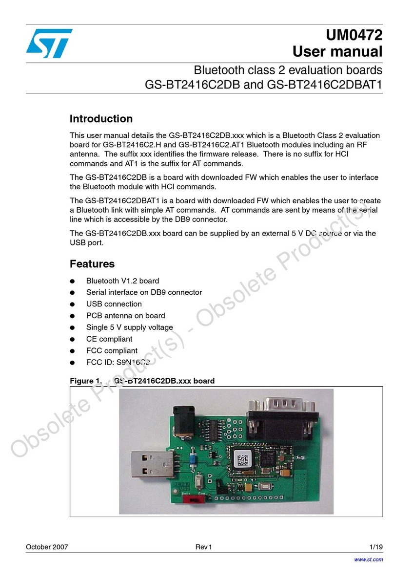
ST M24LR64-R User manual

January 2010 Doc ID 16609 Rev 1 1/49
UM0853
User manual
M24LR64-R tool kit
user guide
1 Introduction
The purpose of this user manual is to teach how to use the M24LR64-R tool kit with the
M24LRxx_Application_Software. It describes the M24LRxx_Application_Software interface
and its menus, and shows how to send commands to M24LR64-R tags.
www.st.com
Downloaded from Elcodis.com electronic components distributor

Contents UM0853
2/49 Doc ID 16609 Rev 1
Contents
1 Introduction . . . . . . . . . . . . . . . . . . . . . . . . . . . . . . . . . . . . . . . . . . . . . . . . 1
2 Tool kit descriptions . . . . . . . . . . . . . . . . . . . . . . . . . . . . . . . . . . . . . . . . . 7
2.1 Development kit . . . . . . . . . . . . . . . . . . . . . . . . . . . . . . . . . . . . . . . . . . . . . 7
2.2 M24LR64-R demonstration kit . . . . . . . . . . . . . . . . . . . . . . . . . . . . . . . . . . 9
2.3 Starter kit . . . . . . . . . . . . . . . . . . . . . . . . . . . . . . . . . . . . . . . . . . . . . . . . . 10
3 How to control the RF and I²C channels from your screen . . . . . . . . . 12
3.1 Starting M24LRxx_Application_Software . . . . . . . . . . . . . . . . . . . . . . . . . 12
3.1.1 Choosing your tool kit . . . . . . . . . . . . . . . . . . . . . . . . . . . . . . . . . . . . . . 12
3.1.2 Main menu . . . . . . . . . . . . . . . . . . . . . . . . . . . . . . . . . . . . . . . . . . . . . . . 13
3.1.3 Image Transfer Application menu . . . . . . . . . . . . . . . . . . . . . . . . . . . . . 15
3.1.4 Demo STM32-PRIMER2 menu . . . . . . . . . . . . . . . . . . . . . . . . . . . . . . . 15
3.1.5 Tools menu . . . . . . . . . . . . . . . . . . . . . . . . . . . . . . . . . . . . . . . . . . . . . . 16
3.1.6 Help menu . . . . . . . . . . . . . . . . . . . . . . . . . . . . . . . . . . . . . . . . . . . . . . . 16
3.2 RF channel commands . . . . . . . . . . . . . . . . . . . . . . . . . . . . . . . . . . . . . . 16
3.2.1 Inventory command . . . . . . . . . . . . . . . . . . . . . . . . . . . . . . . . . . . . . . . . 17
3.2.2 Get System Info command . . . . . . . . . . . . . . . . . . . . . . . . . . . . . . . . . . 18
3.2.3 Viewing RF requests and answers . . . . . . . . . . . . . . . . . . . . . . . . . . . . 18
3.2.4 Selecting the RF mode . . . . . . . . . . . . . . . . . . . . . . . . . . . . . . . . . . . . . 19
3.2.5 Managing the M24LR64-R states . . . . . . . . . . . . . . . . . . . . . . . . . . . . . 20
3.2.6 Read command . . . . . . . . . . . . . . . . . . . . . . . . . . . . . . . . . . . . . . . . . . . 20
3.2.7 Write command . . . . . . . . . . . . . . . . . . . . . . . . . . . . . . . . . . . . . . . . . . . 23
3.2.8 Write AFI command . . . . . . . . . . . . . . . . . . . . . . . . . . . . . . . . . . . . . . . . 24
3.2.9 Write DSFID command . . . . . . . . . . . . . . . . . . . . . . . . . . . . . . . . . . . . . 25
3.2.10 Lock AFI command . . . . . . . . . . . . . . . . . . . . . . . . . . . . . . . . . . . . . . . . 25
3.2.11 Lock DSFID command . . . . . . . . . . . . . . . . . . . . . . . . . . . . . . . . . . . . . . 25
3.2.12 RF password management . . . . . . . . . . . . . . . . . . . . . . . . . . . . . . . . . . 26
3.3 I²C channel . . . . . . . . . . . . . . . . . . . . . . . . . . . . . . . . . . . . . . . . . . . . . . . . 28
3.3.1 I2C READ commands . . . . . . . . . . . . . . . . . . . . . . . . . . . . . . . . . . . . . . 29
3.3.2 I2C WRITE commands . . . . . . . . . . . . . . . . . . . . . . . . . . . . . . . . . . . . . 32
3.3.3 I2C PASSWORD commands . . . . . . . . . . . . . . . . . . . . . . . . . . . . . . . . . 36
4 Data transfer management (picture demo) . . . . . . . . . . . . . . . . . . . . . . 38
Downloaded from Elcodis.com electronic components distributor

UM0853 Contents
Doc ID 16609 Rev 1 3/49
4.1 Check communication . . . . . . . . . . . . . . . . . . . . . . . . . . . . . . . . . . . . . . . 38
4.1.1 Check communication by RF . . . . . . . . . . . . . . . . . . . . . . . . . . . . . . . . . 39
4.1.2 Check communication by I2C . . . . . . . . . . . . . . . . . . . . . . . . . . . . . . . . 39
4.2 Writing a picture to your M24LR64-R . . . . . . . . . . . . . . . . . . . . . . . . . . . . 40
4.3 Read/display the M24LR64-R’s contents . . . . . . . . . . . . . . . . . . . . . . . . . 42
5 Demo application for use with DEMOKIT-M24LR-A . . . . . . . . . . . . . . . 44
5.1 Checking the RF communication . . . . . . . . . . . . . . . . . . . . . . . . . . . . . . . 44
5.2 Uploading a picture to your DEMOKIT-M24LR-A by RF . . . . . . . . . . . . . . 45
5.3 Downloading a picture from your DEMOKIT-M24LR-A by RF . . . . . . . . . 45
5.4 Check communication status . . . . . . . . . . . . . . . . . . . . . . . . . . . . . . . . . . 46
5.5 Using your STM32-PRIMER2 to read the contents of the
reference antenna by I2C . . . . . . . . . . . . . . . . . . . . . . . . . . . . . . . . . . . . . 47
6 Revision history . . . . . . . . . . . . . . . . . . . . . . . . . . . . . . . . . . . . . . . . . . . 48
Downloaded from Elcodis.com electronic components distributor

List of figures UM0853
4/49 Doc ID 16609 Rev 1
List of figures
Figure 1. RF reader (ISO 15693, RF 13.56 MHz) . . . . . . . . . . . . . . . . . . . . . . . . . . . . . . . . . . . . . . . . 7
Figure 2. External antenna. . . . . . . . . . . . . . . . . . . . . . . . . . . . . . . . . . . . . . . . . . . . . . . . . . . . . . . . . . 7
Figure 3. Serial EEPROM USB reader . . . . . . . . . . . . . . . . . . . . . . . . . . . . . . . . . . . . . . . . . . . . . . . . 8
Figure 4. I²C bus cable. . . . . . . . . . . . . . . . . . . . . . . . . . . . . . . . . . . . . . . . . . . . . . . . . . . . . . . . . . . . . 8
Figure 5. ANT1-M24LR-A reference antenna . . . . . . . . . . . . . . . . . . . . . . . . . . . . . . . . . . . . . . . . . . . 8
Figure 6. ANT2-M24LR-A reference antenna . . . . . . . . . . . . . . . . . . . . . . . . . . . . . . . . . . . . . . . . . . . 8
Figure 7. M24LR64-R in SO8 package . . . . . . . . . . . . . . . . . . . . . . . . . . . . . . . . . . . . . . . . . . . . . . . . 9
Figure 8. RF reader . . . . . . . . . . . . . . . . . . . . . . . . . . . . . . . . . . . . . . . . . . . . . . . . . . . . . . . . . . . . . . . 9
Figure 9. PRIM2-M24LR-A reference antenna . . . . . . . . . . . . . . . . . . . . . . . . . . . . . . . . . . . . . . . . . . 9
Figure 10. STM32-PRIMER2 . . . . . . . . . . . . . . . . . . . . . . . . . . . . . . . . . . . . . . . . . . . . . . . . . . . . . . . . 10
Figure 11. I²C & RF reader . . . . . . . . . . . . . . . . . . . . . . . . . . . . . . . . . . . . . . . . . . . . . . . . . . . . . . . . . 10
Figure 12. ANT1-M24LR-A reference antenna . . . . . . . . . . . . . . . . . . . . . . . . . . . . . . . . . . . . . . . . . . 11
Figure 13. ANT2-M24LR-A reference antenna . . . . . . . . . . . . . . . . . . . . . . . . . . . . . . . . . . . . . . . . . . 11
Figure 14. M24LR64-R in SO8 package . . . . . . . . . . . . . . . . . . . . . . . . . . . . . . . . . . . . . . . . . . . . . . . 11
Figure 15. Application’s opening page . . . . . . . . . . . . . . . . . . . . . . . . . . . . . . . . . . . . . . . . . . . . . . . . . 12
Figure 16. Connection check by the software . . . . . . . . . . . . . . . . . . . . . . . . . . . . . . . . . . . . . . . . . . . 13
Figure 17. Main menu window . . . . . . . . . . . . . . . . . . . . . . . . . . . . . . . . . . . . . . . . . . . . . . . . . . . . . . . 14
Figure 18. show Reader application . . . . . . . . . . . . . . . . . . . . . . . . . . . . . . . . . . . . . . . . . . . . . . . . . . 14
Figure 19. show Image Transfer application . . . . . . . . . . . . . . . . . . . . . . . . . . . . . . . . . . . . . . . . . . . . 15
Figure 20. Demo STM32-PRIMER2 menu . . . . . . . . . . . . . . . . . . . . . . . . . . . . . . . . . . . . . . . . . . . . . 15
Figure 21. Tools menu . . . . . . . . . . . . . . . . . . . . . . . . . . . . . . . . . . . . . . . . . . . . . . . . . . . . . . . . . . . . . 16
Figure 22. Help menu . . . . . . . . . . . . . . . . . . . . . . . . . . . . . . . . . . . . . . . . . . . . . . . . . . . . . . . . . . . . . 16
Figure 23. RF user interface . . . . . . . . . . . . . . . . . . . . . . . . . . . . . . . . . . . . . . . . . . . . . . . . . . . . . . . . 17
Figure 24. Inventory button . . . . . . . . . . . . . . . . . . . . . . . . . . . . . . . . . . . . . . . . . . . . . . . . . . . . . . . . . 17
Figure 25. Three tags detected . . . . . . . . . . . . . . . . . . . . . . . . . . . . . . . . . . . . . . . . . . . . . . . . . . . . . . 18
Figure 26. Specific UID selected . . . . . . . . . . . . . . . . . . . . . . . . . . . . . . . . . . . . . . . . . . . . . . . . . . . . . 18
Figure 27. Get System Info button . . . . . . . . . . . . . . . . . . . . . . . . . . . . . . . . . . . . . . . . . . . . . . . . . . . . 18
Figure 28. RF TAG REQUEST/ANSWER report . . . . . . . . . . . . . . . . . . . . . . . . . . . . . . . . . . . . . . . . . 18
Figure 29. RF request and RF answer. . . . . . . . . . . . . . . . . . . . . . . . . . . . . . . . . . . . . . . . . . . . . . . . . 19
Figure 30. Selecting the Non-addressed mode . . . . . . . . . . . . . . . . . . . . . . . . . . . . . . . . . . . . . . . . . . 19
Figure 31. Selecting the Addressed mode. . . . . . . . . . . . . . . . . . . . . . . . . . . . . . . . . . . . . . . . . . . . . . 19
Figure 32. Selecting the Select mode . . . . . . . . . . . . . . . . . . . . . . . . . . . . . . . . . . . . . . . . . . . . . . . . . 20
Figure 33. Device state management interface . . . . . . . . . . . . . . . . . . . . . . . . . . . . . . . . . . . . . . . . . . 20
Figure 34. Initiating a read operation . . . . . . . . . . . . . . . . . . . . . . . . . . . . . . . . . . . . . . . . . . . . . . . . . . 20
Figure 35. Result of the read operation - Sector 00h. . . . . . . . . . . . . . . . . . . . . . . . . . . . . . . . . . . . . . 21
Figure 36. Result of the read operation - Sector 3Fh. . . . . . . . . . . . . . . . . . . . . . . . . . . . . . . . . . . . . . 22
Figure 37. Sector 0 block 0 . . . . . . . . . . . . . . . . . . . . . . . . . . . . . . . . . . . . . . . . . . . . . . . . . . . . . . . . . 22
Figure 38. Sector 0 blocks 1 to 5 . . . . . . . . . . . . . . . . . . . . . . . . . . . . . . . . . . . . . . . . . . . . . . . . . . . . 22
Figure 39. Initiating a write operation . . . . . . . . . . . . . . . . . . . . . . . . . . . . . . . . . . . . . . . . . . . . . . . . . . 23
Figure 40. Fill with 55 . . . . . . . . . . . . . . . . . . . . . . . . . . . . . . . . . . . . . . . . . . . . . . . . . . . . . . . . . . . . . . 23
Figure 41. Get Multiple Block Security Status button. . . . . . . . . . . . . . . . . . . . . . . . . . . . . . . . . . . . . . 23
Figure 42. Security status byte for sector 07 . . . . . . . . . . . . . . . . . . . . . . . . . . . . . . . . . . . . . . . . . . . . 24
Figure 43. Security status bytes for sectors 07 and 08 . . . . . . . . . . . . . . . . . . . . . . . . . . . . . . . . . . . . 24
Figure 44. Write AFI command . . . . . . . . . . . . . . . . . . . . . . . . . . . . . . . . . . . . . . . . . . . . . . . . . . . . . . 24
Figure 45. Write DSFID command. . . . . . . . . . . . . . . . . . . . . . . . . . . . . . . . . . . . . . . . . . . . . . . . . . . . 25
Figure 46. Lock AFI command. . . . . . . . . . . . . . . . . . . . . . . . . . . . . . . . . . . . . . . . . . . . . . . . . . . . . . . 25
Figure 47. Warning before locking the AFI field. . . . . . . . . . . . . . . . . . . . . . . . . . . . . . . . . . . . . . . . . . 25
Figure 48. Lock DSFID command . . . . . . . . . . . . . . . . . . . . . . . . . . . . . . . . . . . . . . . . . . . . . . . . . . . . 25
Downloaded from Elcodis.com electronic components distributor

UM0853 List of figures
Doc ID 16609 Rev 1 5/49
Figure 49. Warning before locking the DSFID field . . . . . . . . . . . . . . . . . . . . . . . . . . . . . . . . . . . . . . . 26
Figure 50. Warning displayed on the user interface . . . . . . . . . . . . . . . . . . . . . . . . . . . . . . . . . . . . . . 26
Figure 51. Present-sector Password command . . . . . . . . . . . . . . . . . . . . . . . . . . . . . . . . . . . . . . . . . . 27
Figure 52. Present-sector Password command successful . . . . . . . . . . . . . . . . . . . . . . . . . . . . . . . . . 27
Figure 53. Present-sector Password command error . . . . . . . . . . . . . . . . . . . . . . . . . . . . . . . . . . . . . 27
Figure 54. Write-sector Password command. . . . . . . . . . . . . . . . . . . . . . . . . . . . . . . . . . . . . . . . . . . . 27
Figure 55. Warning before changing the password . . . . . . . . . . . . . . . . . . . . . . . . . . . . . . . . . . . . . . . 27
Figure 56. Write-sector Password command successful . . . . . . . . . . . . . . . . . . . . . . . . . . . . . . . . . . . 28
Figure 57. Write-sector Password command error . . . . . . . . . . . . . . . . . . . . . . . . . . . . . . . . . . . . . . . 28
Figure 58. Lock-sector Password command . . . . . . . . . . . . . . . . . . . . . . . . . . . . . . . . . . . . . . . . . . . . 28
Figure 59. Lock-sector Password command successful . . . . . . . . . . . . . . . . . . . . . . . . . . . . . . . . . . . 28
Figure 60. Lock-sector Password command error . . . . . . . . . . . . . . . . . . . . . . . . . . . . . . . . . . . . . . . . 28
Figure 61. Button to switch between the RF and I2C interfaces . . . . . . . . . . . . . . . . . . . . . . . . . . . . . 28
Figure 62. I2C User Interface window . . . . . . . . . . . . . . . . . . . . . . . . . . . . . . . . . . . . . . . . . . . . . . . . . 29
Figure 63. Reading the memory array . . . . . . . . . . . . . . . . . . . . . . . . . . . . . . . . . . . . . . . . . . . . . . . . . 29
Figure 64. Result of a Read operation to the memory array . . . . . . . . . . . . . . . . . . . . . . . . . . . . . . . . 30
Figure 65. Reading the sector security status . . . . . . . . . . . . . . . . . . . . . . . . . . . . . . . . . . . . . . . . . . . 30
Figure 66. Result of the read sector security status operation. . . . . . . . . . . . . . . . . . . . . . . . . . . . . . . 31
Figure 67. Reading the I2C_Write_Lock bit area. . . . . . . . . . . . . . . . . . . . . . . . . . . . . . . . . . . . . . . . . 31
Figure 68. Result of the I2C_Write_Lock bit area read operation . . . . . . . . . . . . . . . . . . . . . . . . . . . . 31
Figure 69. Reading the system parameter sector . . . . . . . . . . . . . . . . . . . . . . . . . . . . . . . . . . . . . . . . 32
Figure 70. Result of the read system parameter sector operation . . . . . . . . . . . . . . . . . . . . . . . . . . . . 32
Figure 71. Writing to the memory array . . . . . . . . . . . . . . . . . . . . . . . . . . . . . . . . . . . . . . . . . . . . . . . . 32
Figure 72. Write cycle successful . . . . . . . . . . . . . . . . . . . . . . . . . . . . . . . . . . . . . . . . . . . . . . . . . . . . 33
Figure 73. Write cycle failed (no write cycle detected). . . . . . . . . . . . . . . . . . . . . . . . . . . . . . . . . . . . . 33
Figure 74. Result of the Write operation (003C) . . . . . . . . . . . . . . . . . . . . . . . . . . . . . . . . . . . . . . . . . 33
Figure 75. Page Size field . . . . . . . . . . . . . . . . . . . . . . . . . . . . . . . . . . . . . . . . . . . . . . . . . . . . . . . . . . 33
Figure 76. Writing A1 to the memory array . . . . . . . . . . . . . . . . . . . . . . . . . . . . . . . . . . . . . . . . . . . . . 34
Figure 77. Writing to the sector security status area . . . . . . . . . . . . . . . . . . . . . . . . . . . . . . . . . . . . . . 34
Figure 78. Result of the write to sector security status area operation . . . . . . . . . . . . . . . . . . . . . . . . 35
Figure 79. Writing to the I2C_Write_Lock bit area . . . . . . . . . . . . . . . . . . . . . . . . . . . . . . . . . . . . . . . . 35
Figure 80. Result of the write to I2C_Write_Lock bit area operation . . . . . . . . . . . . . . . . . . . . . . . . . . 35
Figure 81. Issuing an I2C Present Password command . . . . . . . . . . . . . . . . . . . . . . . . . . . . . . . . . . . 36
Figure 82. Issuing an I2C Write Password command . . . . . . . . . . . . . . . . . . . . . . . . . . . . . . . . . . . . . 36
Figure 83. Warning . . . . . . . . . . . . . . . . . . . . . . . . . . . . . . . . . . . . . . . . . . . . . . . . . . . . . . . . . . . . . . . 37
Figure 84. Write Password cycle successful . . . . . . . . . . . . . . . . . . . . . . . . . . . . . . . . . . . . . . . . . . . . 37
Figure 85. Write Password cycle failed (no cycle detected). . . . . . . . . . . . . . . . . . . . . . . . . . . . . . . . . 37
Figure 86. Show Image Transfer Application window . . . . . . . . . . . . . . . . . . . . . . . . . . . . . . . . . . . . . 38
Figure 87. Check communication tool . . . . . . . . . . . . . . . . . . . . . . . . . . . . . . . . . . . . . . . . . . . . . . . . . 38
Figure 88. RF communication between the tag and the reader is OK . . . . . . . . . . . . . . . . . . . . . . . . . 39
Figure 89. No RF communication between the tag and the reader . . . . . . . . . . . . . . . . . . . . . . . . . . . 39
Figure 90. I2C communication between the tag and the reader is OK . . . . . . . . . . . . . . . . . . . . . . . . 39
Figure 91. Failed upload by I2C . . . . . . . . . . . . . . . . . . . . . . . . . . . . . . . . . . . . . . . . . . . . . . . . . . . . . . 39
Figure 92. WRITE PICTURE TO M24LR64 . . . . . . . . . . . . . . . . . . . . . . . . . . . . . . . . . . . . . . . . . . . . . 40
Figure 93. Picture to be uploaded . . . . . . . . . . . . . . . . . . . . . . . . . . . . . . . . . . . . . . . . . . . . . . . . . . . . 40
Figure 94. Selecting I2C to upload the picture. . . . . . . . . . . . . . . . . . . . . . . . . . . . . . . . . . . . . . . . . . . 40
Figure 95. Uploading the picture by I2C . . . . . . . . . . . . . . . . . . . . . . . . . . . . . . . . . . . . . . . . . . . . . . . 41
Figure 96. Selecting RF to upload the picture . . . . . . . . . . . . . . . . . . . . . . . . . . . . . . . . . . . . . . . . . . . 41
Figure 97. Uploading the picture by RF . . . . . . . . . . . . . . . . . . . . . . . . . . . . . . . . . . . . . . . . . . . . . . . . 41
Figure 98. I2C upload process successful . . . . . . . . . . . . . . . . . . . . . . . . . . . . . . . . . . . . . . . . . . . . . . 41
Figure 99. I2C upload process failed . . . . . . . . . . . . . . . . . . . . . . . . . . . . . . . . . . . . . . . . . . . . . . . . . . 41
Figure 100. RF upload process successful . . . . . . . . . . . . . . . . . . . . . . . . . . . . . . . . . . . . . . . . . . . . . . 41
Downloaded from Elcodis.com electronic components distributor

List of figures UM0853
6/49 Doc ID 16609 Rev 1
Figure 101. RF upload process failed . . . . . . . . . . . . . . . . . . . . . . . . . . . . . . . . . . . . . . . . . . . . . . . . . . 42
Figure 102. READ M24LR64 CONTENT interface . . . . . . . . . . . . . . . . . . . . . . . . . . . . . . . . . . . . . . . . 42
Figure 103. Selecting I2C to download the picture . . . . . . . . . . . . . . . . . . . . . . . . . . . . . . . . . . . . . . . . 42
Figure 104. Downloading the picture by I2C . . . . . . . . . . . . . . . . . . . . . . . . . . . . . . . . . . . . . . . . . . . . . 42
Figure 105. Selecting RF to download the picture . . . . . . . . . . . . . . . . . . . . . . . . . . . . . . . . . . . . . . . . . 43
Figure 106. Downloading the picture by RF. . . . . . . . . . . . . . . . . . . . . . . . . . . . . . . . . . . . . . . . . . . . . . 43
Figure 107. Progress bar . . . . . . . . . . . . . . . . . . . . . . . . . . . . . . . . . . . . . . . . . . . . . . . . . . . . . . . . . . . . 43
Figure 108. The ST logo is displayed . . . . . . . . . . . . . . . . . . . . . . . . . . . . . . . . . . . . . . . . . . . . . . . . . . 43
Figure 109. Error message . . . . . . . . . . . . . . . . . . . . . . . . . . . . . . . . . . . . . . . . . . . . . . . . . . . . . . . . . . 43
Figure 110. Demo STM32-PRIMER2 application window . . . . . . . . . . . . . . . . . . . . . . . . . . . . . . . . . . . 44
Figure 111. Check RF communication button . . . . . . . . . . . . . . . . . . . . . . . . . . . . . . . . . . . . . . . . . . . . 44
Figure 112. RF communication ongoing between reader and reference antenna . . . . . . . . . . . . . . . . . 44
Figure 113. No RF communication between reader and reference antenna . . . . . . . . . . . . . . . . . . . . . 44
Figure 114. Upload frame . . . . . . . . . . . . . . . . . . . . . . . . . . . . . . . . . . . . . . . . . . . . . . . . . . . . . . . . . . . 45
Figure 115. Click to download Picture button . . . . . . . . . . . . . . . . . . . . . . . . . . . . . . . . . . . . . . . . . . . . 45
Figure 116. HELLO WORLD picture downloaded . . . . . . . . . . . . . . . . . . . . . . . . . . . . . . . . . . . . . . . . . 46
Figure 117. ST logo downloaded . . . . . . . . . . . . . . . . . . . . . . . . . . . . . . . . . . . . . . . . . . . . . . . . . . . . . . 46
Figure 118. Upload/download process going smoothly . . . . . . . . . . . . . . . . . . . . . . . . . . . . . . . . . . . . . 46
Figure 119. Upload/download process with errors. . . . . . . . . . . . . . . . . . . . . . . . . . . . . . . . . . . . . . . . . 46
Downloaded from Elcodis.com electronic components distributor

UM0853 Tool kit descriptions
Doc ID 16609 Rev 1 7/49
2 Tool kit descriptions
2.1 Development kit
Ordering information: DEVKIT-M24LR-A
The development kit contains:
●a middle-range RF reader (ISO 15693, RF 13.56 MHz) interfaced via the USB bus and
an external power supply to have a greater read range. Figure 1 shows the RF reader.
●an external antenna, shown in Figure 2.
●a serial EEPROM USB reader, shown in Figure 3: it is an I²C bus reader (interfaced via
the USB bus).
●an I²C bus cable to connect the serial EEPROM USB reader to the I2C bus of the
reference antenna. Figure 4 shows the cable to use.
●M24LR64-R reference antennas:
– ANT1-M24LR-A shown in Figure 5:
RF antenna size: 75 mm × 45 mm (2.9 in × 1.77 in)
– ANT2-M24LR-A shown in Figure 6:
RF antenna size: 20 mm × 40 mm (0.79 in × 1.57 in)
●M24LR64-R samples in SO8 package (see Figure 7)
Figure 1. RF reader (ISO 15693, RF 13.56 MHz)
Figure 2. External antenna
ai17541
Downloaded from Elcodis.com electronic components distributor

Tool kit descriptions UM0853
8/49 Doc ID 16609 Rev 1
Figure 3. Serial EEPROM USB reader
Figure 4. I²C bus cable
Figure 5. ANT1-M24LR-A reference antenna
Figure 6. ANT2-M24LR-A reference antenna
2&ANTENNA
-,22CHIP
)#CONNECTOR
6##6333#,3$! AI
Downloaded from Elcodis.com electronic components distributor

UM0853 Tool kit descriptions
Doc ID 16609 Rev 1 9/49
Figure 7. M24LR64-R in SO8 package
2.2 M24LR64-R demonstration kit
Ordering information: DEMOKIT-M24LR-A
The demonstration kit contains:
●a middle-range RF reader (ISO 15693, RF 13.56 MHz) interfaced via the USB bus,
shown in Figure 8
●an M24LR64-R’s reference antenna: PRIM2-M24LR-A shown in Figure 9
RF antenna size: 20 mm × 40 mm (0.79 in x 1.57 in)
●Optional: STM32-PRIMER2 (to be ordered separately) shown in Figure 10
Figure 8. RF reader
Figure 9. PRIM2-M24LR-A reference antenna
2&ANTENNA
!.4-,2!DIMENSION -,22CHIP
/PTIONAL
)#CONNECTOR
6##6333#,3$!
%XTERNALCONNECTOR
FOR02)-%2
AI
Downloaded from Elcodis.com electronic components distributor

Tool kit descriptions UM0853
10/49 Doc ID 16609 Rev 1
Figure 10. STM32-PRIMER2
1. Not included in the kit, to be ordered separately.
2.3 Starter kit
Ordering information: STARTKIT-M24LR-A
The starter kit contains:
●a short-range RF reader (ISO 15693, RF 13.56 MHz), interfaced via the USB bus
(including the external I²C bus cable + connector) illustrated in Figure 11
●M24LR64-R’s reference antennas:
– ANT1-M24LR-A shown in Figure 12: RF antenna size: 75 mm × 45 mm (2.9 in ×
1.77 in)
– ANT2-M24LR-A shown in Figure 13: RF antenna size: 20 mm × 40 mm (0.79 in ×
1.57 in)
●M24LR64-R samples in SO8 package (see Figure 7)
Figure 11. I²C & RF reader
Downloaded from Elcodis.com electronic components distributor

How to control the RF and I²C channels from your screen UM0853
12/49 Doc ID 16609 Rev 1
3 How to control the RF and I²C channels from your
screen
3.1 Starting M24LRxx_Application_Software
Before starting, you must have:
●previously installed all the drivers. For how to install the required drivers, please refer to
UM0863: “M24LR64-R tool driver install guide”
●connected the reader’s USB cable
3.1.1 Choosing your tool kit
On the PC desktop, double click on the M24LRxx_Application_Software icon. On launching
the software, you will be prompted to select the kit you wish to use as shown in Figure 15.
Figure 15. Application’s opening page
Select your kit from the list below and press the OK button:
●STARTER KIT
●DEMO KIT (USB based)
●DEMO KIT (based on the RS232 port - old version)
●DEVELOPMENT KIT
If you select DEMO KIT (USB based), you can also play with the SERIAL EEPROM USB
reader by checking the box to add the Serial EEPROM USB reader.
Downloaded from Elcodis.com electronic components distributor

UM0853 How to control the RF and I²C channels from your screen
Doc ID 16609 Rev 1 13/49
Once the kit has been selected, the software checks that the selected readers are well
connected. A progress bar appears during the check as shown in Figure 16.
Figure 16. Connection check by the software
If a problem occurs, a window appears to indicate what the problem is:
●If the development kit is used, the problem could be:
– medium-range RF reader not plugged in the USB port
– medium-range RF reader driver not installed
– I²C bus reader not plugged in the USB port
– I²C bus reader driver not installed
●If the demo kit is used, the problem could be:
– medium-range RF reader not plugged in the USB port
– medium-range RF reader driver not installed
●If the starter kit is used, the problem could be:
– Short-range RF reader not plugged in the USB port
– Short-range RF reader driver not installed
3.1.2 Main menu
If all the drivers have been installed correctly, and the selected readers have been plugged,
the window shown in Figure 17 appears.
The connection status of the readers as well as the version of the software are displayed at
the bottom of the window.
Downloaded from Elcodis.com electronic components distributor

How to control the RF and I²C channels from your screen UM0853
14/49 Doc ID 16609 Rev 1
Figure 17. Main menu window
You can use the menu at the top of the window to select several applications:
Reader Application menu
Select show Reader application (Figure 18) to manage all the I²C and RF functions of the
M24LR64-R.
Figure 18. show Reader application
Downloaded from Elcodis.com electronic components distributor

UM0853 How to control the RF and I²C channels from your screen
Doc ID 16609 Rev 1 15/49
3.1.3 Image Transfer Application menu
Figure 19 shows the Image Transfer Application menu.
Select show Image Transfer application to upload or download a picture to or from the
M24LR64-R by RF or I²C.
Figure 19. show Image Transfer application
3.1.4 Demo STM32-PRIMER2 menu
Figure 20 shows the Demo STM32-PRIMER2 menu.
Select show Demo STM32-PRIMER2 to upload or download a picture to or from the
M24LR64-R by RF.
Pictures are formatted to be usable by the “Dual EE” firmware of your STM32-PRIMER2
demo.
Refer to UM0850 for details on how to use Dual EE.
Figure 20. Demo STM32-PRIMER2 menu
Downloaded from Elcodis.com electronic components distributor

How to control the RF and I²C channels from your screen UM0853
16/49 Doc ID 16609 Rev 1
3.1.5 Tools menu
Figure 21 shows the Tools menu.
Select stop animation to stop the animation in the reader application interface.
Figure 21. Tools menu
3.1.6 Help menu
Figure 22 shows the Help menu:
●Open *.bin file with BinEdit gives you access to a freeware for reading binary files
(*.bin format).
●Change background color allows you to change the color of the main window.
●About provides information about the software.
Figure 22. Help menu
3.2 RF channel commands
Select show Reader Application in the main menu. The RF user interface opens. It is
shown in Figure 23. With this interface you can send any command to the M24LR64-R tag
present in the RF reader field.
Downloaded from Elcodis.com electronic components distributor

UM0853 How to control the RF and I²C channels from your screen
Doc ID 16609 Rev 1 17/49
The Show I2C Commands button is used to switch from the RF user interface to the I²C
user interface.
Figure 23. RF user interface
3.2.1 Inventory command
The Inventory button launches an Inventory command and thus detects the tags present in
the RF field. The command is associated with an anticollision algorithm to detect each tag
individually (see Figure 25).
The Loop option is used to loop on inventory commands. It is selected (or deselected) by
checking (or unchecking) the box next to Loop.
Figure 24. Inventory button
Downloaded from Elcodis.com electronic components distributor

How to control the RF and I²C channels from your screen UM0853
18/49 Doc ID 16609 Rev 1
Figure 25. Three tags detected
You can select a tag in the list of detected UIDs by clicking on the desired UID in the list as
shown in Figure 26. The selected UID will then be used in all RF requests sent in Addressed
mode.
Figure 26. Specific UID selected
3.2.2 Get System Info command
The Get System Info button launches a Get System Info command, thus filling the System
info fields.
Figure 27. Get System Info button
3.2.3 Viewing RF requests and answers
Figure 28. RF TAG REQUEST/ANSWER report
The RF TAG REQUEST report button shows the RF request sent by the RF reader to the
tag.
Downloaded from Elcodis.com electronic components distributor

UM0853 How to control the RF and I²C channels from your screen
Doc ID 16609 Rev 1 19/49
The RF TAG ANSWER report button shows the RF answer from the tag, detected by the
RF reader.
Figure 29 shows an example of a reader’s RF request and the corresponding answer from
the tag.
Figure 29. RF request and RF answer
The RF read request is at address 0000. The RF answer is the read data: FF D8 FF E0.
3.2.4 Selecting the RF mode
The RF ISO 15693 protocol allows the user to communicate in RF in three different modes:
the Non-addressed mode, the Addressed mode and the Select mode. For further details,
please refer to the M24LR64-R datasheet.
The Non-addressed, Addressed or Select mode can be selected by clicking on the desired
mode as shown in Figure 30, Figure 31 or Figure 32.
Non-addressed mode
Selecting the Non-addressed mode clears the bits 5 and 6 in the Request_flags of the RF
request (bit 5 = 0, bit 6 = 0).
The request is executed by any M24LR64-R device (please refer to the M24LR64-R
datasheet for details).
Figure 30. Selecting the Non-addressed mode
Addressed mode
Selecting the Addressed mode clears bit 5 and sets bit 6 in the Request_flags of the RF
request (bit 5 = 0, bit 6 = 1).
The request is addressed. The UID field is present (please refer to the M24LR64-R
datasheet for details).
After an Inventory command (see Section 3.2.1: Inventory command), you will be able to
click on an UID to select a specific tag. The desired UID will be sent with the request if the
Addressed mode is chosen.
If no specific UID tag is selected, the device sends “00 00 00 00 00 00 00 00” instead of the
UID value.
Figure 31. Selecting the Addressed mode
Downloaded from Elcodis.com electronic components distributor

How to control the RF and I²C channels from your screen UM0853
20/49 Doc ID 16609 Rev 1
Select mode
Selecting the Select mode sets bit 5 and clears bit 6 in the Request_flags of the RF request
(bit 5 = 1 and bit 6 = 0).
The request is executed only by the M24LR64-R device in the Select State (please refer to
the M24LR64-R datasheet for details).
To select a tag, refer to the SELECT paragraph below, and to the M24LR64-R datasheet
(Select paragraph).
Figure 32. Selecting the Select mode
3.2.5 Managing the M24LR64-R states
The M24LR64-R can be in different states: Power-off, Ready, Quiet and Selected (refer to
the M24LR64-R datasheet for details).
The interface shown in Figure 33 is used to send three types of RF request to place the
M24LR64-R in one out of three specific states: Selected, Quiet and Ready.
Figure 33. Device state management interface
SELECT
The SELECT button is used to send a Select RF request with the UID of a specific tag
(Section 3.2.1: Inventory command) (refer to the M24LR64-R datasheet for details).
If no tag was selected after the Inventory request, the device sends “00 00 00 00 00 00 00
00” instead of the UID value.
STAY QUIET
The STAY QUIET button is used to send a Stay Quiet RF request (refer to the M24LR64-R
datasheet for details).
RESET TO READY
The RESET TO READY button is used to send a Reset to Ready RF request (refer to the
M24LR64-R datasheet for details).
3.2.6 Read command
Figure 34. Initiating a read operation
Downloaded from Elcodis.com electronic components distributor
Other manuals for M24LR64-R
1
Table of contents
Other ST Motherboard manuals

ST
ST ST7LIT15BY0 User manual

ST
ST STEVAL-AKI001V1 User manual

ST
ST EVAL-RHRICL1ATV1 User manual

ST
ST STM32F746G-DISCO User manual

ST
ST STM3210B-EVAL User manual

ST
ST STM3240G-EVAL User manual

ST
ST STM32L476G-EVAL User manual

ST
ST STEVAL-SPIN3202 User manual

ST
ST STM3241G-EVAL User manual

ST
ST EVAL-L9960 User manual

ST
ST ST72F651 User manual

ST
ST EVAL-L99ASC03 User manual

ST
ST STM32CubeH7 User manual

ST
ST STM3210E-EVAL User manual

ST
ST 32L100CDISCOVERY User manual

ST
ST STM320518-EVAL User manual

ST
ST STFPC311 User manual

ST
ST STEVAL-USBPD45H Administrator Guide

ST
ST SPC56B-DIS User manual

ST
ST STEVAL-ISF003V1 User manual