ST STFPC311 User manual

March 2006 Rev 1 1/25
UM0213
User Manual
STFPC311 Evaluation Board
Hardware Description and User Guide
Introduction
The STFPC311 is an evaluation board designed for quickand easyevaluation of STFPC311
Vacuum Fluorescent Display (VFD) Controller. The key features include:
■17-segment, 11-digit VFD,
■15 programmable Front Panel keys,
■2 switches,
■4 LEDs,
■2 LEDs to display Standby and Mute status,
■1 InfraRed (IR) Connector for remote control (RC),
■Parallel Port for communication with PC,
■External power supply to power up the controller and VFD Filament, and
■STFPC311 Graphical User Interface (GUI) to demonstrate communication to the VFD
controller as it has been interfaced with a micro controller.
The evaluation board package includes:
■1 STFPC311 board (see
Figure 1
),
■STFPC311 GUI, and
■User manual.
Figure 1. STFPC311 Evaluation Board v0.1
www.st.com
www.BDTIC.com/ST

Table of Contents UM0213 - User Manual
2/25
Table of Contents
1 Getting Started . . . . . . . . . . . . . . . . . . . . . . . . . . . . . . . . . . . . . . . . . . . . . 4
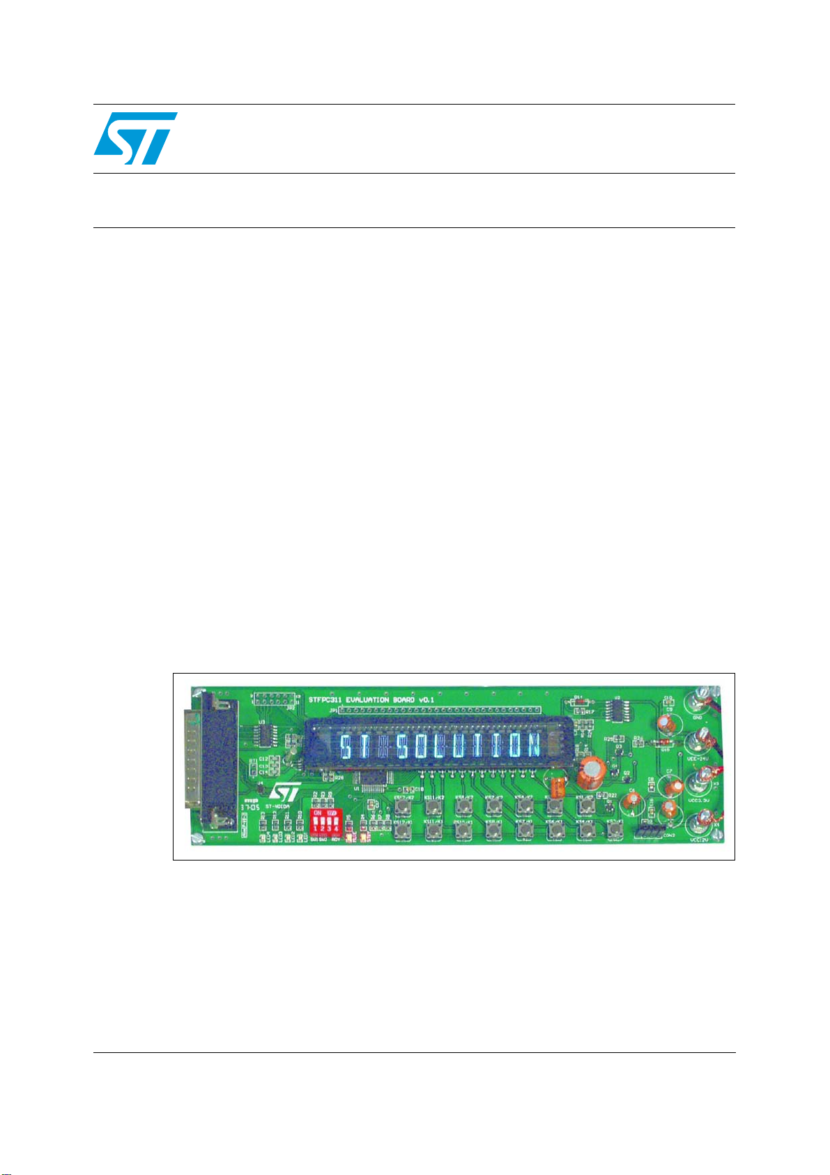
1.1 STFPC311 Demo Board Layout . . . . . . . . . . . . . . . . . . . . . . . . . . . . . . . . . 4
1.2 Software Installation . . . . . . . . . . . . . . . . . . . . . . . . . . . . . . . . . . . . . . . . . . 5
1.3 Connecting the Board . . . . . . . . . . . . . . . . . . . . . . . . . . . . . . . . . . . . . . . . . 5
2 Starting the Demo Application . . . . . . . . . . . . . . . . . . . . . . . . . . . . . . . . . 6
2.1 WDT AND STANDBY Tab . . . . . . . . . . . . . . . . . . . . . . . . . . . . . . . . . . . . . 6
2.2 COMMAND Tab . . . . . . . . . . . . . . . . . . . . . . . . . . . . . . . . . . . . . . . . . . . . . 8
2.2.1 Configuring the Display . . . . . . . . . . . . . . . . . . . . . . . . . . . . . . . . . . . . . . 8
2.3 WRITE DISPLAY MEMORY Tab . . . . . . . . . . . . . . . . . . . . . . . . . . . . . . . . 9
2.4 Returning to the COMMAND Tab . . . . . . . . . . . . . . . . . . . . . . . . . . . . . . . 10
2.4.1 WRITE LED PORTS . . . . . . . . . . . . . . . . . . . . . . . . . . . . . . . . . . . . . . . 10
2.4.2 READ SWITCHES . . . . . . . . . . . . . . . . . . . . . . . . . . . . . . . . . . . . . . . . . 10
2.4.3 Setting the READ Frequency . . . . . . . . . . . . . . . . . . . . . . . . . . . . . . . . . 10
2.5 RC and HOTKEYS CONFIG Tab . . . . . . . . . . . . . . . . . . . . . . . . . . . . . . . 11
2.5.1 Selecting the Remote Control Protocol . . . . . . . . . . . . . . . . . . . . . . . . . 11
2.5.2 Device Address Setting . . . . . . . . . . . . . . . . . . . . . . . . . . . . . . . . . . . . . 11
2.5.3 RC Hot Key Configuration . . . . . . . . . . . . . . . . . . . . . . . . . . . . . . . . . . . 11
2.5.4 Front Panel Hotkeys . . . . . . . . . . . . . . . . . . . . . . . . . . . . . . . . . . . . . . . . 12
2.5.5 STANDBY and Wake-up Sequence . . . . . . . . . . . . . . . . . . . . . . . . . . . . 12
2.6 RTC Tab . . . . . . . . . . . . . . . . . . . . . . . . . . . . . . . . . . . . . . . . . . . . . . . . . . 13
Appendix A Remote Control Protocols. . . . . . . . . . . . . . . . . . . . . . . . . . . . . . . . . 14
A.1 RC5 Protocol Key Interpretation . . . . . . . . . . . . . . . . . . . . . . . . . . . . . . . . 14
A.2 RC5 Hot Key Configuration. . . . . . . . . . . . . . . . . . . . . . . . . . . . . . . . . . . . 15
A.3 RC6 Protocol Key Interpretation . . . . . . . . . . . . . . . . . . . . . . . . . . . . . . . . 17
A.4 RC6 Hot Key Configuration. . . . . . . . . . . . . . . . . . . . . . . . . . . . . . . . . . . . 18
A.5 NEC Protocol Key Interpretation. . . . . . . . . . . . . . . . . . . . . . . . . . . . . . . . 20
A.6 NEC Hot Key Configuration. . . . . . . . . . . . . . . . . . . . . . . . . . . . . . . . . . . . 21
Appendix B Front Panel Key Banks . . . . . . . . . . . . . . . . . . . . . . . . . . . . . . . . . . . 23
3 Revision History . . . . . . . . . . . . . . . . . . . . . . . . . . . . . . . . . . . . . . . . . . . 24
www.BDTIC.com/ST

UM0213 - User Manual List of Figures
3/25
List of Figures
Figure 1. STFPC311 Evaluation Board v0.1 . . . . . . . . . . . . . . . . . . . . . . . . . . . . . . . . . . . . . . . . . . . . 1
Figure 2. STFPC311 Evaluation (Demo) Board Layout. . . . . . . . . . . . . . . . . . . . . . . . . . . . . . . . . . . . 4
Figure 3. Power Supply Connection . . . . . . . . . . . . . . . . . . . . . . . . . . . . . . . . . . . . . . . . . . . . . . . . . . 5
Figure 4. Configure Parallel Port . . . . . . . . . . . . . . . . . . . . . . . . . . . . . . . . . . . . . . . . . . . . . . . . . . . . . 6
Figure 5. READY HIGH Selection . . . . . . . . . . . . . . . . . . . . . . . . . . . . . . . . . . . . . . . . . . . . . . . . . . . . 7
Figure 6. COMMAND Tab for Display Configuration - Clicked ON . . . . . . . . . . . . . . . . . . . . . . . . . . . 8
Figure 7. VFD Filament Data Display Selection. . . . . . . . . . . . . . . . . . . . . . . . . . . . . . . . . . . . . . . . . . 9
Figure 8. Command Tab Options. . . . . . . . . . . . . . . . . . . . . . . . . . . . . . . . . . . . . . . . . . . . . . . . . . . . 10
Figure 9. Front Panel Hot Key Configuration - as STANDBY . . . . . . . . . . . . . . . . . . . . . . . . . . . . . . 12
Figure 10. Setting the Alarm Using the RTC . . . . . . . . . . . . . . . . . . . . . . . . . . . . . . . . . . . . . . . . . . . . 13
Figure 11. Reading the RC5 STANDBY Data . . . . . . . . . . . . . . . . . . . . . . . . . . . . . . . . . . . . . . . . . . . 14
Figure 12. RC5-based Remote Control STANDBY Configuration. . . . . . . . . . . . . . . . . . . . . . . . . . . . 15
Figure 13. RC5 Protocol STANDBY Key Waveforms . . . . . . . . . . . . . . . . . . . . . . . . . . . . . . . . . . . . . 16
Figure 14. Reading the RC6 STANDBY Data . . . . . . . . . . . . . . . . . . . . . . . . . . . . . . . . . . . . . . . . . . . 17
Figure 15. RC6-based Remote Control STANDBY Configuration. . . . . . . . . . . . . . . . . . . . . . . . . . . . 18
Figure 16. RC6 Protocol STANDBY Key Waveforms . . . . . . . . . . . . . . . . . . . . . . . . . . . . . . . . . . . . . 19
Figure 17. Reading the NEC Remote Control KEY1 Data. . . . . . . . . . . . . . . . . . . . . . . . . . . . . . . . . . 20
Figure 18. NEC-based Remote Control KEY1 Configuration . . . . . . . . . . . . . . . . . . . . . . . . . . . . . . . 21
Figure 19. NEC Protocol KEY1 Code Waveforms. . . . . . . . . . . . . . . . . . . . . . . . . . . . . . . . . . . . . . . . 22
Figure 20. Bank1 Keys. . . . . . . . . . . . . . . . . . . . . . . . . . . . . . . . . . . . . . . . . . . . . . . . . . . . . . . . . . . . . 23
Figure 21. Bank2 Keys. . . . . . . . . . . . . . . . . . . . . . . . . . . . . . . . . . . . . . . . . . . . . . . . . . . . . . . . . . . . . 23
Figure 22. Bank3 Keys. . . . . . . . . . . . . . . . . . . . . . . . . . . . . . . . . . . . . . . . . . . . . . . . . . . . . . . . . . . . . 23
www.BDTIC.com/ST

Getting Started UM0213 - User Manual
4/25
1 Getting Started
The board needs to be powered externally (supply is not provided). The characteristics of an
appropriate power supply (group) are:
●–30VDC to –24VDC (drives the VFD Filament),
●3.3VDC (drives the VFD Controller),
●12VDC (drives other components, such as the transistor), and
●3 connectors with a common ground which are provided on the board (see
Figure 2
).
1.1 STFPC311 Demo Board Layout
Figure 2. STFPC311 Evaluation (Demo) Board Layout
www.BDTIC.com/ST

UM0213 - User Manual Getting Started
5/25
1.2 Software Installation
The GUI is supplied in a ZIP file, “STFPC311_GUI.ZIP”. Unzip this file to obtain the
STFPC311_GUI.exe setup file. Double-click on the setup file to install the GUI on the host
system.
1.3 Connecting the Board
1. Plug the power supply group into the board (see
Figure 3
).
2. Connect the parallel cable to the host system (see
Figure 2 on page 4
).
Figure 3. Power Supply Connection
GND
VEE –24V
VCC 3.3V
VCC 12V
AI12217
www.BDTIC.com/ST

Starting the Demo Application UM0213 - User Manual
6/25
2 Starting the Demo Application
1. Start the STFPC311_GUI.
2. Configure the parallel port (“LPTx Setting” window) using the GUI (see
Figure 4
).
3. Turn the evaluation board power ON.
4. Select the READY HIGH radio button (within 10 seconds of power-on), which is located
on the WDT and STANDBY tab (see
Figure 5 on page 7
). The Standby and Mute LEDs
on the board will light up.
Note: When the GUI is invoked for the first time, the READY HIGH radio button is
selected.
2.1 WDT AND STANDBY Tab
●The “Timer Setting” pull-down menu in the “WATCHDOG TIMER” frame enables the
user to specify the Watchdog Timer’s time-out period.
●The “Reset Timer” button is used to reset the Watchdog Timer count.
●The “WATCHDOG ACTION SETTING” frame enables the user to program the time-out
event which tells the VFD controller to either go into STANDBY mode or remain in its
current state (“No Action”) by selecting the appropriate radio buttons (see
Figure 5
).
Figure 4. Configure Parallel Port
www.BDTIC.com/ST

UM0213 - User Manual Starting the Demo Application
7/25
Figure 5. READY HIGH Selection
www.BDTIC.com/ST

Starting the Demo Application UM0213 - User Manual
10/25
2.4 Returning to the COMMAND Tab
2.4.1 WRITE LED PORTS
The “WRITE LED PORTS” frame allows the user to switch the demo board LEDs (LED1 to
LED4, respectively) ON or OFF (see
Figure 8
).
2.4.2 READ SWITCHES
Clicking on the “READ SWITCHES” button allows the user to read the status of the demo
board switches (SW1 and SW2, see
Figure 8
).
2.4.3 Setting the READ Frequency
One can select the time period after which the status of the Front Panel keys is to be read.
The same option is also available for READ RC DATA (see
Figure 8
) and RTC STATUS (see
Figure 10 on page 13
).
Figure 8. Command Tab Options
www.BDTIC.com/ST

UM0213 - User Manual Starting the Demo Application
11/25
2.5 RC and HOTKEYS CONFIG Tab
2.5.1 Selecting the Remote Control Protocol
The STFPC311 supports three Remote Control (RC) protocols, RC5, RC6, and NEC (see
Appendix A: Remote Control Protocols on page 14
for RC protocol details). Select the
appropriate protocol using radio buttons in “REMOTE CONTROL PROTOCOL” frame on the
RC AND HOTKEYS CONFIG tab (see
Figure 9 on page 12
).
The RC5 and RC6 protocols use Bi-phase modulation Manchester encoding, in which logic
transitions represent a logic high or logic low signal (see
Appendix A on page 14
for details).
The NEC protocol uses pulse distance bit encoding. A logic '1' takes 2.25ms to transmit,
while a logic '0' takes only 1.12ms. A message is started by a 9ms Auto Gain Control (AGC)
burst, which is followed by a 4.5ms space, which is then followed by the Address and
Command.
The Address and Command are transmitted twice. The second time, all of the bits are
inverted and can be used for verification of the received message.
2.5.2 Device Address Setting
The STFPC311 needs to be configured with the address of the Remote Control with which it
is intended to be interfaced. Specify the address of the Remote Control in the text box in the
“RC ADDRESS” frame on RC AND HOTKEYS CONFIG tab (see
Figure 9
). For example,
the address for the RC5 protocol is 0x00 (see
Table 1
).
2.5.3 RC Hot Key Configuration
The STFPC311 GUI supports 24 Front Panel keys, 8 of which may be programmed as RC
hot keys using check boxes in the “RC HOTKEYS CONFIGURATION” frame on RC AND
HOTKEYS CONFIG tab in
Figure 9
(see
Appendix A on page 14
). For example, the RC hot
key configuration for STANDBY for the RC5 protocol is 0x0C (see
Table 1
).
1. Different remotes using the same protocol may have different device addresses.
Table 1. RC Protocol Address and STANDBY RC Hot Key
Protocol Address(1) RC Hotkey Configuration for
STANDBY
RC5 0x00 0x0C
RC6 0x27 0x0C
NEC 0x02 0x88
www.BDTIC.com/ST

Starting the Demo Application UM0213 - User Manual
12/25
2.5.4 Front Panel Hotkeys
The “FRONT PANEL HOTKEYS” frame on the RC AND HOTKEYS CONFIG tab in
Figure 9
shows the settings used to configure the KS1/K2 key as a hot key (see
Appendix B: Front
Panel Key Banks on page 23
for more Front Panel key details).
Figure 9. Front Panel Hot Key Configuration - as STANDBY
2.5.5 STANDBY and Wake-up Sequence
●To put the VFD controller in STANDBY mode, choose the “READY LOW” option in the
“STANDBY CONTROL” frame on the WDT AND STANDBY tab.
●When the VFD controller is in STANDBY mode, there are two ways to wake-up the
controller:
a) pressing the remote control STANDBY key, and
b) pressing the Front Panel Hotkey.
●After the controller wakes up from STANDBY mode choose the “READY HIGH” option
in the “STANDBY CONTROL” frame on the WDT AND STANDBY tab within 10
seconds, otherwise, the controller will go into STANDBY mode again.
The decoded IR commands are passed on to the main processor through the serial
interface by sending 3 bytes of data. Labels in “READ RC DATA” frame on COMMAND tab
represents the 24 bits of these 3-byte data frames.
www.BDTIC.com/ST

UM0213 - User Manual Starting the Demo Application
13/25
2.6 RTC Tab
The “Time Settings” frame shows the current system date and time, but these can also be
configured by the user as well. To configure the date and time at which the RTC interrupt is
to be generated (see
Figure 10
):
1. Set the date and time in the “Alarm Settings” frame.
2. Specify the frequency at which the RTC interrupt status is to be read using the “Read
Frequency” pull-down menu in the “Status” frame.
Note: The color of IRQ label changes to green when the RTC interrupt is generated.
Note: If “Read Date/Time” check box is selected, the Time display in “Time Settings” frame
follows system time.
Figure 10. Setting the Alarm Using the RTC
www.BDTIC.com/ST

Remote Control Protocols UM0213 - User Manual
14/25
Appendix A Remote Control Protocols
A.1 RC5 Protocol Key Interpretation
Figure 11
shows the value in the 3-byte data frame when the RC5 remote control STANDBY
key is pressed.
The RC key interpretation of these bit values for the 3-byte data frames for the various
STFPC311 protocols is as follows:
●B1 to B5: Device Address
●B6: Start bit
●B7: Toggle bit
●B8-B15: Key Code Data
●B16-B24: Stuffed bits (ignored)
Note: See RC and HOTKEYS CONFIG Tab on page 11 for protocol information.
Figure 11. Reading the RC5 STANDBY Data
www.BDTIC.com/ST

UM0213 - User Manual Remote Control Protocols
15/25
A.2 RC5 Hot Key Configuration
Figure 12
shows the STFPC311 being configured to interface with the RC5 protocol-based
remote control.
The RC5 hot key addressing for STANDBY configuration is as follows:
●RC Address: 0x00
●Hot Key: STANDBY (code: 0x0C)
The RC5 protocol uses Bi-phase modulation Manchester encoding in which a low-to-high
transition represents a logic high signal, and a high-to-low transition represents a logic low
signal.
Note: See RC and HOTKEYS CONFIG Tab on page 11 for protocol information.
Figure 12. RC5-based Remote Control STANDBY Configuration
www.BDTIC.com/ST

Remote Control Protocols UM0213 - User Manual
16/25
Figure 13
shows the signal at the IR sensor output when the RC5 STANDBY key is pressed.
The output shown is an inversion of the IR signal received by the IR sensor.
Figure 13. RC5 Protocol STANDBY Key Waveforms
Start Bits Toggle
Bit 5-bit Address 6-bit Command
MSB LSB MSB LSB
11000000001100
AI12253
www.BDTIC.com/ST

UM0213 - User Manual Remote Control Protocols
17/25
A.3 RC6 Protocol Key Interpretation
Figure 14
shows the signal at the output of IR sensor when STANDBY key of RC6 remote
control is pressed.
The RC key interpretation of these bit values for the 3-byte data frames for the various
STFPC311 protocols is as follows:
●B1-B8: Device Address
●B9: Start bit
●B10: Toggle bit
●B11-B18: Key Code Data
●B19-B24: Stuffed bits (ignored)
Note: See RC and HOTKEYS CONFIG Tab on page 11 for protocol information.
Figure 14. Reading the RC6 STANDBY Data
www.BDTIC.com/ST

Remote Control Protocols UM0213 - User Manual
18/25
A.4 RC6 Hot Key Configuration
Figure 15
shows STFPC311 being configured to interface with the RC6 protocol-based
remote control.
The RC6 hot key addressing for the STANDBY configuration is as follows:
●RC Address: 0x27
●Hot Key: STANDBY (code: 0x0C)
The RC6 protocol uses Bi-phase modulation Manchester encoding in which a low-to-high
transition represents a logic low signal and a high-to-low transition represents a logic high
signal.
Note: These transitions are the opposite of those in the RC5 protocol.
Note: See RC and HOTKEYS CONFIG Tab on page 11 for protocol information.
Figure 15. RC6-based Remote Control STANDBY Configuration
www.BDTIC.com/ST

UM0213 - User Manual Remote Control Protocols
19/25
Figure 16
shows the signal at the IR sensor output when the RC6 STANDBY key is pressed.
The output shown is an inversion of the IR signal received by the IR sensor.
Figure 16. RC6 Protocol STANDBY Key Waveforms
Notes:
1. LS: Leader Start Pulse
2. SB: Start Bit
3. TR: Trailer Bit
Mode Address Data
MSB LSB MSB LSB
0
LS SB TR
00 0010011100001100
AI12254
www.BDTIC.com/ST

Remote Control Protocols UM0213 - User Manual
20/25
A.5 NEC Protocol Key Interpretation
Figure 17
shows the value in 3 byte data frame when KEY1 of NEC remote is pressed.
The RC key interpretation of these bit values for the 3-byte data frames for the various
STFPC311 protocols is as follows:
●B1-B8: Device Address
●B9: Start bit
●B10: Toggle bit
●B11-B18: Key Code Data
●B19-B24: Stuffed bits (ignored)
Note: See RC and HOTKEYS CONFIG Tab on page 11 for protocol information.
Figure 17. Reading the NEC Remote Control KEY1 Data
www.BDTIC.com/ST
Table of contents
Other ST Motherboard manuals

ST
ST P-NUCLEO-IOD01A1 User manual

ST
ST STM32100E-EVAL User manual

ST
ST EVAL-L9001 User manual

ST
ST STM32 Nucleo Installation and operating instructions

ST
ST SPC584B-DISP User manual

ST
ST STM32G4 Nucleo-32 User manual

ST
ST STM32746G-EVAL User manual

ST
ST EVAL-L99ASC03 User manual

ST
ST STM32100B-EVAL User manual

ST
ST STEVAL-ISW001V1 User manual

ST
ST STM32H7 Nucleo-144 User manual

ST
ST AEKD-AICAR1 User manual

ST
ST STSW-IDS002V1 User manual

ST
ST SPC582B-DIS User manual

ST
ST AEK-SNS-2TOFM1 User manual

ST
ST PowerSTEP01 EVLPOWERSTEP01 User manual

ST
ST NUCLEO-WB15CC User manual

ST
ST STM32G081B-EVAL User manual

ST
ST STEVAL-1PS03A User manual

ST
ST STEVAL-ICB008V1 User manual