ST UM0969 User manual

November 2010 Doc ID 17665 Rev 1 1/57
UM0969
User manual
3-phase motor control demonstration board featuring IGBT
intelligent power module STGIPS10K60A
Introduction
This document describes the 1 kW 3-phase motor control demonstration board, featuring
the STGIPS10K60A: 600 V - 10 A IGBT Intelligent power module. The demonstration board
is a 3-phase inverter for driving an induction motor or PMSM motors up to 1000 W. The main
target of this application is to show users the performance of the ST 25L-SDIP (25-lead,
small dual inline package), IPM - STGIPS10K60A.
The board has been designed to be compatible with a single-phase supply from 90 VAC to
220 VAC, or for DC voltage from 125 VDC to 350 VDC. The document is associated with the
release of the STEVAL-IHM027V1 demonstration board (see Figure 1).
Figure 1. STEVAL-IHM027V1 demonstration board
www.st.com

Contents UM0969
2/57 Doc ID 17665 Rev 1
Contents
1 System introduction . . . . . . . . . . . . . . . . . . . . . . . . . . . . . . . . . . . . . . . . . 6
1.1 Main characteristics . . . . . . . . . . . . . . . . . . . . . . . . . . . . . . . . . . . . . . . . . . 6
1.2 Target application . . . . . . . . . . . . . . . . . . . . . . . . . . . . . . . . . . . . . . . . . . . . 6
1.3 Safety and operating instructions . . . . . . . . . . . . . . . . . . . . . . . . . . . . . . . . 7
1.3.1 General terms . . . . . . . . . . . . . . . . . . . . . . . . . . . . . . . . . . . . . . . . . . . . . 7
1.3.2 Demonstration board intended use . . . . . . . . . . . . . . . . . . . . . . . . . . . . . 7
1.3.3 Demonstration board installation . . . . . . . . . . . . . . . . . . . . . . . . . . . . . . . 7
1.3.4 Electrical connections . . . . . . . . . . . . . . . . . . . . . . . . . . . . . . . . . . . . . . . 8
2 Board description . . . . . . . . . . . . . . . . . . . . . . . . . . . . . . . . . . . . . . . . . . . 9
2.1 System architecture . . . . . . . . . . . . . . . . . . . . . . . . . . . . . . . . . . . . . . . . . . 9
2.2 Board schematics . . . . . . . . . . . . . . . . . . . . . . . . . . . . . . . . . . . . . . . . . . . 10
2.3 Circuit description . . . . . . . . . . . . . . . . . . . . . . . . . . . . . . . . . . . . . . . . . . . 21
2.3.1 Power supply . . . . . . . . . . . . . . . . . . . . . . . . . . . . . . . . . . . . . . . . . . . . . 21
2.3.2 Inrush limitation . . . . . . . . . . . . . . . . . . . . . . . . . . . . . . . . . . . . . . . . . . . 21
2.3.3 Brake function . . . . . . . . . . . . . . . . . . . . . . . . . . . . . . . . . . . . . . . . . . . . 21
2.3.4 Overcurrent protection (OCP) . . . . . . . . . . . . . . . . . . . . . . . . . . . . . . . . 22
2.3.5 Current sensing amplifying network . . . . . . . . . . . . . . . . . . . . . . . . . . . . 22
2.3.6 Tachometer and Hall/encoder input . . . . . . . . . . . . . . . . . . . . . . . . . . . . 25
2.3.7 Temperature feedback and overtemperature protection (OTP) . . . . . . . 25
3 Hardware setting of the STEVAL-IHM027V1 . . . . . . . . . . . . . . . . . . . . . 27
3.1 Hardware settings with single-shunt configuration . . . . . . . . . . . . . . . . . . 27
3.2 Hardware settings with three-shunt configuration . . . . . . . . . . . . . . . . . . 28
3.3 Hardware settings for input stage . . . . . . . . . . . . . . . . . . . . . . . . . . . . . . . 29
4 Description of jumpers, test pins, and connectors . . . . . . . . . . . . . . . 30
5 Connector placement . . . . . . . . . . . . . . . . . . . . . . . . . . . . . . . . . . . . . . . 35
6 BOM list . . . . . . . . . . . . . . . . . . . . . . . . . . . . . . . . . . . . . . . . . . . . . . . . . . 36
7 PCB layout . . . . . . . . . . . . . . . . . . . . . . . . . . . . . . . . . . . . . . . . . . . . . . . . 40

UM0969 Contents
Doc ID 17665 Rev 1 3/57
8 Power losses and dissipation . . . . . . . . . . . . . . . . . . . . . . . . . . . . . . . . 44
8.1 Assumptions . . . . . . . . . . . . . . . . . . . . . . . . . . . . . . . . . . . . . . . . . . . . . . . 44
8.2 Conduction loss . . . . . . . . . . . . . . . . . . . . . . . . . . . . . . . . . . . . . . . . . . . . 44
8.3 Switching loss . . . . . . . . . . . . . . . . . . . . . . . . . . . . . . . . . . . . . . . . . . . . . . 46
8.4 Thermal impedance overview . . . . . . . . . . . . . . . . . . . . . . . . . . . . . . . . . 46
8.5 Temperature rise considerations and calculation example . . . . . . . . . . . . 48
9 Ordering information . . . . . . . . . . . . . . . . . . . . . . . . . . . . . . . . . . . . . . . 49
10 Using the STEVAL-IHM027V1 with STM32 FOC firmware library . . . . 50
11 Environmental considerations . . . . . . . . . . . . . . . . . . . . . . . . . . . . . . . . 51
12 Hardware requirements . . . . . . . . . . . . . . . . . . . . . . . . . . . . . . . . . . . . . 52
13 Software requirements . . . . . . . . . . . . . . . . . . . . . . . . . . . . . . . . . . . . . . 53
14 Conclusion . . . . . . . . . . . . . . . . . . . . . . . . . . . . . . . . . . . . . . . . . . . . . . . . 54
15 References . . . . . . . . . . . . . . . . . . . . . . . . . . . . . . . . . . . . . . . . . . . . . . . . 55
16 Revision history . . . . . . . . . . . . . . . . . . . . . . . . . . . . . . . . . . . . . . . . . . . 56

List of tables UM0969
4/57 Doc ID 17665 Rev 1
List of tables
Table 1. Jumper settings for a single-shunt or three-shunt configuration . . . . . . . . . . . . . . . . . . . . . 24
Table 2. Internal IPM NTC details (see relevant section on the STGIPS10K60A datasheet). . . . . . 26
Table 3. Jumper settings for single-shunt configuration . . . . . . . . . . . . . . . . . . . . . . . . . . . . . . . . . . 27
Table 4. Jumper settings for three-shunt configuration . . . . . . . . . . . . . . . . . . . . . . . . . . . . . . . . . . 28
Table 5. Input stage configuration details . . . . . . . . . . . . . . . . . . . . . . . . . . . . . . . . . . . . . . . . . . . . . 29
Table 6. Jumpers description . . . . . . . . . . . . . . . . . . . . . . . . . . . . . . . . . . . . . . . . . . . . . . . . . . . . . . 30
Table 7. Connector pinout description . . . . . . . . . . . . . . . . . . . . . . . . . . . . . . . . . . . . . . . . . . . . . . . 31
Table 8. Testing points description . . . . . . . . . . . . . . . . . . . . . . . . . . . . . . . . . . . . . . . . . . . . . . . . . . 34
Table 9. BOM list . . . . . . . . . . . . . . . . . . . . . . . . . . . . . . . . . . . . . . . . . . . . . . . . . . . . . . . . . . . . . . . 36
Table 10. RC - Cauer STGIPS10K60A thermal network . . . . . . . . . . . . . . . . . . . . . . . . . . . . . . . . . . 47
Table 11. Document revision history . . . . . . . . . . . . . . . . . . . . . . . . . . . . . . . . . . . . . . . . . . . . . . . . . 56

UM0969 List of figures
Doc ID 17665 Rev 1 5/57
List of figures
Figure 1. STEVAL-IHM027V1 demonstration board . . . . . . . . . . . . . . . . . . . . . . . . . . . . . . . . . . . . . . 1
Figure 2. Motor control system architecture. . . . . . . . . . . . . . . . . . . . . . . . . . . . . . . . . . . . . . . . . . . . . 9
Figure 3. Input stage with bridge schematic . . . . . . . . . . . . . . . . . . . . . . . . . . . . . . . . . . . . . . . . . . . 10
Figure 4. Bus voltage sense resistor schematic . . . . . . . . . . . . . . . . . . . . . . . . . . . . . . . . . . . . . . . . 11
Figure 5. +5 V linear schematic . . . . . . . . . . . . . . . . . . . . . . . . . . . . . . . . . . . . . . . . . . . . . . . . . . . . . 11
Figure 6. +3.3 V linear schematic . . . . . . . . . . . . . . . . . . . . . . . . . . . . . . . . . . . . . . . . . . . . . . . . . . . 12
Figure 7. Buck converter schematic. . . . . . . . . . . . . . . . . . . . . . . . . . . . . . . . . . . . . . . . . . . . . . . . . . 12
Figure 8. Thermal shutdown . . . . . . . . . . . . . . . . . . . . . . . . . . . . . . . . . . . . . . . . . . . . . . . . . . . . . . . 13
Figure 9. NTC bypass schematic. . . . . . . . . . . . . . . . . . . . . . . . . . . . . . . . . . . . . . . . . . . . . . . . . . . . 14
Figure 10. Motor output schematic . . . . . . . . . . . . . . . . . . . . . . . . . . . . . . . . . . . . . . . . . . . . . . . . . . . 14
Figure 11. +15 V auxiliary supply schematic . . . . . . . . . . . . . . . . . . . . . . . . . . . . . . . . . . . . . . . . . . . . 15
Figure 12. BEMF_daughter board schematic . . . . . . . . . . . . . . . . . . . . . . . . . . . . . . . . . . . . . . . . . . . 15
Figure 13. Motor control connector schematic . . . . . . . . . . . . . . . . . . . . . . . . . . . . . . . . . . . . . . . . . . . 15
Figure 14. Hall sensors\encoder schematic . . . . . . . . . . . . . . . . . . . . . . . . . . . . . . . . . . . . . . . . . . . . . 16
Figure 15. Tachometer sensor schematic . . . . . . . . . . . . . . . . . . . . . . . . . . . . . . . . . . . . . . . . . . . . . . 16
Figure 16. Brake control schematic . . . . . . . . . . . . . . . . . . . . . . . . . . . . . . . . . . . . . . . . . . . . . . . . . . . 17
Figure 17. STEVAL-IHM027V1 schematic. . . . . . . . . . . . . . . . . . . . . . . . . . . . . . . . . . . . . . . . . . . . . . 18
Figure 18. Current sensing A schematic . . . . . . . . . . . . . . . . . . . . . . . . . . . . . . . . . . . . . . . . . . . . . . . 18
Figure 19. Current sensing B schematic . . . . . . . . . . . . . . . . . . . . . . . . . . . . . . . . . . . . . . . . . . . . . . . 19
Figure 20. Current sensing C schematic . . . . . . . . . . . . . . . . . . . . . . . . . . . . . . . . . . . . . . . . . . . . . . . 19
Figure 21. Overcurrent\overtemperature protection schematic . . . . . . . . . . . . . . . . . . . . . . . . . . . . . . 20
Figure 22. STEVAL-IHM027V1 power supply block diagram . . . . . . . . . . . . . . . . . . . . . . . . . . . . . . . 21
Figure 23. Three-shunt configuration. . . . . . . . . . . . . . . . . . . . . . . . . . . . . . . . . . . . . . . . . . . . . . . . . . 22
Figure 24. Single-shunt configuration . . . . . . . . . . . . . . . . . . . . . . . . . . . . . . . . . . . . . . . . . . . . . . . . . 24
Figure 25. OT protection circuit . . . . . . . . . . . . . . . . . . . . . . . . . . . . . . . . . . . . . . . . . . . . . . . . . . . . . . 26
Figure 26. STEVAL-IHM027V1 input stage detail . . . . . . . . . . . . . . . . . . . . . . . . . . . . . . . . . . . . . . . . 29
Figure 27. Connector placement . . . . . . . . . . . . . . . . . . . . . . . . . . . . . . . . . . . . . . . . . . . . . . . . . . . . . 35
Figure 28. Copper tracks - top side . . . . . . . . . . . . . . . . . . . . . . . . . . . . . . . . . . . . . . . . . . . . . . . . . . . 40
Figure 29. Copper tracks - bottom side . . . . . . . . . . . . . . . . . . . . . . . . . . . . . . . . . . . . . . . . . . . . . . . . 41
Figure 30. Silk screen - top side . . . . . . . . . . . . . . . . . . . . . . . . . . . . . . . . . . . . . . . . . . . . . . . . . . . . . 42
Figure 31. Silk screen - bottom side . . . . . . . . . . . . . . . . . . . . . . . . . . . . . . . . . . . . . . . . . . . . . . . . . . 43
Figure 32. Static parameter calculations . . . . . . . . . . . . . . . . . . . . . . . . . . . . . . . . . . . . . . . . . . . . . . . 45
Figure 33. Equivalent STGIPS10K60A thermal network (CAUER models). . . . . . . . . . . . . . . . . . . . . 47
Figure 34. Maximum IC(RMS) current vs. switching frequency . . . . . . . . . . . . . . . . . . . . . . . . . . . . . . 48

System introduction UM0969
6/57 Doc ID 17665 Rev 1
1 System introduction
1.1 Main characteristics
The main characteristics of the STEVAL-IHM027V1 demonstration board are:
●ST IGBT intelligent power module: STGIPS10K60A
●Minimum input voltage 125 VDC or 90 VAC
●Maximum input voltage 350 VDC or 220 VAC
●Possibility to use external +15 V supply voltage
●Maximum output power for motor up to 1000 W
●Regenerative brake control feature
●Input inrush limitation with bypassing relay
●+15 V auxiliary power supply based on buck converter with VIPer16
●Fully populated board conception with testing points
●Motor control connector for interface with STM3210B-EVAL board and further ST motor
control dedicated kits
●Tachometer input
●Hall\encoder inputs
●Possibility to connect BEMF daughter board for sensorless six-step control of BLDC
motors
●PCB type and size:
– Material of PCB: FR-4
– Double side layout
– Copper thickness: ~45 µm
– Dimension of demonstration board: 147 mm*157 mm
1.2 Target application
●Domestic appliances
●Medical applications, fitness applications
●High power industry pumps
●Medium power fans for HVAC
●Power tools

UM0969 System introduction
Doc ID 17665 Rev 1 7/57
1.3 Safety and operating instructions
1.3.1 General terms
Warning: During assembly, testing, and normal operation, the
demonstration board poses several inherent hazards,
including bare wires, moving or rotating parts and hot
surfaces. There is a danger of serious personal injury if the
kit or components are improperly used or incorrectly
installed. The kit is not electrically isolated from the AC/DC
input. The demonstration board is directly linked to the mains
voltage. No insulation is ensured between accessible parts
and high voltage. All measuring equipment must be isolated
from the mains before powering the board. When using an
oscilloscope with the demonstration board, it must be
isolated from the AC line. This prevents shock from occurring
as a result of touching any SINGLE point in the circuit, but
does NOT prevent shock when touching two or more points
in the circuit. Do not touch the demonstration board after
disconnection from the voltage supply; several parts and
power terminals, which contain energized capacitors, must
be allowed to discharge.
All operations involving transportation, installation and use, as well as maintenance, are to
be carried out by skilled technical personnel (national accident prevention rules must be
observed). For the purpose of these basic safety instructions, “skilled technical personnel”
are considered as suitably qualified people who are familiar with the installation, use, and
maintenance of power electronic systems.
1.3.2 Demonstration board intended use
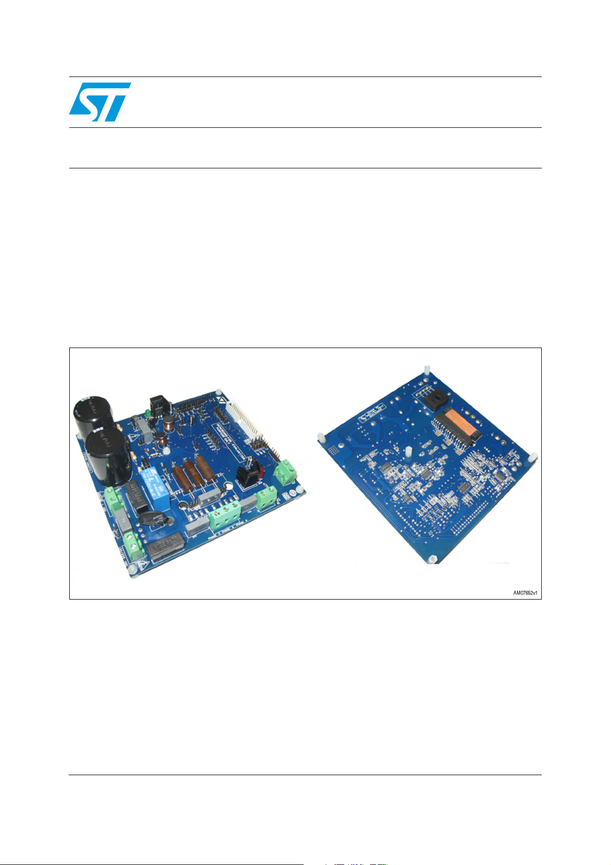
The STEVAL-IHM027V1 demonstration board is designed for demonstration purposes only
and must not be used for any commercial purposes. The technical data, as well as
information concerning power supply conditions, must be taken from the relevant
documentation and strictly observed.
1.3.3 Demonstration board installation
The installation of the demonstration board must be in accordance with the specifications
and the targeted application.
●The boards contain electro-statically sensitive components that are prone to damage
through improper use. Electrical components must not be mechanically damaged or
destroyed
●Avoid any contacts with other electronic components
●During the motor drive converters must be protected against excessive strain. In
particular, no components are to be bent or isolating distances altered during the
course of transportation or handling

System introduction UM0969
8/57 Doc ID 17665 Rev 1
1.3.4 Electrical connections
Applicable national accident prevention rules must be followed when working on the main
power supply with a motor drive. The electrical installation must be completed in accordance
with the appropriate requirements. A system architecture which supplies power to the
demonstration board must be equipped with additional control and protective devices in
accordance with the applicable safety requirements (e.g. compliance with technical
equipment and accident prevention rules).

UM0969 Board description
Doc ID 17665 Rev 1 9/57
2 Board description
2.1 System architecture
A generic motor control system can be basically schematized as the combination of three
main blocks (see Figure 2):
●Control block: the main task of this block is to accept user commands and board\motor
configuration parameters. The control block provides all digital signals to implement the
right motor driving strategy. The STM3210B-EVAL, ST demonstration board, based on
an STM32 microcontroller, can be connected to the STEVAL-IHM027V1 thanks to the
onboard motor control connector
●Power block: this is based on three-phase inverter topology. The heart of the power
block is the STGIPS10K60A integrated intelligent power module which contains all the
necessary active components. Please refer to the STGIPS10K60A datasheet (see
References 1) for more information
●Power supply block: able to work from 90 VAC to 220 VAC or from 125 VDC to 350
VDC. Please refer to Section 3: Hardware setting of the STEVAL-IHM027V1, to
properly set the jumpers according to the required application
Figure 2. Motor control system architecture
The STEVAL-IHM027V1 includes the power supply and the power block.

UM0969 Board description
Doc ID 17665 Rev 1 10/57
2.2 Board schematics
Figure 3. Input stage with bridge schematic
!-V
5HOD\
5HOD\
%86
6OLTAGEDOUBLER6AC
--
&
9
&
9
--
--
&
Q)9;
&
Q)9;
55
N:
5
N:
5
--
--
-
9$&
-
9$&
5
N:N:
5
N:N:
)
$
)
$
&
9
&
9
-
9'&%86
-
9'&%86
--
W
57
17&
W
57
17&
75
.($
75
.($
--
'
%5,'*(
'
%5,'*(
--
--
)
$
)
$
--

UM0969 Board description
Doc ID 17665 Rev 1 11/57
Figure 4. Bus voltage sense resistor schematic
Figure 5. +5 V linear schematic
!-V
"53
(6"US
!,,4(%2%3)34/23
!##52!#9-534"%
2
+
2
+
2
+
2
+
2
+
2
+
#
N&6?
#
N&6?
!-V
6
6
$
":8#
$
,$
'2%%.,%$
2
+
)#
,#0
6IN
'.$
6OUT
#
&6
#
&6

Board description UM0969
12/57 Doc ID 17665 Rev 1
Figure 6. +3.3 V linear schematic
Figure 7. Buck converter schematic
!-V
6
60OW
**
#
&6
#
&6
#
&6
#
&6
5 ,$$
'.$
/54
/54
).
/54
/54
!-V
%86
9
'
%=;&
'
%=;&
5
5
/
+
/
+
&
Q)9B
&
Q)9B
--
- 9,3(5212))- 9,3(5212))
&
Q)9
&
Q)9
5
QF
5
QF
8
9,3(5/1
8
9,3(5/1
6RXUFH
6RXUFH
6RXUFH
6RXUFH
&203
)%
/,0
9''
'UDLQ
'UDLQ
'UDLQ
'UDLQ
&
Q)9B
&
Q)9B
'
677+/$
'
677+/$
&
)9
&
)9
&
)9
&
)9
5
N
5
N
&
Q)9;
&
Q)9;
'
677+/
'
677+/
/
P+
/
P+
5
N
5
N
&
QF
&
QF

UM0969 Board description
Doc ID 17665 Rev 1 13/57
Figure 8. Thermal shutdown
!-V
(EATSINK4EMPERATURE
TEMP
4
4
6
7
*5-0
2
2
$
.
1
11
2

Board description UM0969
14/57 Doc ID 17665 Rev 1
Figure 9. NTC bypass schematic
Figure 10. Motor output schematic
!-V
2ELAY
2ELAY
6
)NRUSHCURR
1
342
1
342
5
2%,!9!
5
2%,!9!
$
.
$
.
2
2
2
K
2
K
2
K
2
K
!-V
0HASE#
0HASE"
0HASE!
*
0(!3%/54054

UM0969 Board description
Doc ID 17665 Rev 1 15/57
Figure 11. +15 V auxiliary supply schematic
Figure 12. BEMF_daughter board schematic
Figure 13. Motor control connector schematic
!-V
6
*
#/.
!-V
0HASE!
0HASE"
0HASE#
"53
6
6DD?M
07-6REF
*
LINEBAR
!-V
3:0B+
3:0B/
3:0B+
3:0B/
3:0B+
3:0B/
+9%XV
+HDWVLQN7HPSHUDWXUH
&XUUHQW3KDVH%
&XUUHQW3KDVH&
9
3:09UHI
0HDVXUH3KDVH$
&XUUHQW3KDVH$
0HDVXUH3KDVH&
9GGBP
)DXOW
0HDVXUH3KDVH%
93RZ
9
,QUXVKFXUU
3:0B%UDNH
-
&217
-
&217
::
:
-803
:
-803
5
N
5
N
:
-803
:
-803
5
N
5
N
5
N
5
N
5
N
5
N
5
N
5
N
'
%$5
'
%$5
5
N
5
N

Board description UM0969
16/57 Doc ID 17665 Rev 1
Figure 14. Hall sensors\encoder schematic
Figure 15. Tachometer sensor schematic
!-V
0HDVXUH3KDVH&
0HDVXUH3KDVH%
0HDVXUH3KDVH$
9GGBP
9
9GGBP
$%
+DOO
+DOO
+DOO
99
*1'
&
Q)9B
&
Q)9B
5
N
5
N
5
N
5
N
5
N
5
N
::
8 0+&
8 0+&
5
N
5
N
--
::
5
N
5
N
&
Q)9B
&
Q)9B
&
S)9B
&
S)9B
::
5
N
5
N
&
S)9B
&
S)9B
::
&
S)9B
&
S)9B
!-V
9GGBP
0HDVXUH3KDVH$
7
675
:
5
N
'
%$5
'
'
%$5
5
N
-
7$&+2
&
Q)9B
5
&
Q)9B
5
QF
5
N
&
Q)9B

UM0969 Board description
Doc ID 17665 Rev 1 17/57
Figure 16. Brake control schematic
!-V
%86
%86 %UDNHFRQWURO
3:0B%UDNH
9
9
9
9
5
5
5
N
5
N
5
N
5
N
4
675
4
675
5
N
5
N
&
S)9B
&
S)9B
5
N
5
N
67*)1&+'
4
67*)1&+'
4
5
N
5
N
5
N
5
N
&
)9
&
)9
5
QF
5
QF
4
675
4
675 4
675
4
675
5
5
4
675
4
675
&
Q)9B
&
Q)9B
5
N
5
N
5
N
5
N
4
675
4
675
-
5%UDNH
-
5%UDNH
'
%=;&9
'
%=;&9
'
%=;&9
'
%=;&9
8
76,/7
8
76,/7
5
5
5
N
5
N
5
N
5
N
5
N
5
N
5
N
5
N
5
N
5
N
/'
5('/('
/'
5('/('
5
N
5
N
5
5
4
675
4
675
5
N
5
N
&
Q9B
&
Q9B
'
677+
'
677+

Board description UM0969
18/57 Doc ID 17665 Rev 1
Figure 17. STEVAL-IHM027V1 schematic
Figure 18. Current sensing A schematic
!-V
%86
3KDVH$
3KDVH%
3KDVH&
%UDNHFRQWURO
3KDVH&
&XUUHQW3KDVH&
&XUUHQW3KDVH$
&XUUHQW3KDVH%
9
9
3:0B%/
3:0B$/
3:0B$+
0HDVXUH3KDVH&
0HDVXUH3KDVH$
0HDVXUH3KDVH%
3:0B&+
3:0B%+
3:0B&/
3KDVH$
3KDVH%
93RZ
+9%XV
,+LJK3KDVH%
,/RZ3KDVH%
,/RZ3KDVH$
,+LJK3KDVH&
,/RZ3KDVH&
,+LJK3KDVH$
9
7
3:0B&/
3:0B$+
3:0B&+
3:0B$/
3:0B%/
3:0B%+
7
$
$
%
%
7REHVROGHUHG
7REHVROGHUHG
4ESTPOINTS
34)0-34')03+!
7373
&
Q)9
&
Q)9
&
)9B
&
)9B
7373
7373
&
)9B
&
)9B
::
7373
7373
&
Q)9
&
Q)9
7373
&
)9B
&
)9B
7373
5
5
&
Q)9B
&
Q)9B
7373
7373
55
55
&
)9B
&
)9B
7373
7373
7373
5
5
&
Q)9B
&
Q)9B
::
8
67*,36.$
8
67*,36.$
2878
9%2278
/,1
+,1
9&&
3
8
(
3
9
(
2879
9%2279
3
:
(
*1'
/,1
+,1
287:
9%227:
/,1
+,1
7
7
7373
7373
7373
&
Q)9
&
Q)9
7373
7373
5
5
7373
&
Q)9B
&
Q)9B
7373
55
7373
&
)9B
&
)9B
7373
&
)9B
&
)9B
&
Q)9B
&
Q)9B
!-V
9GGBP
28723DPS
9
9
,+LJK3KDVH$
,/RZ3KDVH$
&XUUHQW3KDVH$
&
S)9B
8$
769
8$
& )9
& )9
5
N
&
S)9B
& Q)9B
& Q)9B
5
5
5
N
5
N
5
N
5
N
5
N
'
%$5
'
%$5
5

UM0969 Board description
Doc ID 17665 Rev 1 19/57
Figure 19. Current sensing B schematic
Figure 20. Current sensing C schematic
!-V
9GGBP
9
,/RZ3KDVH%
&XUUHQW3KDVH%
,+LJK3KDVH%
28723DPS
$
%
:
&
S)9B
&
5
N
5
5
N
5
N
:
5
N
N
8%
769
5
N
5
N
&
S)9B
&
S)9B
5
N
5
N
:
5
N
5
5
5
5
'
%$5
'
%$5
!-V
28723DPS
9GGBP
9
,+LJK3KDVH&
,/RZ3KDVH&
&XUUHQW3KDVH&
DOOUHVLVWRUDW
5
N
5
5
N
5
N
5 N
5
&
S)9B
&
8&
769
8&
769
5
N
&
S)9B
8'
769
5
N
5
N
'
%$5

UM0969 Board description
Doc ID 17665 Rev 1 20/57
Figure 21. Overcurrent\overtemperature protection schematic
!-V
3:0B+
3:0B/
3:0B+
3:0B/
3:0B+
3:0B/
3:0B&+
3:0B$/
3:0B%/
3:0B&/
3:0B$+
3:0B%+
9
9
9
9
)DXOW
WHPS
28723DPS
28723DPS
28723DPS
$
%
/#0PROTECTION/&&
:
-803
:
-803
' %$5' %$5
5
N
5
N
::
8
76,/7
8
76,/7
5
N
5
N
' %$5' %$5
44
&
Q)9B
&
Q)9B
&&
5
N
5
N
8
0+&05
8
0+&05
*
*1'
*
9&&
<
<
<
<
$
$
$
$
<
<
$
$
5
N
5
N
' %$5' %$5
5
N
5
N
5
.
5
.
&
S)9B
&
S)9B
5
N
5
N
' %$5' %$5
Table of contents
Other ST Motherboard manuals

ST
ST SPC574KADPT144S User manual

ST
ST STM3210E-EVAL User manual

ST
ST STEVAL-L6982CDR User manual

ST
ST STEVAL-ISB68RX User manual

ST
ST NUCLEO-F207ZG User manual

ST
ST STEVAL-SPIN3202 User manual

ST
ST VIPower VIPer22A-E Installation and operating instructions

ST
ST ST9 EPB User manual

ST
ST FDA803S User manual

ST
ST ST25RU3993-EVAL User manual

ST
ST STM32 Nucleo User manual

ST
ST EVAL-L99H02QF User manual

ST
ST STM32L152RCT6 Discovery kit User manual

ST
ST STM32H753I-EVAL User manual

ST
ST EVALSP820-XS User manual

ST
ST ST72F651 User manual

ST
ST STEVAL-PTOOL2V1 User manual

ST
ST STEVAL-IDB007V Series User manual

ST
ST STM32100E-EVAL User manual

ST
ST Nucleo STM32F302R8 User manual