ST STSW-S2LP-KNX-DK User manual

Introduction
The STSW-S2LP-KNX-DK is an evaluation package based on the S2-LP high performance ultra-low power RF transceiver and
BlueNRG-2 very low power Bluetooth Low Energy (BLE) system-on-chip. It is designed to evaluate KNX-RF communication in
the 868 MHz license-free ISM band.
The STSW-S2LP-KNX-DK package provides a software framework including KNX Tapko technologies stack (evaluation
version). The package includes application examples which allow simulating point-to-point KNX-RF protocol communication
and are compliant with the KNX ETS tool.
This software combines KNX-RF Sub-1 GHz protocol and Bluetooth LE communication in one single application (using S2-LP
and BlueNRG-2).
Getting started with the STSW-S2LP-KNX-DK software package for KNX-RF
UM2920
User manual
UM2920 - Rev 1 - September 2021
For further information contact your local STMicroelectronics sales office.
www.st.com

1Getting started
1.1 Overview
The STSW-S2LP-KNX-DK features:
• Firmware package to start evaluation of KNX-RF connectivity based on the S2-LP transceiver
• KNX-RF Tapko technology stack (evaluation license) running on the BlueNRG-2 Bluetooth® LE 5.2 wireless
SoC and STM32L0 microcontrollers
• Application example for KNX-RF and Bluetooth® LE 5.2 controller
• Application example for KNX-RF actuator
• Standalone point-to-point KNX-RF communication between two nodes
• Control and monitoring of KNX-RF devices through KNX ETS5 PC tool
• Combination of KNX-RF and Bluetooth® connectivity in one application
• Sample implementation available on X-NUCLEO-S2868A2 (or X-NUCLEO-S2868A1) expansion boards
when connected to STEVAL-IDB008V2 (BlueNRG-2 Bluetooth Low-Energy) or NUCLEO-L073RZ
development boards
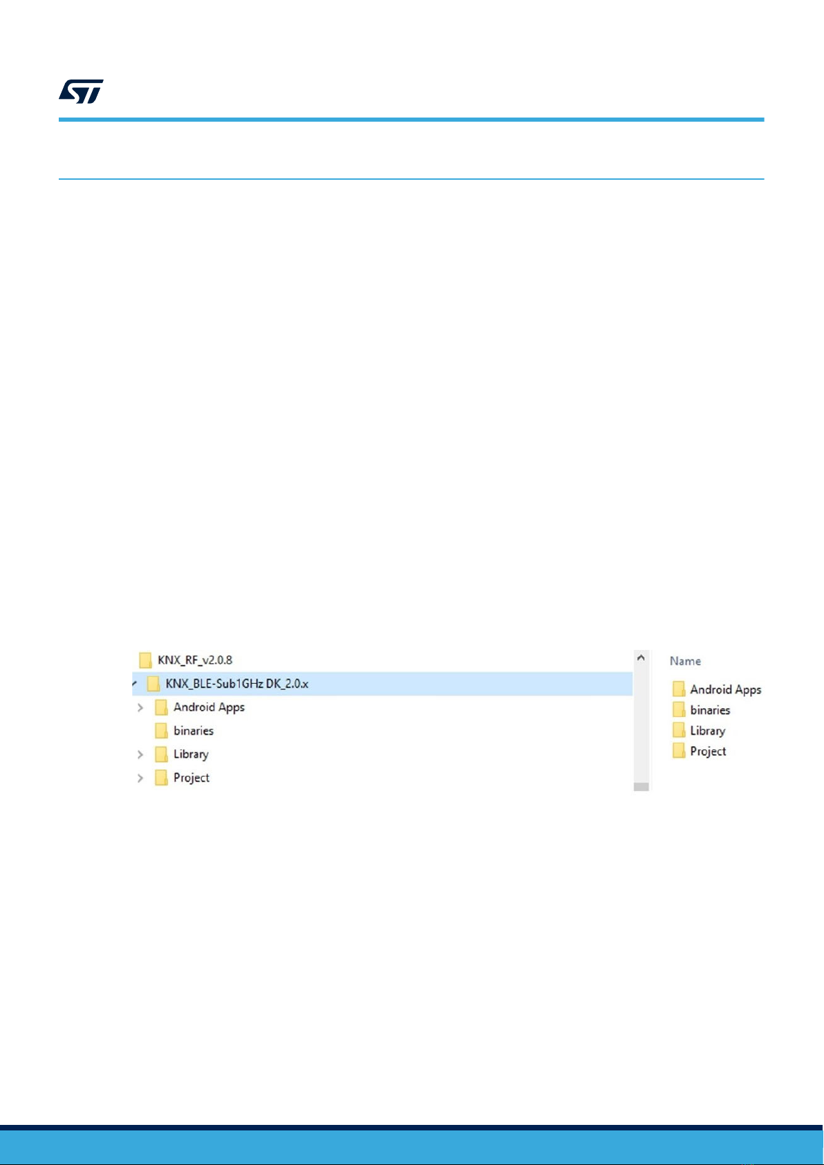
1.2 Folder structure
After downloading the STSW-S2LP-KNX-DK software package, extract its components to a temporary directory.
Figure 1. STSW-S2LP-KNX-DK folder structure
1. Androids Apps (APK file)
2. Pre-compiled binaries
3. Project libraries (BLE, KNX, S2-LP drivers)
4. Keil IDE project examples
1
2
3
4
1.3 Hardware configurations
To run the STSW-S2LP-KNX-DK evaluation package, the following hardware configurations are possible:
• one running on a STEVAL-IDB008V2 evaluation board based on the BlueNRG-2 Bluetooth® LE 5.2 wireless
SoC plus an X-NUCLEO-S2868A1 or X-NUCLEO-S2868A2 expansion board
• one running on a NUCLEO-L073RZ development board plus an X-NUCLEO-S2868A1 or X-NUCLEO-
S2868A2 expansion board
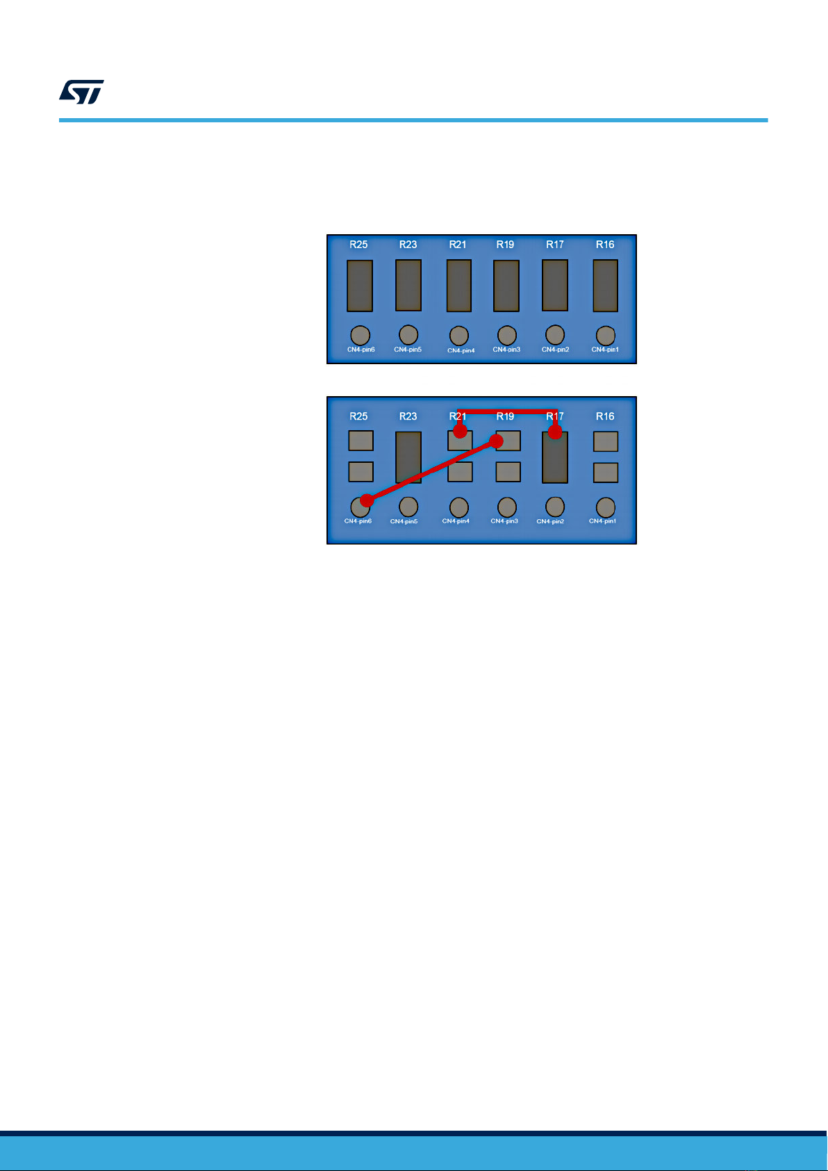
1.3.1 STEVAL-IDB008V2
To run the demo using the BlueNRG-2 Bluetooth® LE 5.2 wireless SoC, you need:
• a STEVAL-IDB008V2 (for further details, refer to UM2071)
UM2920
Getting started
UM2920 - Rev 1 page 2/71

Figure 2. STEVAL-IDB008V2 evaluation board
1.3.1.1 Modifying the STEVAL-IDB008V2
To make the STEVAL-IDB008V2 compatible with the STSW-S2LP-KNX-DK package, perform the below
modifications on the board bottom side.
Step 1. Remove R12.
Step 2. Create a short-circuit between pin 8 and pin 7 on CN3 connector.
Figure 3. CN3 modifications
Before After
Step 3. Remove R25, R21, R19 and R16.
Step 4. Set a short between the internal pad of R21 and R17.
UM2920
Hardware configurations
UM2920 - Rev 1 page 3/71

Step 5. Set a short between pin 6 and CN4 connector and the internal pad of R19.
Figure 4. CN4 modifications
Before
After
Step 6. Remove R11.
Step 7. Create a short-circuit between R8 and DIO8.
1.3.2 NUCLEO-L073RZ
To run the demo using the STM32L073RZ microcontroller, you need:
• a NUCLEO-L073RZ (for further details, refer to UM1727)
UM2920
Hardware configurations
UM2920 - Rev 1 page 4/71

Figure 5. NUCLEO-L073RZ development board
NUCLEO-
L073RZ
1.3.3 X-NUCLEO-S2868A1 and X-NUCLEO-S2868A2
An X-NUCLEO-S2868A2 or X-NUCLEO-S2868A1 expansion board is necessary to provide Sub-1 GHz and
KNX-RF connectivity.
Figure 6. X-NUCLEO-S2868A1 expansion board
UM2920
Hardware configurations
UM2920 - Rev 1 page 5/71

Figure 7. X-NUCLEO-S2868A2 expansion board
1.3.3.1 Modifying X-NUCLEO-S2868A1/X-NUCLEO-S2868A2 expansion boards
To make X-NUCLEO-S2868A1/X-NUCLEO-S2868A2 compatible with the STSW-S2LP-KNX-DK package, when
used with the STEVAL-IDB008V2 only, you have to apply the modifications below to the S2-LP expansion board.
Step 1. Remove R22.
Step 2. Solder R7 to create a short-circuit.
1.4 Software requirements
To use the STSW-S2LP-KNX-DK package, you have to install into your PC/laptop:
• Keil µVision
• KNX ET5
•BlueNRG-X Flasher utility
•STM32CubeProgrammer
• Android apps for BLE connectivity
1.4.1 Keil µVision
Application project examples are provided for Keil project only.
Keil can be used with evaluation license with CM0 and CM0+ up to 256 kB Flash code. It is suitable to evaluate
STEVAL-IDB008V2 (BlueNRG-2 Cortex-M0) or NUCLEO-L073RZ (STM32L073RZ Cortex-M0+).
UM2920
Software requirements
UM2920 - Rev 1 page 6/71

Step 1. Download and install Keil µVision
Figure 8. MDK-ARM download web page
Step 2. Once installation is completed, install MDK5 Software packs to support BlueNRG-2 and
STM32L073RZ
Step 2a. check MDK5 Software Packs (keil.com)
Step 2b. go to Keil section
Step 2c. install the following packages:
◦STMicroelectronics BlueNRG-2 Series Device Support
◦ STMicroelectronics STM32L0 Series Device Support
Figure 9. MDK-ARM device support packs
UM2920
Software requirements
UM2920 - Rev 1 page 7/71

Step 3. Activate the license at https://www2.keil.com/stmicroelectronics-stm32/mdk.
Figure 10. MDK-ARM license activation for Cortex-M0/M0+
Step 3a. Copy PSN code (XXXX-XXXX-XXXX).
Step 3b. Go to Keil IDE license management.
Step 3c. Click on the [Get a LIC via Internet] button.
Step 3d. Fill in the form.
You will receive an e-mail with the new license ID to be entered to activate IDE license.
UM2920
Software requirements
UM2920 - Rev 1 page 8/71

Figure 11. Procedure to activate free Keil license
1.4.2 KNX ETS5
The ETS5 tool, which stands for Engineering Test Software, is needed to install and configure a KNX network
independently from the media used (wired or wireless).
The installation of ETS5 is required to evaluate KNX-RF devices based on BlueNRG-2, S2-LP and STM32L0
solutions.
ETS5 demo license is free and limited to up to 5 KNX devices in the system.
To install ETS5, go to KNX - MyKNX, create an account and download ETS5 Lite demo version.
Figure 12. ETS5 Lite demo download
1.4.3 BlueNRG-X Flasher Utility
To flash and mass erase the BlueNRG BLE SoC chipsets, install the STSW-BNRGFLASHER tool.
UM2920
Software requirements
UM2920 - Rev 1 page 9/71

Figure 13. BlueNRG-X Flasher Utility installation
1.4.4 STM32CubeProgrammer
install STM32CubeProgrammer software
It provides an environment to program STM32 microcontrollers and load pre-compiled binaries.
Figure 14. STM32CubeProgrammer installation
1.5 Dedicated Android apps for BLE connectivity
KNX-RF evaluation package contains the APK file: BlueNRGKNX_Android.apk. It provides dedicated apps for
light control applications using BLE connectivity (to be used with BlueNRG-2 application).
UM2920
Dedicated Android apps for BLE connectivity
UM2920 - Rev 1 page 10/71

Figure 15. Light control app
APK file is available in the /Android Apps folder.
Figure 16. APK file location
1.6 Alternative apps for BLE connectivity
As the APK Android application (working on Galaxy S10 smart phone family) is not maintained, there is an
alternative solution using generic Bluetooth Low Energy apps, such as BLE Scanner, available on Google Store.
UM2920
Alternative apps for BLE connectivity
UM2920 - Rev 1 page 11/71

Figure 17. BLE Scanner app
UM2920
Alternative apps for BLE connectivity
UM2920 - Rev 1 page 12/71

2KNX-RF evaluation package options
2.1 Package overview
KNX-RF package demonstrates:
•S2-LP Sub-1GHz transceiver capabilities to support KNX-RF multi-protocol
•BlueNRG-2 BLE 5.1 system-on-chip capabilities to host KNX-RF stack and to run BLE and KNX-RF stack
with a single Cortex-M0 core (in combination with S2-LP)
•STM32L0 microcontroller capabilities to host KNX-RF stack (in combination with S2-LP)
The evaluation package provides software example projects (based on Keil IDE) to simulate:
• KNX-RF switch application using BlueNRG-2 BLE 5.1 SoC. The application can be controlled by
smartphone
• KNX-RF light application (using VCOM)
Different KNX-RF topologies can be addressed using the evaluation package:
• Standalone mode: point-to-point KNX-RF multi-communication
• KNX ETS5 PC application:
– using Tapko Technologies TP/RF gateway (commercial devices)
– using Tapko Technologies USB dongle (evaluation device)
2.2 KNX-RF frameworks based on BlueNRG-2 BLE 5.1 system-on-chip
KNX-RF evaluation package features a framework based on BlueNRG-2 BLE SoC. It provides a KNX-RF switch
application example using BLE connectivity to control applications.
KNX-RF light application is simulated with another board receiving light control commands (on/off, dimming and
color control).
Each KNX-RF application involves a BlueNRG-2 kit (STEVAL-IDB008V2 with modifications) and an S2-LP
expansion board (X-NUCLEO-S2868A2 or X-NUCLEO-S2868A1 with modifications).
Figure 18. KNX-RF framework based on BlueNRG-2
UM2920
KNX-RF evaluation package options
UM2920 - Rev 1 page 13/71

2.3 KNX-RF frameworks based on STM32L0 microcontroller
Another framework is based on STM32L0 Cortex-M0+ microcontroller. It provides a simple KNX-RF switch
application (VCOM required to simulate buttons) and KNX-RF light application is simulated with another board
receiving light control commands (on/off, dimming and color control).
Each KNX-RF application involves an STM32L0 development board (NUCLEO-L073RZ) and an S2-LP expansion
board (X-NUCLEO-S2868A2 or X-NUCLEO-S2868A1 with modifications).
Figure 19. KNX-RF framework based on STM32L0 microcontroller
2.4 KNX-RF point-to-point topology based on BlueNRG-2 evaluation kits
This point-to-point topology demonstrates KNX-RF multi-communication without KNX infrastructure (based on
wired KNX devices).
It also demonstrates extra connectivity via smartphone (only the KNX-RF switch application is controlled via BLE).
Figure 20. Point-to-point topology based on BlueNRG-2 evaluation kits (STEVAL-IDB008V2)
2.5 KNX-RF point-to-point topology based on STM32L0 development boards
This point-to-point topology demonstrates KNX-RF multi-communication without KNX infrastructure (based on
wired KNX devices).
It is designed for STM32 general purpose microcontrollers belonging to STM32L0 family.
UM2920
KNX-RF frameworks based on STM32L0 microcontroller
UM2920 - Rev 1 page 14/71

Figure 21. Point-to-point topology based on STM32L0 development boards (NUCLEO-L073RZ)
2.6 ETS connectivity through KNX RF/TP gateway based on BlueNRG-2 evaluation
kits
This ETS connectivity topology is based on KNX RF/TP gateway and KNX wired infrastructure (KNX bus power
supply and KNX USB interface). KNX-RF application examples are based on the BlueNRG-2 BLE SoC kits
(STEVAL-IDB008V2). Its purpose is to configure, monitor and control KNX-RF devices using ETS5 tool.
Figure 22. ETS connectivity based on BlueNRG-2 evaluation kits
2.7 ETS connectivity through KNX RF/TP gateway based on STM32L0 development
boards
This ETS connectivity topology is based on KNX RF/TP gateway and KNX wired infrastructure (KNX bus power
supply and KNX USB interface). KNX-RF application examples are based on the STM32L0 development boards
(NUCLEO-L073RZ). Its purpose is to configure, monitor and control KNX-RF devices using ETS5 tool.
Moreover, it demonstrates KNX-RF communication with KNX infrastructure (based on wired KNX devices).
UM2920
ETS connectivity through KNX RF/TP gateway based on BlueNRG-2 evaluation kits
UM2920 - Rev 1 page 15/71

Figure 23. ETS connectivity based on STM32L0 development boards
2.8 ETS connectivity through USB dongle based on BlueNRG-2 evaluation kits
This topology is based on Tapko Technology USB dongle and KNX wired infrastructure (KNX bus power supply
and KNX USB interface). KNX-RF application examples are based on BlueNRG-2 BLE SoC kits (STEVAL-
IDB008V2). Its purpose is to configure, monitor and control KNX-RF devices using ETS5 tool.
Moreover, it demonstrates KNX-RF communication with KNX infrastructure (based on wired KNX devices) as well
as extra connectivity through smartphone (only the KNX-RF switch application is controlled via BLE).
Figure 24. ETS connectivity through USB dongle based on BlueNRG-2 evaluation kits
UM2920
ETS connectivity through USB dongle based on BlueNRG-2 evaluation kits
UM2920 - Rev 1 page 16/71

2.9 ETS connectivity through USB dongle based on STM32L0 development boards
This topology is based on Tapko Technology USB dongle and KNX wired infrastructure (KNX bus power supply
and KNX USB interface). KNX-RF application examples are based on STM32L0 development boards (NUCLEO-
L073RZ). Its purpose is to configure, monitor and control KNX-RF devices using ETS5 tool.
Moreover, it demonstrates KNX-RF communication with KNX infrastructure (based on wired KNX devices).
Figure 25. ETS connectivity through USB dongle based on STM32L0 development boards
UM2920
ETS connectivity through USB dongle based on STM32L0 development boards
UM2920 - Rev 1 page 17/71

3Point-to-point KNX-RF communication setup
This section describes KNX-RF point-to-point communication setup either using BlueNRG-2 kits or using
STM32L0 kits.
3.1 BlueNRG-2 setup
3.1.1 Hardware setup
Step 1. For BlueNRG-2 kit evaluation setup, use two pairs of:
–BlueNRG-2 kits: STEVAL-IDB008V2 (with hardware modifications)
–S2-LP kits: X-NUCLEO-S2868A2 or X-NUCLEO-S2868A1 (with hardware modifications)
Step 2. Plug S2-LP and BlueNRG-2 kits as shown below.
Figure 26. S2-LP and BlueNRG-2 stack plus antennas
3.1.2 Software setup
Step 1. Launch STSW-BNRGFLASHER.
Note: Before flashing pre-compiled binaries, it is recommended to erase BlueNRG-2 Flash memory.
UM2920
Point-to-point KNX-RF communication setup
UM2920 - Rev 1 page 18/71

Step 2. Connect STEVAL-IDB008V2 to your PC/laptop by selecting the associated COM port in the tool.
Figure 27. Selecting the COM port
Step 3. Mass erase the two BlueNRG-2 kits.
Figure 28. Mass erase
Step 4. Download the following files on the boards:
–BlueNRG2_RGB_Actuator.hex
– BlueNRG2_RGB_PushButton.hex
Figure 29. Hex files
UM2920
BlueNRG-2 setup
UM2920 - Rev 1 page 19/71

Step 5. Follow the procedure described below using STSW-BNRGFLASHER.
Figure 30. STSW-BNRGFLASHER procedure
Step 6. Use the binaries according to the topology shown below.
Figure 31. Topology for hex files
Step 7. For the LED actuator application and to get lighting control commands, set up Tera Term (or
hyperterminal) as shown below.
Figure 32. Tera Term setup
Select COM port Configure serial port
Choose 115 kbaud
UM2920
BlueNRG-2 setup
UM2920 - Rev 1 page 20/71
Table of contents
Other ST Motherboard manuals

ST
ST VM6101 User manual

ST
ST STEVAL-PLC001V1 User manual

ST
ST STM3210E-EVAL User manual

ST
ST SPC560B-DIS User manual

ST
ST STM32H743I-EVAL User manual

ST
ST STEVAL-PCC010V1 User manual

ST
ST STEVAL-IHM015V1 User manual

ST
ST STEVAL-ISB041V1 User manual

ST
ST STEVAL-BLUEPLUG1 User manual

ST
ST SPC572L-DISP User manual

ST
ST STM32MP157D-EV1 User manual

ST
ST STR730-EVAL User manual

ST
ST STM3241G-EVAL User manual

ST
ST Teseo-VIC3DA User manual

ST
ST STM32100B-EVAL User manual

ST
ST STEVAL-ISC004V1 User manual

ST
ST SPC563M64CAL144 User manual

ST
ST STR910-EVAL User manual

ST
ST STM32L152-EVAL User manual

ST
ST X-NUCLEO-S2868A1 User manual